1994 JEEP CHEROKEE brake light
[x] Cancel search: brake lightPage 156 of 1784

Brake drag also has a direct effect on fuel economy.
If undetected, minor brake drag can be misdiagnosed
as an engine or transmission/torque converter prob-
lem.
Minor drag will usually cause slight surface char-
ring of the lining. It can also generate hard spots in
rotors and drums from the overheat/cool down pro-
cess. In most cases, the rotors, drums, wheels and
tires are quite warm to the touch after the vehicle is
stopped.
Severe drag can char the brake lining all the way
through. It can also distort and score rotors and
drums to the point of replacement. The wheels, tires
and brake components will be extremely hot. In se-
vere cases, the lining may generate smoke as it chars
from overheating.
An additional cause of drag involves the use of in-
correct length caliper mounting bolts. Bolts that are
too long can cause a partial apply condition. The cor-
rect caliper bolts have a shank length of 67 mm
(2.637 in.), plus or minus 0.6 mm (0.0236 in.). Refer
to the Disc Brake service section for more detail on
caliper bolt dimensions and identification.
Some common causes of brake drag are:
²loose or damaged wheel bearing
²seized or sticking caliper or wheel cylinder piston
²caliper binding on bushings or slide surfaces
²wrong length caliper mounting bolts (too long)
²loose caliper mounting bracket
²distorted brake drum or shoes
²rear brakeshoes binding on worn/damaged support
plates
²severely rusted/corroded components
²misassembled components.
If brake drag occurs at all wheels, the problem may
be related to a blocked master cylinder compensator
port or faulty power booster (binds-does not release).
The brakelight switch can also be a cause of drag.
An improperly mounted or adjusted brakelight
switch can prevent full brake pedal return. The re-
sult will be the same as if the master cylinder com-
pensator ports are blocked. The brakes would be
partially applied causing drag.
BRAKE FADE
Brake fade is a product of overheating caused by
brake drag. However, overheating and subsequent
fade can also be caused by riding the brake pedal,
making repeated high deceleration stops in a short
time span, or constant braking on steep roads. Refer
to the Brake Drag information in this section for
causes.
PEDAL PULSATION
Pedal pulsation is caused by components that are
loose, or beyond tolerance limits.
Disc brake rotors with excessive lateral runout or
thickness variation, or out of round brake drums arethe primary causes of pulsation. Other causes are
loose wheel bearings or calipers and worn, damaged
tires.
PULL
A front pull condition could be the result of:
²contaminated lining in one caliper
²seized caliper piston
²binding caliper
²wrong caliper mounting bolts (too long)
²loose caliper
²loose or corroded mounting bolts
²improper brakeshoes
²damaged rotor
²incorrect wheel bearing adjustment (at one wheel)
A worn, damaged wheel bearing or suspension
component are further causes of pull. A damaged
front tire (bruised, ply separation) can also cause
pull. Wrong caliper bolts (too long) will cause a par-
tial apply condition and pull if only one caliper is in-
volved.
A common and frequently misdiagnosed pull condi-
tion is where direction of pull changes after a few
stops. The cause is a combination of brake drag fol-
lowed by fade at the dragging brake unit.
As the dragging brake overheats, efficiency is so
reduced that fade occurs. If the opposite brake unit is
still functioning normally, its braking effect is mag-
nified. This causes pull to switch direction in favor of
the brake unit that is functioning normally.
When diagnosing a change in pull condition, re-
member that pull will return to the original direction
if the dragging brake unit is allowed to cool down
(and is not seriously damaged).
REAR BRAKE GRAB
Rear grab (or pull) is usually caused by contami-
nated lining, bent or binding shoes and support
plates, or improperly assembled components. This is
particularly true when only one rear wheel is in-
volved. However, when both rear wheels are affected,
the master cylinder or proportioning valve could be
at fault.
BRAKES DO NOT HOLD AFTER DRIVING
THROUGH DEEP WATER PUDDLES
This condition is generally caused by water soaked
lining. If the lining is only wet, it can be dried by
driving with the brakes lightly applied for a mile or
two. However, if the lining is both wet and dirty, dis-
assembly and cleaning will be necessary.
BRAKE FLUID CONTAMINATION
There are two basic causes of brake fluid contami-
nation. The first involves allowing dirt, debris, or
other liquid materials to enter the cylinder reservoirs
JBRAKES 5 - 9
Page 158 of 1784
assembled, they will not function. In addition, since
the adjuster mechanism only works during reverse
stops, it is important that complete stops be made.
The adjuster mechanism does not operate when roll-
ing stops are made in reverse. The vehicle must be
brought to a complete halt before the adjuster lever
will turn the adjuster screw.
A condition where the parking brakes do not hold,
will most probably be due to a wheel brake compo-
nent.
Items to look for when diagnosing a parking brake
problem, are:
²rear brakeshoe wear
²rear brakedrum wear
²brakedrums machined beyond allowable diameter
(oversize)
²parking brake front cable not secured to lever
²parking brake rear cable seized
²parking brake strut reversed
²parking brake strut not seated in both shoes
²parking brake lever not seated in secondary shoe
²parking brake lever or brakeshoe bind on support
plate
²brakeshoes reversed
²adjuster screws seized
²adjuster screws reversed
²holddown or return springs misassembled or lack
tension
²wheel cylinder pistons seized
Brake drums that are machined oversize are diffi-
cult to identify. If oversize drums are suspected, the
diameter of the braking surface will have to be
checked with an accurate drum gauge. Oversize
drums will cause low brake pedal and lack of park-
ing brake holding ability.
Improper parking brake strut and lever installa-
tion will result in unsatisfactory parking brake oper-
ation. Intermixing the adjuster screws will cause
drag, bind and pull along with poor parking brake
operation.
Parking brake adjustment and parts replacement
procedures are described in the Parking Brake sec-
tion.
MASTER CYLINDER/POWER BOOSTER TEST
(1) Start engine and check booster vacuum hose
connections. Hissing noise indicates vacuum leak.
Correct any vacuum leak before proceeding.
(2) Stop engine and shift transmission into Neu-
tral.
(3) Pump brake pedal until all vacuum reserve in
booster is depleted.
(4) Press and hold brake pedal under light foot
pressure.
(a) If pedal holds firm, proceed to step (5).
(b) If pedal does not hold firm and falls away,
master cylinder is faulty (internal leakage). Over-
haul or replace cylinder.(5) Start engine and note pedal action.
(a) If pedal falls away slightly under light foot
pressure then holds firm, proceed to step (6).
(b) If no pedal action is discernible, power
booster or vacuum check valve is faulty. Install
known good check valve and repeat steps (2)
through (5).
(6) Rebuild booster vacuum reserve as follows: Re-
lease brake pedal. Increase engine speed to 1500
rpm, close throttle and immediately turn off ignition.
(7) Wait a minimum of 90 seconds and try brake
action again. Booster should provide two or more
vacuum assisted pedal applications. If vacuum assist
is not provided, perform booster and check valve vac-
uum tests.
POWER BOOSTER CHECK VALVE TEST
(1) Disconnect vacuum hose from check valve.
(2) Remove check valve and valve seal from
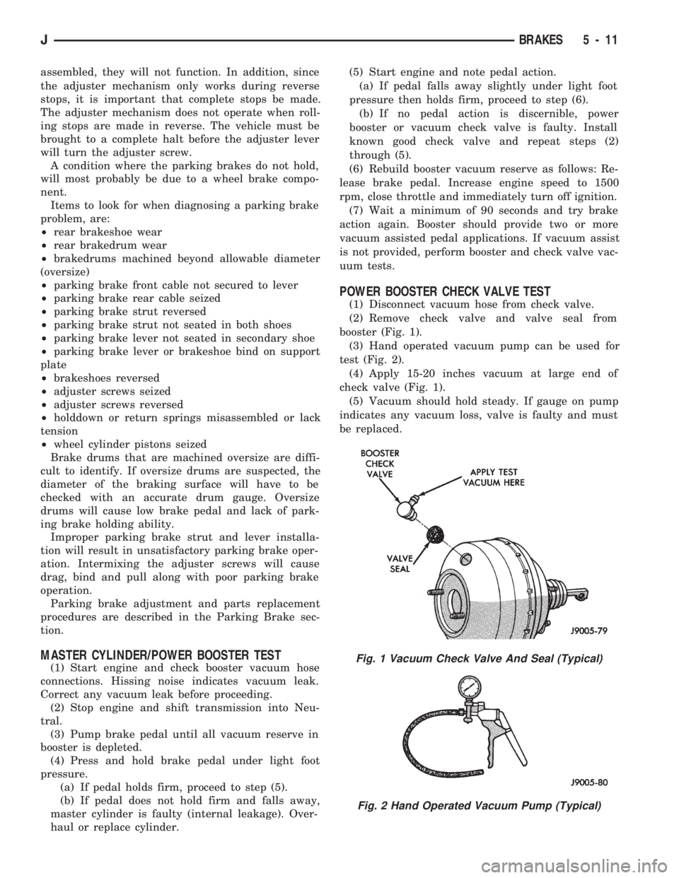
booster (Fig. 1).
(3) Hand operated vacuum pump can be used for
test (Fig. 2).
(4) Apply 15-20 inches vacuum at large end of
check valve (Fig. 1).
(5) Vacuum should hold steady. If gauge on pump
indicates any vacuum loss, valve is faulty and must
be replaced.
Fig. 1 Vacuum Check Valve And Seal (Typical)
Fig. 2 Hand Operated Vacuum Pump (Typical)
JBRAKES 5 - 11
Page 161 of 1784
CAUTION: Do not allow the master cylinder to run
out of fluid when bleeding the brakes. An empty
cylinder will allow additional air to be drawn into
the system. Check the cylinder fluid level frequently
and add fluid as needed.
(10) Bleed each wheel brake unit as follows:
(a) Open caliper or wheel cylinder bleed fitting
1/2 to 3/4 turn.
(b) Have helper press and hold brake pedal to
floor.Do not pump brake pedal while bleeding.
Air in system will be compressed into small
bubbles that are distributed throughout hy-
draulic system. This will make a second and
third bleeding operation necessary.
(c) Tighten bleed fitting and have helper release
brake pedal. Continue bleeding operation until
fluid entering bleed container is clear and free of
bubbles.
(d) Repeat bleeding operation at remaining
wheel brake units.
(e) Discard fluid bled into glass container. It
should not be reused.
(11) Check and adjust master cylinder fluid level.
(12) Verify proper brake operation before moving
vehicle.
PRESSURE BLEEDING
The front brake metering valve is located in the
forward end of the combination valve. The valve
stem is accessible from the same end of the valve.
The stem must be either pressed inward, or held out-
ward slightly in order to bleed the front brakes.
(1) Fill bleeder tank if necessary.
(2) Purge air from bleeder tank and lines before
proceeding.(3) Wipe master cylinder cover clean.
(4) Remove master cylinder cover and install pres-
sure hose adapter in place of cover. A suitable
adapter will usually be available from tank manufac-
turer.
(5) Connect bleeder tank pressure hose to adapter.
(6) Bleed master cylinder first. Then bleed rear
brakes as described in manual bleeding procedure.
(7) Bleed front brakes as described in manual
bleeding procedure. Have helper hold metering valve
open by pressing valve stem inward slightly. Amount
of valve stem movement needed to hold valve open is
quite modest. Do not use excessive force.
(8) Remove pressure bleeding equipment and top
off master cylinder reservoir.
BRAKE BLEEDINGÐXJ/YJ WITH ABS BRAKES
A different bleeding method is required for the
ABS system. It is basically a three step process
consisting of: A conventional manual brake
bleed. A second bleed using the DRB II, fol-
lowed by a repeat of the conventional manual
bleed procedure. Recommended ABS bleeding
procedure is as follows:
(1) Clean master cylinder reservoir caps and reser-
voir exterior. Dirt, foreign material on the caps and
reservoir must not be allowed to enter reservoir.
(2) Fill reservoir with Mopar brake fluid, or equiv-
alent quality fluid meeting SAE 1703 and DOT 3
standards.
(3) Recommended bleeding sequence is:
²master cylinder
²HCU valve body (at fluid lines)
²right rear wheel
²left rear wheel
²right front wheel
²left front wheel.
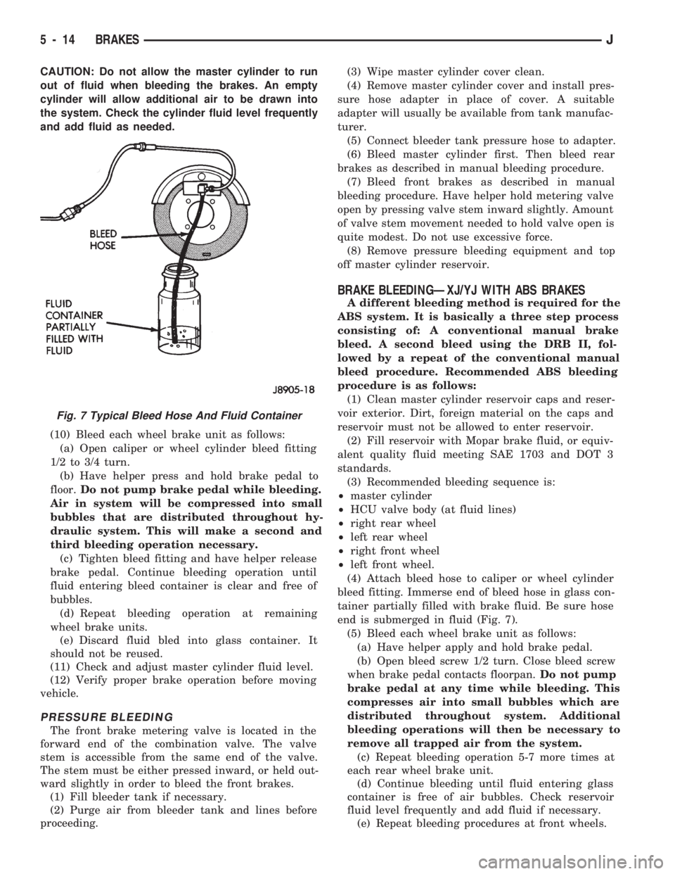
(4) Attach bleed hose to caliper or wheel cylinder
bleed fitting. Immerse end of bleed hose in glass con-
tainer partially filled with brake fluid. Be sure hose
end is submerged in fluid (Fig. 7).
(5) Bleed each wheel brake unit as follows:
(a) Have helper apply and hold brake pedal.
(b) Open bleed screw 1/2 turn. Close bleed screw
when brake pedal contacts floorpan.Do not pump
brake pedal at any time while bleeding. This
compresses air into small bubbles which are
distributed throughout system. Additional
bleeding operations will then be necessary to
remove all trapped air from the system.
(c) Repeat bleeding operation 5-7 more times at
each rear wheel brake unit.
(d) Continue bleeding until fluid entering glass
container is free of air bubbles. Check reservoir
fluid level frequently and add fluid if necessary.
(e) Repeat bleeding procedures at front wheels.
Fig. 7 Typical Bleed Hose And Fluid Container
5 - 14 BRAKESJ
Page 167 of 1784
STANDARD MASTER CYLINDER
INDEX
page page
General Service Information................ 20
Master Cylinder Installation................. 20Master Cylinder Overhaul.................. 20
Master Cylinder Removal.................. 20
GENERAL SERVICE INFORMATION
The service information in this section covers the
standard (non-ABS) master cylinder only. The center
feed master cylinder used with the ABS system is
covered in the antilock brake component service sec-
tion.
MASTER CYLINDER REMOVAL
(1) Disconnect brake lines at master cylinder.
(2) Remove cylinder mounting nuts and remove
master cylinder.
(3) Remove cylinder cover and drain fluid.
MASTER CYLINDER INSTALLATION
(1) Bleed master cylinder on bench before installa-
tion. Refer to overhaul assembly procedure in this
section for bleeding method.
(2) Install cylinder on brake booster studs and in-
stall cylinder attaching nuts. Tighten nuts to 21 NIm
(15 ft. lbs.).
(3) Connect brakelines to cylinder.
(4) Fill and bleed brake system.
MASTER CYLINDER OVERHAUL
CYLINDER DISASSEMBLY
(1) Remove cylinder cover and drain fluid.
(2) Examine cylinder cover seal. Discard seal if
torn or distorted.
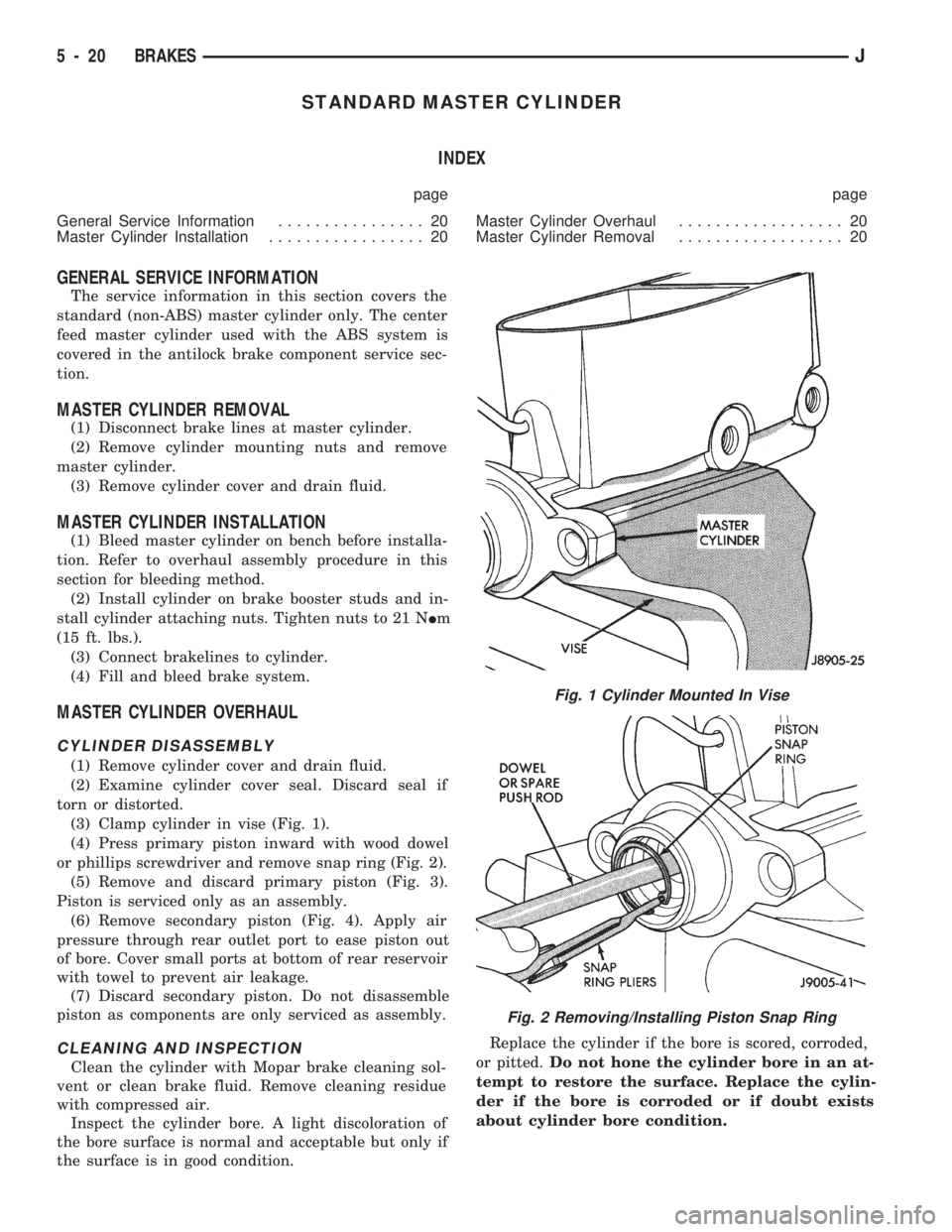
(3) Clamp cylinder in vise (Fig. 1).
(4) Press primary piston inward with wood dowel
or phillips screwdriver and remove snap ring (Fig. 2).
(5) Remove and discard primary piston (Fig. 3).
Piston is serviced only as an assembly.
(6) Remove secondary piston (Fig. 4). Apply air
pressure through rear outlet port to ease piston out
of bore. Cover small ports at bottom of rear reservoir
with towel to prevent air leakage.
(7) Discard secondary piston. Do not disassemble
piston as components are only serviced as assembly.
CLEANING AND INSPECTION
Clean the cylinder with Mopar brake cleaning sol-
vent or clean brake fluid. Remove cleaning residue
with compressed air.
Inspect the cylinder bore. A light discoloration of
the bore surface is normal and acceptable but only if
the surface is in good condition.Replace the cylinder if the bore is scored, corroded,
or pitted.Do not hone the cylinder bore in an at-
tempt to restore the surface. Replace the cylin-
der if the bore is corroded or if doubt exists
about cylinder bore condition.
Fig. 1 Cylinder Mounted In Vise
Fig. 2 Removing/Installing Piston Snap Ring
5 - 20 BRAKESJ
Page 171 of 1784
DISC BRAKES
INDEX
page page
Caliper Assembly........................ 29
Caliper Cleaning and Inspection............. 28
Caliper Disassembly...................... 27
Caliper Installation........................ 30
Caliper Operation and Wear Compensation..... 24
Caliper Removal......................... 27
Disc Brake Rotor Refinishing................ 32
Disc Brake Rotor Runout................... 31Disc Brake Rotor Thickness................ 31
Disc Brake Rotor Thickness Variation......... 31
Disc Brakeshoe Installation................. 26
Disc Brakeshoe Removal.................. 25
General Information....................... 24
Rotor Installation......................... 30
Rotor Removal.......................... 30
Wheel Nut Tightening..................... 32
GENERAL INFORMATION
1994 Jeep XJ/YJ models are equipped with single
piston, floating-type disc brake calipers. Ventilated,
cast rotors are used for all applications.
The disc brake calipers are supported in mounting
arms that are an integral part of the steering
knuckle. The calipers slide on mounting bolts that
also attach the calipers to the steering knuckle.
CALIPER OPERATION AND WEAR COMPENSATION
Caliper Operation
The significant feature of single piston caliper op-
eration is that the calipers are free to slide laterally
on the mounting bolts. It is the freedom of lateral
movement that allows continous compensation for
lining wear.
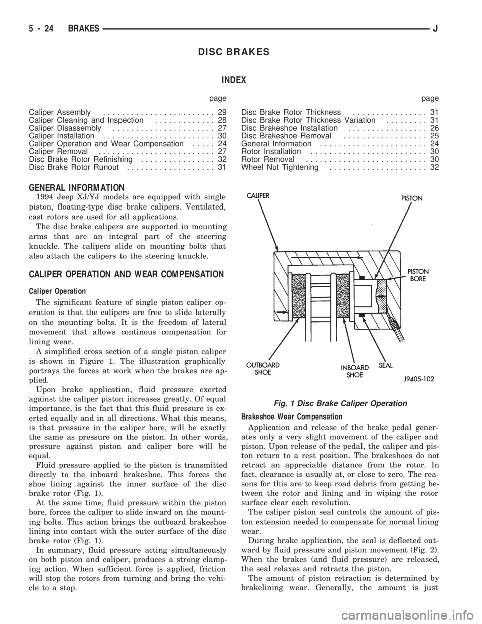
A simplified cross section of a single piston caliper
is shown in Figure 1. The illustration graphically
portrays the forces at work when the brakes are ap-
plied.
Upon brake application, fluid pressure exerted
against the caliper piston increases greatly. Of equal
importance, is the fact that this fluid pressure is ex-
erted equally and in all directions. What this means,
is that pressure in the caliper bore, will be exactly
the same as pressure on the piston. In other words,
pressure against piston and caliper bore will be
equal.
Fluid pressure applied to the piston is transmitted
directly to the inboard brakeshoe. This forces the
shoe lining against the inner surface of the disc
brake rotor (Fig. 1).
At the same time, fluid pressure within the piston
bore, forces the caliper to slide inward on the mount-
ing bolts. This action brings the outboard brakeshoe
lining into contact with the outer surface of the disc
brake rotor (Fig. 1).
In summary, fluid pressure acting simultaneously
on both piston and caliper, produces a strong clamp-
ing action. When sufficient force is applied, friction
will stop the rotors from turning and bring the vehi-
cle to a stop.Brakeshoe Wear Compensation
Application and release of the brake pedal gener-
ates only a very slight movement of the caliper and
piston. Upon release of the pedal, the caliper and pis-
ton return to a rest position. The brakeshoes do not
retract an appreciable distance from the rotor. In
fact, clearance is usually at, or close to zero. The rea-
sons for this are to keep road debris from getting be-
tween the rotor and lining and in wiping the rotor
surface clear each revolution.
The caliper piston seal controls the amount of pis-
ton extension needed to compensate for normal lining
wear.
During brake application, the seal is deflected out-
ward by fluid pressure and piston movement (Fig. 2).
When the brakes (and fluid pressure) are released,
the seal relaxes and retracts the piston.
The amount of piston retraction is determined by
brakelining wear. Generally, the amount is just
Fig. 1 Disc Brake Caliper Operation
5 - 24 BRAKESJ
Page 173 of 1784
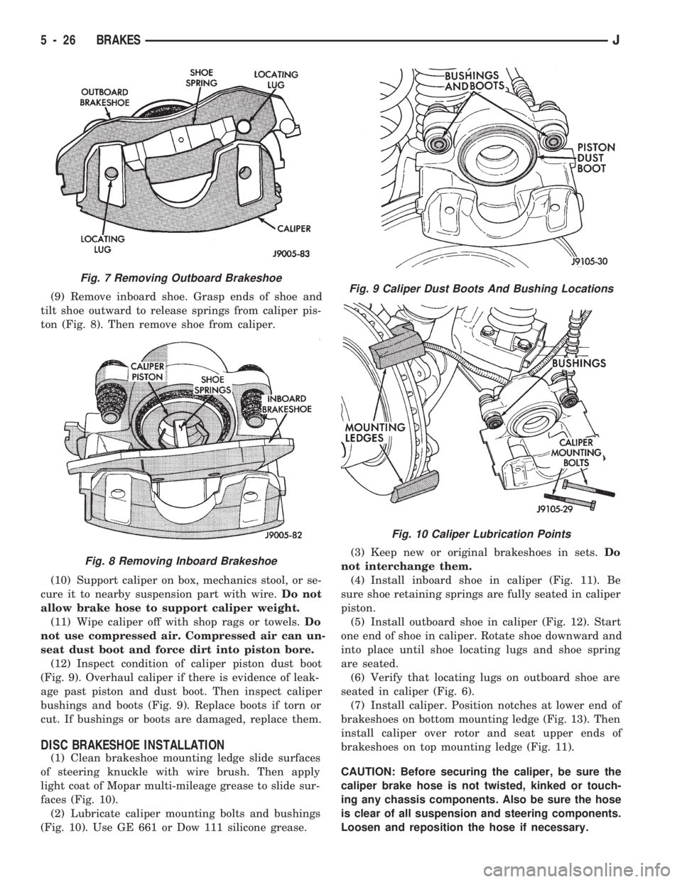
(9) Remove inboard shoe. Grasp ends of shoe and
tilt shoe outward to release springs from caliper pis-
ton (Fig. 8). Then remove shoe from caliper.
(10) Support caliper on box, mechanics stool, or se-
cure it to nearby suspension part with wire.Do not
allow brake hose to support caliper weight.
(11) Wipe caliper off with shop rags or towels.Do
not use compressed air. Compressed air can un-
seat dust boot and force dirt into piston bore.
(12) Inspect condition of caliper piston dust boot
(Fig. 9). Overhaul caliper if there is evidence of leak-
age past piston and dust boot. Then inspect caliper
bushings and boots (Fig. 9). Replace boots if torn or
cut. If bushings or boots are damaged, replace them.
DISC BRAKESHOE INSTALLATION
(1) Clean brakeshoe mounting ledge slide surfaces
of steering knuckle with wire brush. Then apply
light coat of Mopar multi-mileage grease to slide sur-
faces (Fig. 10).
(2) Lubricate caliper mounting bolts and bushings
(Fig. 10). Use GE 661 or Dow 111 silicone grease.(3) Keep new or original brakeshoes in sets.Do
not interchange them.
(4) Install inboard shoe in caliper (Fig. 11). Be
sure shoe retaining springs are fully seated in caliper
piston.
(5) Install outboard shoe in caliper (Fig. 12). Start
one end of shoe in caliper. Rotate shoe downward and
into place until shoe locating lugs and shoe spring
are seated.
(6) Verify that locating lugs on outboard shoe are
seated in caliper (Fig. 6).
(7) Install caliper. Position notches at lower end of
brakeshoes on bottom mounting ledge (Fig. 13). Then
install caliper over rotor and seat upper ends of
brakeshoes on top mounting ledge (Fig. 11).
CAUTION: Before securing the caliper, be sure the
caliper brake hose is not twisted, kinked or touch-
ing any chassis components. Also be sure the hose
is clear of all suspension and steering components.
Loosen and reposition the hose if necessary.
Fig. 7 Removing Outboard Brakeshoe
Fig. 8 Removing Inboard Brakeshoe
Fig. 9 Caliper Dust Boots And Bushing Locations
Fig. 10 Caliper Lubrication Points
5 - 26 BRAKESJ
Page 176 of 1784

Do not hone the caliper piston bore. Replace the cal-
iper if the bore exhibits any of the aforementioned
conditions.
Inspect the caliper piston. The piston is made from
a phenolic resin (plastic material) and should be
smooth and clean. Replace the piston if cracked,
chipped, or scored. Do not attempt to restore a
scored, or corroded piston surface by sanding or pol-
ishing. The piston must be replaced if damaged.
CAUTION: Never interchange phenolic resin and
steel caliper pistons. The seals, seal grooves, cali-
per bores and piston tolerances are different for
resin and steel pistons. Do not intermix these com-
ponents.
Inspect the caliper mounting bolt bushings and
boots. Replace the boots if cut or torn. Clean and lu-
bricate the bushings with GE 661 or Dow 111 sili-
cone grease if necessary.
Inspect condition of the caliper mounting bolts. Re-
place the bolts if corroded, rusted, or worn. Do not re-
use the bolts if unsure of their condition.
Length of the caliper mounting bolts is also ex-
tremely important.
Use the replacement bolts specified in the parts
catalog at all times. Do not use substitute bolts.
Bolts that are too long will partially apply the in-
board brakeshoe causing drag and pull. Refer to the
caliper and brakeshoe installation procedures for ser-
vice details and bolt dimensions.
CALIPER ASSEMBLY
(1) Coat caliper piston bore, new piston seal and
piston with clean, fresh brake fluid.
(2) Lubricate caliper bushings and interior of bush-
ing boots with GE 661, Dow 111, or Permatex Dielec-
tric silicone grease.
(3) Install bushing boots in caliper first. Then in-
sert bushing into boot and push bushing into place
(Fig. 20).(4) Install new piston seal in caliper bore. Press
seal into seal groove with finger (Fig. 21).
(5) Install dust boot on caliper piston (Fig. 22).
Slide boot over piston and seat boot in piston groove.
(6) Start caliper piston in bore by hand (Fig. 23).
Use a turn and push motion to work piston into seal.
Once piston is started in seal, press pistononly part
wayinto bore.
(7) Apply light coat of GE 661, Dow 111, or Per-
matex silicone grease to indicated areas (circumfer-
Fig. 20 Installing Bushings And Boots
Fig. 21 Installing Piston Seal
Fig. 22 Installing Dust Boot On Piston
Fig. 23 Installing Caliper Piston
JBRAKES 5 - 29
Page 177 of 1784
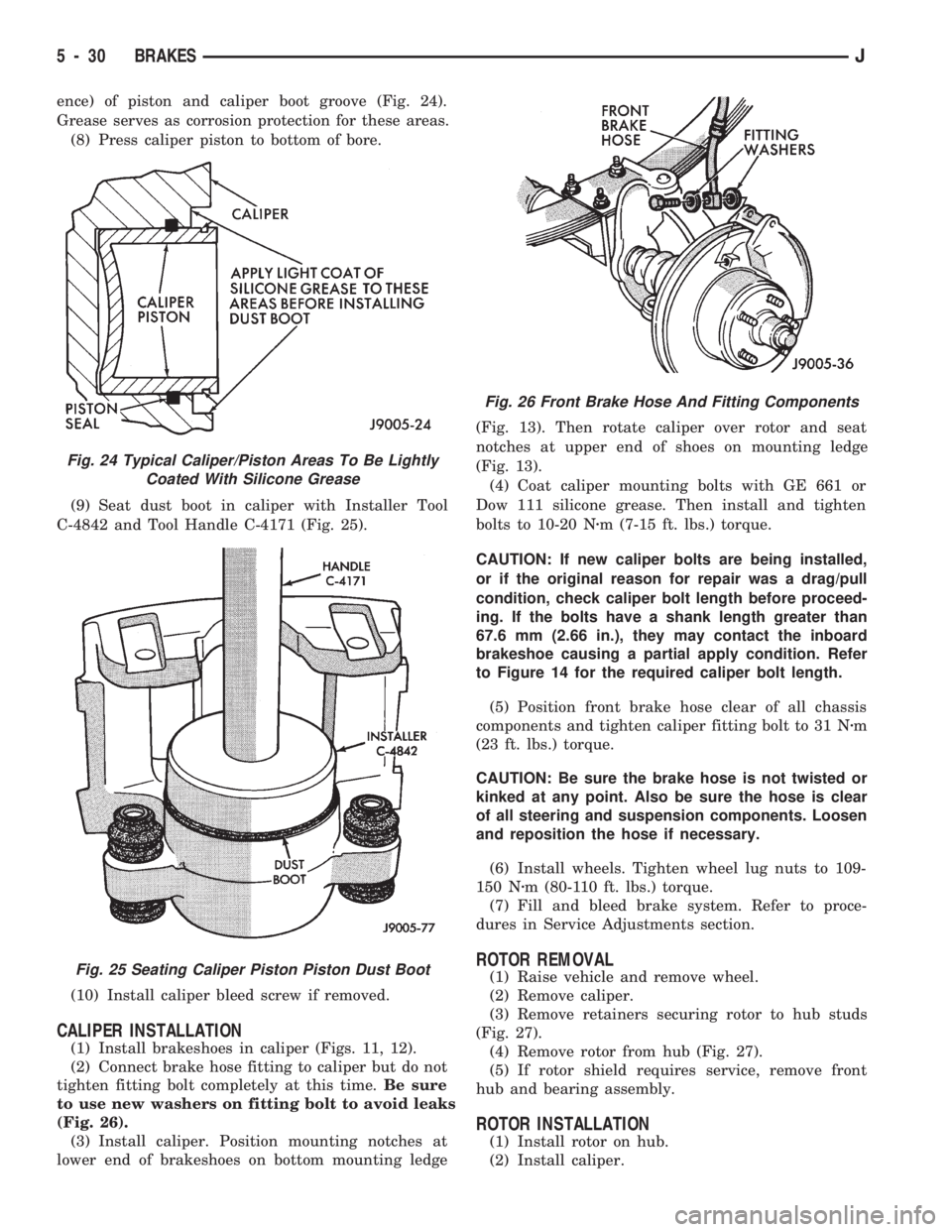
ence) of piston and caliper boot groove (Fig. 24).
Grease serves as corrosion protection for these areas.
(8) Press caliper piston to bottom of bore.
(9) Seat dust boot in caliper with Installer Tool
C-4842 and Tool Handle C-4171 (Fig. 25).
(10) Install caliper bleed screw if removed.
CALIPER INSTALLATION
(1) Install brakeshoes in caliper (Figs. 11, 12).
(2) Connect brake hose fitting to caliper but do not
tighten fitting bolt completely at this time.Be sure
to use new washers on fitting bolt to avoid leaks
(Fig. 26).
(3) Install caliper. Position mounting notches at
lower end of brakeshoes on bottom mounting ledge(Fig. 13). Then rotate caliper over rotor and seat
notches at upper end of shoes on mounting ledge
(Fig. 13).
(4) Coat caliper mounting bolts with GE 661 or
Dow 111 silicone grease. Then install and tighten
bolts to 10-20 Nzm (7-15 ft. lbs.) torque.
CAUTION: If new caliper bolts are being installed,
or if the original reason for repair was a drag/pull
condition, check caliper bolt length before proceed-
ing. If the bolts have a shank length greater than
67.6 mm (2.66 in.), they may contact the inboard
brakeshoe causing a partial apply condition. Refer
to Figure 14 for the required caliper bolt length.
(5) Position front brake hose clear of all chassis
components and tighten caliper fitting bolt to 31 Nzm
(23 ft. lbs.) torque.
CAUTION: Be sure the brake hose is not twisted or
kinked at any point. Also be sure the hose is clear
of all steering and suspension components. Loosen
and reposition the hose if necessary.
(6) Install wheels. Tighten wheel lug nuts to 109-
150 Nzm (80-110 ft. lbs.) torque.
(7) Fill and bleed brake system. Refer to proce-
dures in Service Adjustments section.
ROTOR REMOVAL
(1) Raise vehicle and remove wheel.
(2) Remove caliper.
(3) Remove retainers securing rotor to hub studs
(Fig. 27).
(4) Remove rotor from hub (Fig. 27).
(5) If rotor shield requires service, remove front
hub and bearing assembly.
ROTOR INSTALLATION
(1) Install rotor on hub.
(2) Install caliper.
Fig. 24 Typical Caliper/Piston Areas To Be Lightly
Coated With Silicone Grease
Fig. 25 Seating Caliper Piston Piston Dust Boot
Fig. 26 Front Brake Hose And Fitting Components
5 - 30 BRAKESJ