1994 JEEP CHEROKEE brake light
[x] Cancel search: brake lightPage 190 of 1784
ANTILOCK BRAKE SYSTEM OPERATION
INDEX
page page
ABS Operation in Antilock Braking Mode....... 43
ABS Operation in Normal Braking Mode....... 43
Acceleration Switch Operation............... 45
ECY Operation.......................... 46HCU Pump and Pedal Travel Sensor Operation . 44
HCU Solenoid Valve Operation.............. 43
System Power-Up and Initialization........... 43
Wheel Speed Sensor Operation............. 45
SYSTEM POWER-UP AND INITIALIZATION
The antilock system is in standby mode with the
ignition switch in Off or Accessory position. The an-
tilock electrical components are not operational.
Turning the ignition switch to On or Run position
allows battery voltage to flow through the switch to
the ECU ignition terminal.
The ABS system is activated when battery voltage
is supplied to the ECU. The ECU performs a system
initialization procedure at this point. Initialization
consists of a static and dynamic self check of system
electrical components.
The static check occurs immediately after the igni-
tion switch is turned to the On position. The dynamic
check occurs when vehicle road speed reaches ap-
proximately 10 kph (6 mph). During the dynamic
check, the ECU briefly cycles the pump to verify op-
eration. The HCU solenoids are checked continu-
ously.
If an ABS component exhibits a fault during ini-
tialization, the ECU illuminates the amber warning
light and registers a fault code in the microprocessor
memory.
ABS OPERATION IN NORMAL BRAKING MODE
The ECU monitors wheel speed sensor inputs con-
tinuously while the vehicle is in motion. However,
the ECU will not activate any ABS components as
long as sensor inputs and the acceleration switch in-
dicate normal braking.
During normal braking, the master cylinder, power
booster and wheel brake units all function as they
would in a vehicle without ABS. The HCU compo-
nents are not activated.
ABS OPERATION IN ANTILOCK BRAKING MODE
The purpose of the antilock system is to prevent
wheel lockup during periods of high wheel slip. Pre-
venting lockup helps maintain vehicle braking action
and steering control.
The antilock ECU activates the system whenever
sensor signals indicate periods of high wheel slip.
High wheel slip can be described as the point where
wheel rotation begins approaching zero (or lockup)
during braking. Periods of high wheel slip occur
when brake stops involve high pedal pressure and
rate of vehicle deceleration.The antilock system retards lockup during high
slip conditions by modulating fluid apply pressure to
the wheel brake units.
Brake fluid apply pressure is modulated according
to wheel speed, degree of slip and rate of decelera-
tion. A sensor at each wheel converts wheel speed
into electrical signals. These signals are transmitted
to the ECU for processing and determination of
wheel slip and deceleration rate.
The Jeep ABS system has three fluid pressure con-
trol channels. The front brakes are controlled sepa-
rately and the rear brakes in tandem (Fig. 10). A
speed sensor input signal indicating high slip condi-
tions activates the ECU antilock program.
Two solenoid valves are used in each antilock con-
trol channel (Fig. 11). The valves are all located
within the HCU valve body and work in pairs to ei-
ther increase, hold, or decrease apply pressure as
needed in the individual control channels.
The solenoid valves are not static during antilock
braking. They are cycled continuously to modulate
pressure. Solenoid cycle time in antilock mode can be
measured in milliseconds.
HCU SOLENOID VALVE OPERATION
Normal Braking
During normal braking, the HCU solenoid valves
and pump are not activated. The master cylinder and
power booster operate the same as a vehicle without
an ABS brake system.
Antilock Pressure Modulation
Solenoid valve pressure modulation occurs in three
stages which are: pressure increase, pressure hold,
and pressure decrease. The valves are all contained
in the valve body portion of the HCU.
Pressure Decrease
The outlet valve is opened and the inlet valve is
closed during the pressure decrease cycle (Fig. 11).
A pressure decrease cycle is initiated when speed
sensor signals indicate high wheel slip at one or
more wheels. At this point, the ECU opens the outlet
valve. Opening the outlet valve also opens the hy-
draulic return circuit to the master cylinder reser-
JANTILOCK BRAKE SYSTEM OPERATION 5 - 43
Page 198 of 1784
(9) Fill reservoir and bleed brakes. Refer to proce-
dure in this section.
(10) Install air cleaner and hoses.
PEDAL TRAVEL SENSOR SERVICE
CAUTION: The pedal travel sensor and booster
must form a matched set. The cap on the sensor
plunger and booster shell are color coded for iden-
tification, and to ensure they are used as matched
sets. Be sure the color of the sensor cap and the
color dot on the booster shell are the same before
installation. Refer to the Sensor Replacement infor-
mation before installing a new or original sensor.
PEDAL TRAVEL SENSOR REMOVAL
(1) Disconnect wires at sensor.
(2) Pump brake pedal to exhaust all vacuum from
booster.
(3) Unseat sensor retaining ring.
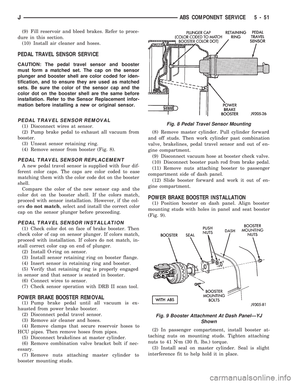
(4) Remove sensor from booster (Fig. 8).
PEDAL TRAVEL SENSOR REPLACEMENT
A new pedal travel sensor is supplied with four dif-
ferent color caps. The caps are color coded to ease
matching them with the color code dot on the booster
shell.
Compare the color of the new sensor cap and the
color dot on the booster shell. If the colors match,
proceed with sensor installation. However, if the col-
orsdo not match, select and install the correct color
cap on the sensor plunger before proceeding.
PEDAL TRAVEL SENSOR INSTALLATION
(1) Check color dot on face of brake booster. Then
check color of cap on sensor plunger. If colors match,
proceed with installation. If colors do not match, in-
stall correct color cap on end of plunger.
(2) Install O-ring on sensor.
(3) Install sensor retaining ring on booster flange.
(4) Insert sensor in retaining ring and booster.
(5) Verify that retaining ring is properly engaged
in sensor and that sensor is seated in booster.
(6) Connect wires to sensor.
(7) Check sensor operation with DRB II scan tool.
POWER BRAKE BOOSTER REMOVAL
(1) Pump brake pedal until all vacuum is ex-
hausted from power brake booster.
(2) Disconnect pedal travel sensor.
(3) Remove air cleaner and hoses.
(4) Remove clamps that secure reservoir hoses to
HCU pipes. Then remove hoses from pipes.
(5) Disconnect brakelines at master cylinder.
(6) Remove combination valve bracket bolt if nec-
essary.
(7) Remove nuts attaching master cylinder to
booster mounting studs.(8) Remove master cylinder. Pull cylinder forward
and off studs. Then work cylinder past combination
valve, brakelines, pedal travel sensor and out of en-
gine compartment.
(9) Disconnect vacuum hose at booster check valve.
(10) Disconnect booster push rod from brake pedal.
(11) Remove nuts attaching booster to passenger
compartment side of dash panel.
(12) Slide booster forward and work it out of en-
gine compartment.
POWER BRAKE BOOSTER INSTALLATION
(1) Position booster on dash panel. Align booster
mounting studs with holes in panel and seat booster
(Fig. 9).
(2) In passenger compartment, install booster at-
taching nuts on mounting studs. Tighten attaching
nuts to 41 Nzm (30 ft. lbs.) torque.
(3) Install seal on master cylinder. Seal is slight
interference fit to help hold it in place.
Fig. 8 Pedal Travel Sensor Mounting
Fig. 9 Booster Attachment At Dash PanelÐYJ
Shown
JABS COMPONENT SERVICE 5 - 51
Page 206 of 1784
PARKING BRAKE LEVER REMOVAL (XJ WITH FULL
CONSOLE)
(1) Release parking brakes, if necessary.
(2) Raise vehicle.
(3) Remove adjusting nut from tensioner rod. Then
temporarily secure equalizer to nearby chassis com-
ponent with wire.
(4) Remove nuts attaching lever support plate to
underside of floorpan.
(5) Lower vehicle.
(6) On models with manual transmission, remove
shift knob, boot and bezel.
(7) On models with automatic transmission, re-
move shift handle cap and remove plunger, spring
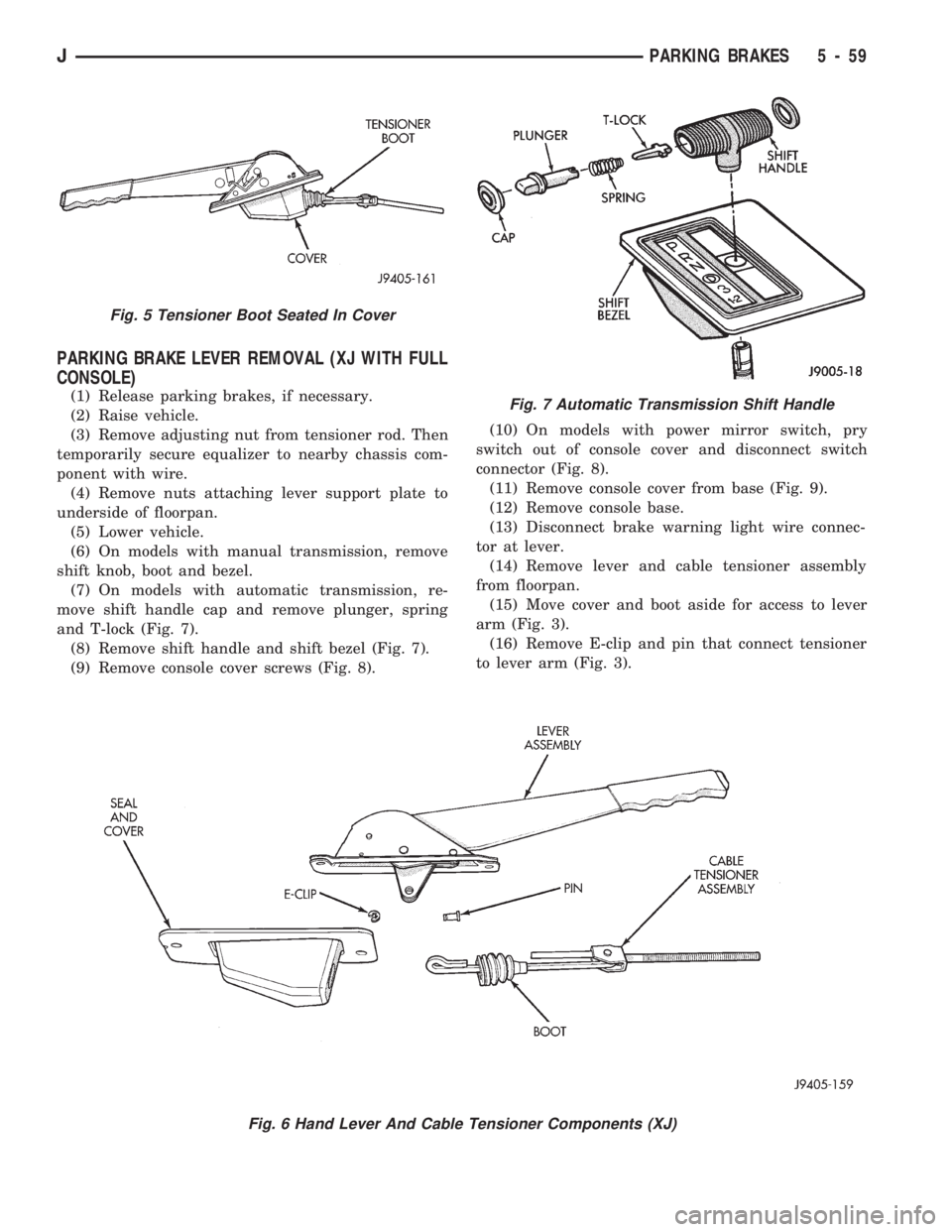
and T-lock (Fig. 7).
(8) Remove shift handle and shift bezel (Fig. 7).
(9) Remove console cover screws (Fig. 8).(10) On models with power mirror switch, pry
switch out of console cover and disconnect switch
connector (Fig. 8).
(11) Remove console cover from base (Fig. 9).
(12) Remove console base.
(13) Disconnect brake warning light wire connec-
tor at lever.
(14) Remove lever and cable tensioner assembly
from floorpan.
(15) Move cover and boot aside for access to lever
arm (Fig. 3).
(16) Remove E-clip and pin that connect tensioner
to lever arm (Fig. 3).
Fig. 6 Hand Lever And Cable Tensioner Components (XJ)
Fig. 5 Tensioner Boot Seated In Cover
Fig. 7 Automatic Transmission Shift Handle
JPARKING BRAKES 5 - 59
Page 207 of 1784
PARKING BRAKE LEVER INSTALLATION (XJ WITH
FULL CONSOLE)
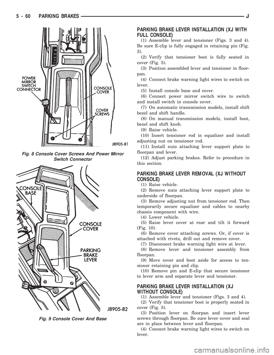
(1) Assemble lever and tensioner (Figs. 3 and 4).
Be sure E-clip is fully engaged in retaining pin (Fig.
3).
(2) Verify that tensioner boot is fully seated in
cover (Fig. 5).
(3) Position assembled lever and tensioner in floor-
pan.
(4) Connect brake warning light wires to switch on
lever.
(5) Install console base and cover.
(6) Connect power mirror switch wire to switch
and install switch in console cover.
(7) On automatic transmission models, install shift
bezel and shift handle.
(8) On manual transmission models, install boot,
bezel and shift knob.
(9) Raise vehicle.
(10) Insert tensioner rod in equalizer and install
adjusting nut on tensioner rod.
(11) Install nuts attaching lever support plate to
floorpan and lever.
(12) Adjust parking brakes. Refer to procedure in
this section.
PARKING BRAKE LEVER REMOVAL (XJ WITHOUT
CONSOLE)
(1) Raise vehicle.
(2) Remove nuts attaching lever support plate to
underside of floorpan.
(3) Remove adjusting nut from tensioner rod. Then
temporarily secure equalizer and cables to nearby
chassis component with wire.
(4) Lower vehicle.
(5) Raise lever cover at rear and tilt it forward
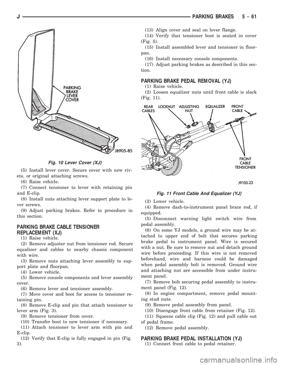
(Fig. 10).
(6) Remove cover attaching screws. Or, if cover is
attached with rivets, drill out and remove cover.
(7) Disconnect brake warning light wire at lever.
(8) Remove lever and tensioner assembly from
floorpan.
(9) Move cover and boot aside for access to ten-
sioner retaining pin and clip.
(10) Remove pin and E-clip that secure tensioner
to lever arm and separate lever and tensioner.
PARKING BRAKE LEVER INSTALLATION (XJ
WITHOUT CONSOLE)
(1) Assemble lever and tensioner (Figs. 3 and 4).
(2) Verify that tensioner boot is properly seated in
cover (Fig. 5).
(3) Position lever on floorpan and insert lever
screws through floorpan. Be sure lever cover and seal
are in place between lever and floorpan.
(4) Connect brake warning light wires to switch on
lever.
Fig. 8 Console Cover Screws And Power Mirror
Switch Connector
Fig. 9 Console Cover And Base
5 - 60 PARKING BRAKESJ
Page 208 of 1784
(5) Install lever cover. Secure cover with new riv-
ets, or original attaching screws.
(6) Raise vehicle.
(7) Connect tensioner to lever with retaining pin
and E-clip.
(8) Install nuts attaching lever support plate to le-
ver screws.
(9) Adjust parking brakes. Refer to procedure in
this section.
PARKING BRAKE CABLE TENSIONER
REPLACEMENT (XJ)
(1) Raise vehicle.
(2) Remove adjuster nut from tensioner rod. Secure
equalizer and cables to nearby chassis component
with wire.
(3) Remove nuts attaching lever assembly to sup-
port plate and floorpan.
(4) Lower vehicle.
(5) Remove console components and lever assembly
cover.
(6) Remove lever and tensioner assembly.
(7) Move cover and boot for access to tensioner re-
taining pin.
(8) Remove E-clip and pin that attach tensioner to
lever arm (Fig. 3).
(9) Remove tensioner from cover.
(10) Transfer boot to new tensioner if necessary.
(11) Attach tensioner to lever arm with pin and
E-clip.
(12) Verify that E-clip is fully engaged in pin (Fig.
3).(13) Align cover and seal on lever flange.
(14) Verify that tensioner boot is seated in cover
(Fig. 5).
(15) Install assembled lever and tensioner in floor-
pan.
(16) Install necessary console components.
(17) Adjust parking brakes as described in this sec-
tion.
PARKING BRAKE PEDAL REMOVAL (YJ)
(1) Raise vehicle.
(2) Loosen equalizer nuts until front cable is slack
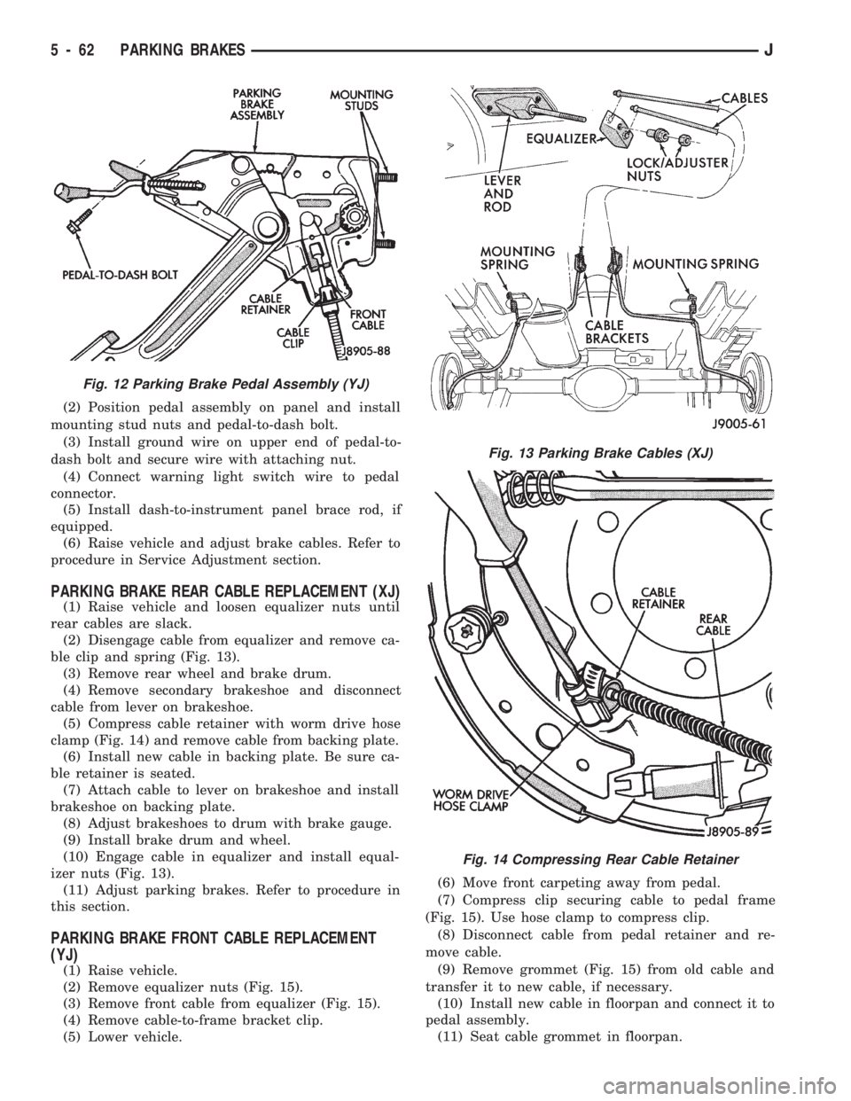
(Fig. 11).
(3) Lower vehicle.
(4) Remove dash-to-instrument panel brace rod, if
equipped.
(5) Disconnect warning light switch wire from
pedal assembly.
(6) On some YJ models, a ground wire may be at-
tached to upper end of bolt that secures parking
brake pedal to instrument panel. Wire is secured
with a nut. Be sure to remove nut and detach ground
wire before proceeding. If this wire is not removed
beforehand, wire and harness could be damaged
when pedal assembly bolt is removed. Ground wire
and attaching nut are accessible from under instru-
ment panel.
(7) Remove bolt securing pedal assembly to instru-
ment panel (Fig. 12).
(8) In engine compartment, remove pedal mount-
ing stud nuts.
(9) Remove pedal assembly from panel.
(10) Disengage front cable from retainer (Fig. 12).
(11) Squeeze cable clip (Fig. 12) and pull cable out
of pedal frame.
(12) Remove pedal assembly.
PARKING BRAKE PEDAL INSTALLATION (YJ)
(1) Connect front cable to pedal retainer.
Fig. 10 Lever Cover (XJ)
Fig. 11 Front Cable And Equalizer (YJ)
JPARKING BRAKES 5 - 61
Page 209 of 1784
(2) Position pedal assembly on panel and install
mounting stud nuts and pedal-to-dash bolt.
(3) Install ground wire on upper end of pedal-to-
dash bolt and secure wire with attaching nut.
(4) Connect warning light switch wire to pedal
connector.
(5) Install dash-to-instrument panel brace rod, if
equipped.
(6) Raise vehicle and adjust brake cables. Refer to
procedure in Service Adjustment section.
PARKING BRAKE REAR CABLE REPLACEMENT (XJ)
(1) Raise vehicle and loosen equalizer nuts until
rear cables are slack.
(2) Disengage cable from equalizer and remove ca-
ble clip and spring (Fig. 13).
(3) Remove rear wheel and brake drum.
(4) Remove secondary brakeshoe and disconnect
cable from lever on brakeshoe.
(5) Compress cable retainer with worm drive hose
clamp (Fig. 14) and remove cable from backing plate.
(6) Install new cable in backing plate. Be sure ca-
ble retainer is seated.
(7) Attach cable to lever on brakeshoe and install
brakeshoe on backing plate.
(8) Adjust brakeshoes to drum with brake gauge.
(9) Install brake drum and wheel.
(10) Engage cable in equalizer and install equal-
izer nuts (Fig. 13).
(11) Adjust parking brakes. Refer to procedure in
this section.
PARKING BRAKE FRONT CABLE REPLACEMENT
(YJ)
(1) Raise vehicle.
(2) Remove equalizer nuts (Fig. 15).
(3) Remove front cable from equalizer (Fig. 15).
(4) Remove cable-to-frame bracket clip.
(5) Lower vehicle.(6) Move front carpeting away from pedal.
(7) Compress clip securing cable to pedal frame
(Fig. 15). Use hose clamp to compress clip.
(8) Disconnect cable from pedal retainer and re-
move cable.
(9) Remove grommet (Fig. 15) from old cable and
transfer it to new cable, if necessary.
(10) Install new cable in floorpan and connect it to
pedal assembly.
(11) Seat cable grommet in floorpan.
Fig. 12 Parking Brake Pedal Assembly (YJ)
Fig. 13 Parking Brake Cables (XJ)
Fig. 14 Compressing Rear Cable Retainer
5 - 62 PARKING BRAKESJ
Page 212 of 1784
BRAKE PEDAL AND BRAKELIGHT SWITCH
INDEX
page page
Brake Pedal Installation.................... 66
Brake Pedal Removal..................... 65
Brake Pedal Service...................... 65
Brakelight Switch Adjustment................ 66Brakelight Switch Installation................ 66
Brakelight Switch Removal................. 66
General Information....................... 65
GENERAL INFORMATION
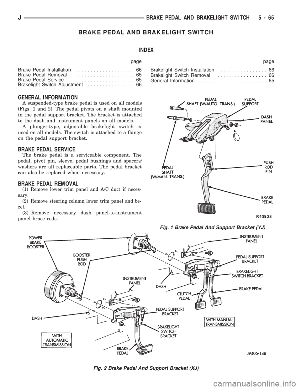
A suspended-type brake pedal is used on all models
(Figs. 1 and 2). The pedal pivots on a shaft mounted
in the pedal support bracket. The bracket is attached
to the dash and instrument panels on all models.
A plunger-type, adjustable brakelight switch is
used on all models. The switch is attached to a flange
on the pedal support bracket.
BRAKE PEDAL SERVICE
The brake pedal is a serviceable component. The
pedal, pivot pin, sleeve, pedal bushings and spacers/
washers are all replaceable parts. The pedal bracket
can also be replaced when necessary.
BRAKE PEDAL REMOVAL
(1) Remove lower trim panel and A/C duct if neces-
sary.
(2) Remove steering column lower trim panel and be-
zel.
(3) Remove necessary dash panel-to-instrument
panel brace rods.
Fig. 1 Brake Pedal And Support Bracket (YJ)
Fig. 2 Brake Pedal And Support Bracket (XJ)
JBRAKE PEDAL AND BRAKELIGHT SWITCH 5 - 65
Page 213 of 1784
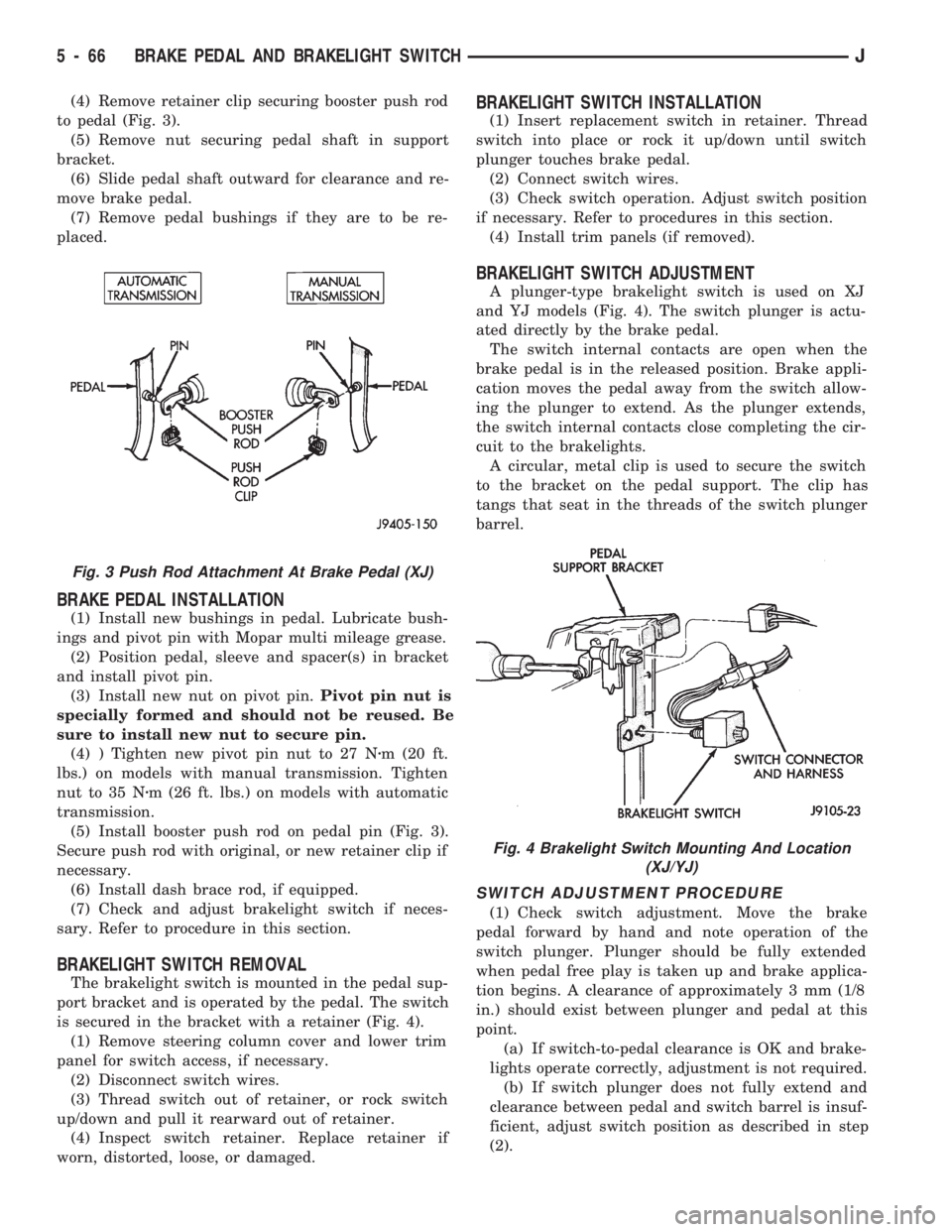
(4) Remove retainer clip securing booster push rod
to pedal (Fig. 3).
(5) Remove nut securing pedal shaft in support
bracket.
(6) Slide pedal shaft outward for clearance and re-
move brake pedal.
(7) Remove pedal bushings if they are to be re-
placed.
BRAKE PEDAL INSTALLATION
(1) Install new bushings in pedal. Lubricate bush-
ings and pivot pin with Mopar multi mileage grease.
(2) Position pedal, sleeve and spacer(s) in bracket
and install pivot pin.
(3) Install new nut on pivot pin.Pivot pin nut is
specially formed and should not be reused. Be
sure to install new nut to secure pin.
(4) ) Tighten new pivot pin nut to 27 Nzm (20 ft.
lbs.) on models with manual transmission. Tighten
nut to 35 Nzm (26 ft. lbs.) on models with automatic
transmission.
(5) Install booster push rod on pedal pin (Fig. 3).
Secure push rod with original, or new retainer clip if
necessary.
(6) Install dash brace rod, if equipped.
(7) Check and adjust brakelight switch if neces-
sary. Refer to procedure in this section.
BRAKELIGHT SWITCH REMOVAL
The brakelight switch is mounted in the pedal sup-
port bracket and is operated by the pedal. The switch
is secured in the bracket with a retainer (Fig. 4).
(1) Remove steering column cover and lower trim
panel for switch access, if necessary.
(2) Disconnect switch wires.
(3) Thread switch out of retainer, or rock switch
up/down and pull it rearward out of retainer.
(4) Inspect switch retainer. Replace retainer if
worn, distorted, loose, or damaged.
BRAKELIGHT SWITCH INSTALLATION
(1) Insert replacement switch in retainer. Thread
switch into place or rock it up/down until switch
plunger touches brake pedal.
(2) Connect switch wires.
(3) Check switch operation. Adjust switch position
if necessary. Refer to procedures in this section.
(4) Install trim panels (if removed).
BRAKELIGHT SWITCH ADJUSTMENT
A plunger-type brakelight switch is used on XJ
and YJ models (Fig. 4). The switch plunger is actu-
ated directly by the brake pedal.
The switch internal contacts are open when the
brake pedal is in the released position. Brake appli-
cation moves the pedal away from the switch allow-
ing the plunger to extend. As the plunger extends,
the switch internal contacts close completing the cir-
cuit to the brakelights.
A circular, metal clip is used to secure the switch
to the bracket on the pedal support. The clip has
tangs that seat in the threads of the switch plunger
barrel.
SWITCH ADJUSTMENT PROCEDURE
(1) Check switch adjustment. Move the brake
pedal forward by hand and note operation of the
switch plunger. Plunger should be fully extended
when pedal free play is taken up and brake applica-
tion begins. A clearance of approximately 3 mm (1/8
in.) should exist between plunger and pedal at this
point.
(a) If switch-to-pedal clearance is OK and brake-
lights operate correctly, adjustment is not required.
(b) If switch plunger does not fully extend and
clearance between pedal and switch barrel is insuf-
ficient, adjust switch position as described in step
(2).
Fig. 3 Push Rod Attachment At Brake Pedal (XJ)
Fig. 4 Brakelight Switch Mounting And Location
(XJ/YJ)
5 - 66 BRAKE PEDAL AND BRAKELIGHT SWITCHJ