1994 JEEP CHEROKEE weight
[x] Cancel search: weightPage 891 of 1784

4.0L ENGINE SERVICE PROCEDURES
INDEX
page page
Camshaft............................... 69
Camshaft Pin Replacement................. 71
Crankshaft Main Bearings.................. 80
Cylinder Block........................... 85
Engine AssemblyÐXJ Vehicles.............. 54
Engine AssemblyÐYJ Vehicles.............. 57
Engine Cylinder Head..................... 60
Engine Cylinder Head Cover................ 59
Engine MountÐRear...................... 52
Engine MountsÐFront..................... 51
General Information....................... 50
Hydraulic Tappets........................ 65
Oil Pan ................................ 72Oil Pump............................... 73
Pistons and Connecting Rods............... 74
Rear Main Oil Seals...................... 84
Rocker Arms............................ 59
Specifications........................... 87
Timing Case Cover....................... 67
Timing Case Cover Oil Seal Replacement...... 67
Timing Chain and Sprockets................ 68
Valve Springs and Oil Seals................ 62
Valve Timing............................ 66
Valves and Valve Springs.................. 63
Vibration Damper........................ 67
GENERAL INFORMATION
The 4.0 Liter (242 CID) six-cylinder engine is an
In-line, lightweight, overhead valve engine (Fig. 1).
This engine is designed for unleaded fuel.
The engine cylinder head has dual quench-type
combustion chambers that create turbulence and fast
burning of the air/fuel mixture. This results in good
fuel economy.
The cylinders are numbered 1 through 6 from front
to rear. The firing order is 1-5-3-6-2-4 (Fig. 2).The crankshaft rotation is clockwise, when viewed
from the front of the engine. The crankshaft rotates
within seven main bearings. The camshaft rotates
within four bearings.
BUILD DATE CODE
The engine Build Date Code is located on a ma-
chined surface on the right side of the cylinder block
between the No.2 and No.3 cylinders (Fig. 3).
The digits of the code identify:
(1) 1st DigitÐThe year (4 = 1994).
(2) 2nd & 3rd DigitsÐThe month (01 - 12).
(3) 4th & 5th DigitsÐThe engine type/fuel system/
compression ratio (MX = A 4.0 Liter (242 CID) 8.7:1
compression ratio engine with a multi-point fuel in-
jection system).
(4) 6th & 7th DigitsÐThe day of engine build (01 -
31).
FOR EXAMPLE:Code * 401MX12 * identifies a
4.0 liter (242 CID) engine with a multi-point fuel in-
jection system, 8.7:1 compression ratio and built on
January 12, 1994.
Fig. 2 Engine Firing Order
Fig. 1 Engine Description
9 - 50 4.0L ENGINEJ
Page 907 of 1784

LEAK-DOWN TEST
After cleaning and inspection, test each tappet for
specified leak-down rate tolerance to ensure zero-lash
operation (Fig. 12).
Swing the weighted arm of the hydraulic valve tap-
pet tester away from the ram of the Leak-Down
Tester 7980.
(1) Place a 7.925-7.950 mm (0.312-0.313 inch) di-
ameter ball bearing on the plunger cap of the tappet.
(2) Lift the ram and position the tappet (with the
ball bearing) inside the tester cup.
(3) Lower the ram, then adjust the nose of the ram
until it contacts the ball bearing. DO NOT tighten
the hex nut on the ram.
(4) Fill the tester cup with hydraulic valve tappet
test oil until the tappet is completely submerged.
(5) Swing the weighted arm onto the push rod and
pump the tappet plunger up and down to remove air.
When the air bubbles cease, swing the weighted arm
away and allow the plunger to rise to the normal po-
sition.
(6) Adjust the nose of the ram to align the pointer
with the SET mark on the scale of the tester and
tighten the hex nut.
(7) Slowly swing the weighted arm onto the push
rod.
(8) Rotate the cup by turning the handle at the
base of the tester clockwise one revolution every 2
seconds.
(9) Observe the leak-down time interval from the
instant the pointer aligns with the START mark on
the scale until the pointer aligns with the 0.125
mark. A normally functioning tappet will require 20-
110 seconds to leak-down. Discard tappets with leak-
down time interval not within this specification.
INSTALLATION
It is not necessary to charge the tappets with en-
gine oil. They will charge themselves within a very
short period of engine operation.(1) Dip each tappet in Mopar Engine Oil Supple-
ment, or equivalent.
(2) Use Hydraulic Valve Tappet Removal/Installa-
tion Tool C-4129-A to install each tappet in the same
bore from where it was originally removed.
(3) Install the exhaust and intake manifolds (refer
to Group 11, Exhaust System and Intake Manifold
for the proper procedure).
(4) Install the engine cylinder head and gasket.
(5) Install the push rods in their original locations.
(6) Install the rocker arms and bridge and pivot
assemblies at their original locations. Loosely install
the capscrews at each bridge.
(7) Tighten the capscrews alternately, one turn at
a time, to avoid damaging the bridges. Tighten the
capscrews to 28 Nzm (21 ft. lbs.) torque.
(8) Pour the remaining Mopar Engine Oil Supple-
ment, or equivalent over the entire valve actuating
assembly. The Mopar Engine Oil Supplement, or
equivalent must remain with the engine oil for at
least 1 609 km (1,000 miles). The oil supplement
need not be drained until the next scheduled oil
change.
(9) Install the engine cylinder head cover.
VALVE TIMING
Disconnect the spark plug wires and remove the
spark plugs.
Remove the engine cylinder head cover.
Remove the capscrews, bridge and pivot assembly,
and rocker arms from above the No.1 cylinder.
Alternately loosen each capscrew, one turn at a
time, to avoid damaging the bridge.
Rotate the crankshaft until the No.6 piston is at
top dead center (TDC) on the compression stroke.
Rotate the crankshaft counterclockwise (viewed
from the front of the engine) 90É.
Install a dial indicator on the end of the No.1 cyl-
inder intake valve push rod. Use rubber tubing to se-
cure the indicator stem on the push rod.
Set the dial indicator pointer at zero.
Rotate the crankshaft clockwise (viewed from the
front of the engine) until the dial indicator pointer
indicates 0.305 mm (0.012 inch) travel distance (lift).
The timing notch index on the vibration damper
should be aligned with the TDC mark on the timing
degree scale.
If the timing notch is more than 13 mm (1/2 inch)
away from the TDC mark in either direction, the
valve timing is incorrect.
If the valve timing is incorrect, the cause may be a
broken camshaft pin. It is not necessary to replace
the camshaft because of pin failure. A spring pin is
available for service replacement.
Fig. 12 Leak-Down Tester 7980
9 - 66 4.0L ENGINEJ
Page 921 of 1784
CAUTION: Ensure that connecting rod bolts DO
NOT scratch the crankshaft journals or cylinder
walls. Short pieces of rubber hose slipped over the
connecting rod bolts will provide protection during
installation.
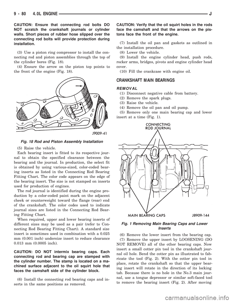
(3) Use a piston ring compressor to install the con-
necting rod and piston assemblies through the top of
the cylinder bores (Fig. 18).
(4) Ensure the arrow on the piston top points to
the front of the engine (Fig. 18).
(5) Raise the vehicle.
Each bearing insert is fitted to its respective jour-
nal to obtain the specified clearance between the
bearing and the journal. In production, the select fit
is obtained by using various-sized, color-coded bear-
ing inserts as listed in the Connecting Rod Bearing
Fitting Chart. The color code appears on the edge of
the bearing insert. The size is not stamped on inserts
used for production of engines.
The rod journal is identified during the engine pro-
duction by a color-coded paint mark on the adjacent
cheek or counterweight toward the flange (rear) end
of the crankshaft. The color codes used to indicate
journal sizes are listed in the Connecting Rod Bear-
ing Fitting Chart.
When required, upper and lower bearing inserts of
different sizes may be used as a pair (refer to Con-
necting Rod Bearing Fitting Chart). A standard size
insert is sometimes used in combination with a 0.025
mm (0.001 inch) undersize insert to reduce clearance
0.013 mm (0.0005 inch).
CAUTION: DO NOT intermix bearing caps. Each
connecting rod and bearing cap are stamped with
the cylinder number. The stamp is located on a ma-
chined surface adjacent to the oil squirt hole that
faces the camshaft side of the cylinder block.
(6) Install the connecting rod bearing caps and in-
serts in the same positions as removed.CAUTION: Verify that the oil squirt holes in the rods
face the camshaft and that the arrows on the pis-
tons face the front of the engine.
(7) Install the oil pan and gaskets as outlined in
the installation procedure.
(8) Lower the vehicle.
(9) Install the engine cylinder head, push rods,
rocker arms, bridges, pivots and engine cylinder head
cover.
(10) Fill the crankcase with engine oil.
CRANKSHAFT MAIN BEARINGS
REMOVAL
(1) Disconnect negative cable from battery.
(2) Remove the spark plugs.
(3) Raise the vehicle.
(4) Remove the oil pan and oil pump.
(5) Remove only one main bearing cap and lower
insert at a time (Fig. 1).
(6) Remove the lower insert from the bearing cap.
(7) Remove the upper insert by LOOSENING (DO
NOT REMOVE) all of the other bearing caps. Now
insert a small cotter pin tool in the crankshaft jour-
nal oil hole. Bend the cotter pin as illustrated to fab-
ricate the tool (Fig. 2). With the cotter pin tool in
place, rotate the crankshaft so that the upper bear-
ing insert will rotate in the direction of its locking
tab. Because there is no hole in the No.3 main jour-
nal, use a tongue depressor or similar soft-faced tool
to remove the bearing insert (Fig. 2). After moving
Fig. 18 Rod and Piston Assembly Installation
Fig. 1 Removing Main Bearing Caps and Lower
Inserts
9 - 80 4.0L ENGINEJ
Page 942 of 1784
FRAME AND BUMPERS
CONTENTS
page page
XJ BUMPERS........................... 3
XJ UNIBODY CONSTRUCTION............. 1YJ BUMPERS AND FRAME ATTACHED
COMPONENTS........................ 14
YJ FRAME............................. 8
XJ UNIBODY CONSTRUCTION
INDEX
page page
Collision Damage Torque................... 1General Information........................ 1
GENERAL INFORMATION
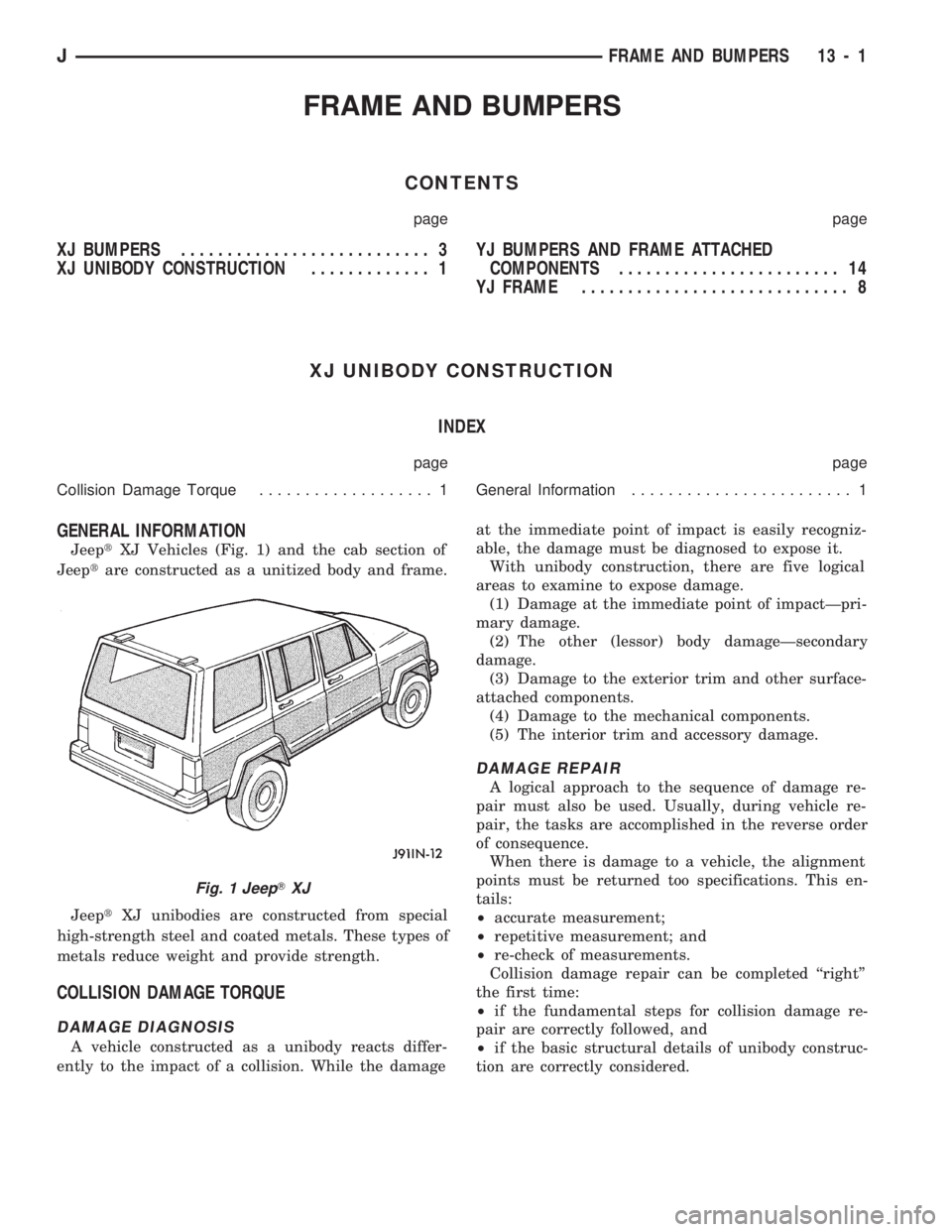
JeeptXJ Vehicles (Fig. 1) and the cab section of
Jeeptare constructed as a unitized body and frame.
JeeptXJ unibodies are constructed from special
high-strength steel and coated metals. These types of
metals reduce weight and provide strength.
COLLISION DAMAGE TORQUE
DAMAGE DIAGNOSIS
A vehicle constructed as a unibody reacts differ-
ently to the impact of a collision. While the damageat the immediate point of impact is easily recogniz-
able, the damage must be diagnosed to expose it.
With unibody construction, there are five logical
areas to examine to expose damage.
(1) Damage at the immediate point of impactÐpri-
mary damage.
(2) The other (lessor) body damageÐsecondary
damage.
(3) Damage to the exterior trim and other surface-
attached components.
(4) Damage to the mechanical components.
(5) The interior trim and accessory damage.
DAMAGE REPAIR
A logical approach to the sequence of damage re-
pair must also be used. Usually, during vehicle re-
pair, the tasks are accomplished in the reverse order
of consequence.
When there is damage to a vehicle, the alignment
points must be returned too specifications. This en-
tails:
²accurate measurement;
²repetitive measurement; and
²re-check of measurements.
Collision damage repair can be completed ``right''
the first time:
²if the fundamental steps for collision damage re-
pair are correctly followed, and
²if the basic structural details of unibody construc-
tion are correctly considered.
Fig. 1 JeepTXJ
JFRAME AND BUMPERS 13 - 1
Page 951 of 1784

CONSTRUCTION
The frame is constructed of high-strength channel
steel siderails and crossmembers. The crossmembers
join the siderails and retain them in alignment in re-
lation to each other. This provides resistance to
frame twists and strains.
FRAME ALIGNMENT
INCORRECT ALIGNMENT
Incorrect frame alignment is usually a result of:
²collision impact, or
²the vehicle being operated with excessive loads, or
²loads not positioned in a properly distributed man-
ner on the vehicle.
A mis-aligned frame will affect front axle and/or
rear axle alignment. It can cause excessive wear and
mechanical failures in the powertrain. Window glass
cracks and door opening/closing problems. Vehicle
performance can also be impaired.
RE-ALIGNMENT
With collision damage, it is important that the ex-
istence of any frame alignment damage be deter-
mined. If necessary, the frame should be correctly re-
aligned. Refer to the reference dimensions listed on
frame alignment dimension chart (Fig. 4).
FRAME INSPECTION/MEASUREMENTS
INSPECTION
Before proceeding with measurements, inspect all
components for visible damage and other metal dam-
age. Also, inspect all connections for loose and miss-
ing hardware.
All damaged areas must be repaired and/or the
components replaced, as necessary.
MEASUREMENTS
Measure the frame for mis-alignment with the
body attached to the frame. Figure 4 provides the
alignment reference dimensions. The following infor-
mation applies to all measurements.
(1) Place the vehicle on a level surface.
(2) If the vehicle is loaded, ensure that the vehicle
weight plus the payload does not exceed the gross ve-
hicle weight rating. Also, ensure that the load is dis-
tributed in the vehicle as evenly as possible.
(3) Measure the tire inflation pressures and adjust
the pressure, if necessary.
HORIZONTAL OR DIAGONAL FRAME MEASUREMENTS
Determine the frame horizontal non-square devia-
tion(s) according to the following procedure.
(1) Select several reference points along one frame
siderail, preferably at the crossmember junctions.(2) Transfer these reference points to the surface/
floor with a plumb bob. Paper sheets can be attached
to the surface below the reference points for better
measurement accuracy.
(3) Locate the reference points on the other frame
siderail and transfer them to the surface/floor with
the same procedure as above.
(4) Move the vehicle away and measure between
all the reference points diagonally from and parallel
to the siderails (Fig. 5). The measurements should
not differ by more than 6 mm (1/4 in).
(5) Measure the distance between the two front
reference points and the distance between the two
rear reference points. Divide each distance in half
and indicate the two half-way points on the surface/
floor. Designate the front point as ``1'' and the rear
point as ``2'' (Fig. 5).
(6) Place a chalk-line between points 1 and 2 and
``snap'' the string.
(7) Determine how close the center line is to the
diagonal intersection points A, B, C, D, E, and F in
Figure 5.
(8) The reference marks on the surface/floor will
provide an illustrated indication of the degree of
frame misalignment.
(9) A reference point transferred from one frame
siderail may be 3 mm (1/8 in) ahead or behind the
reference point from the opposite siderail.
(10) Frame bow to the side should not exceed 3
mm per 2,540 mm (1/8 inch per 100 inches) in
length.
(11) The overall width of the frame should not
vary more than 3 mm (1/8 in) from reference point-
to-reference point.
(12) Repeat steps (1) through (11) after straighten-
ing the frame to evaluate the effectiveness.
TWIST AND PARALLEL FRAME MEASUREMENTS
Determine the amount of frame twist and siderail
deviation according to the following procedure.
(1) Mark the vertical measurement reference
points under the frame siderails at 305-mm (12-in)
intervals starting at the rear frame crossmember.
(2) Measure the vertical distance up from a level
surface to each reference point located under the left
and right frame siderails.
(3) The distance to a reference point under one
frame siderail should be 3 mm (1/8 in) greater or less
than the point under the opposite siderail.
(4) Plot the measured vertical distances to scale on
a sheet of graph paper. Plot the distances so that the
frame siderails are located adjacent to each other.
Join the vertical distance points.
13 - 10 FRAME AND BUMPERSJ
Page 1025 of 1784
shaft must be able to change operating angles when
going over various road surfaces. This is done
through universal joints, which permit the propeller
shaft to operate at different angles. The slip joints (or
yokes) permit contraction or expansion (Fig. 1,2).
Tubular propeller shafts are balanced by the man-
ufacturer with weights spot welded to the tube.
The propeller shaft is designed and built with the
yoke lugs in line with each other which is called
phasing. This design produces the smoothest running
condition, an out of phase shaft can cause a vibra-
tion.
Before undercoating a vehicle, the propeller
shaft and the U-joints should be covered. This
will prevent the undercoating from causing an
unbalanced condition and vibration.
CAUTION: Use exact replacement hardware for at-
taching the propeller shafts. The specified torque
must always be applied when tightening the fasten-
ers.
UNIVERSAL JOINTS
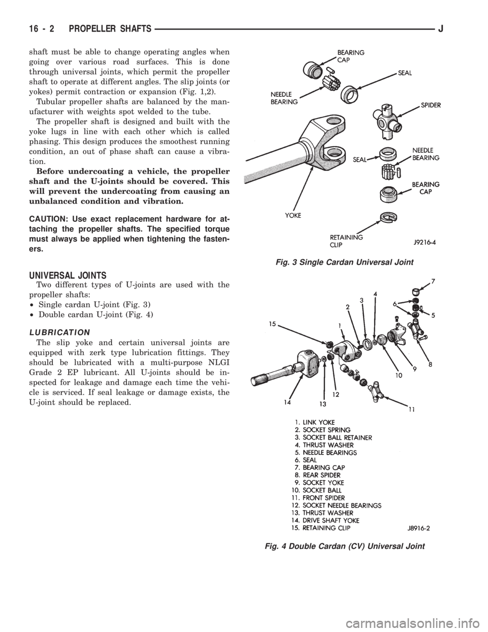
Two different types of U-joints are used with the
propeller shafts:
²Single cardan U-joint (Fig. 3)
²Double cardan U-joint (Fig. 4)
LUBRICATION
The slip yoke and certain universal joints are
equipped with zerk type lubrication fittings. They
should be lubricated with a multi-purpose NLGI
Grade 2 EP lubricant. All U-joints should be in-
spected for leakage and damage each time the vehi-
cle is serviced. If seal leakage or damage exists, the
U-joint should be replaced.
Fig. 3 Single Cardan Universal Joint
Fig. 4 Double Cardan (CV) Universal Joint
16 - 2 PROPELLER SHAFTSJ
Page 1026 of 1784
SERVICE DIAGNOSIS/PROCEDURES
INDEX
page page
Runout................................. 4
Unbalance............................... 3Universal Joint Angle Measurement............ 4
Vibration................................ 3
VIBRATION
Tires that are out-of-round or wheels that are un-
balanced will cause a low frequency vibration. Refer
to Group 22, Wheels and Tires for additional infor-
mation.
Brake drums that are unbalanced will cause a
harsh, low frequency vibration. Refer to Group 5,
Brakes for additional information.
Driveline vibration can also result from loose or
damaged engine mounts. Refer to Group 21, Trans-
missions for additional information.
Propeller shaft vibration will increase as the vehi-
cle speed is increased. A vibration that occurs within
a specific speed range is not caused by propeller
shaft unbalance. Defective universal joints or an in-
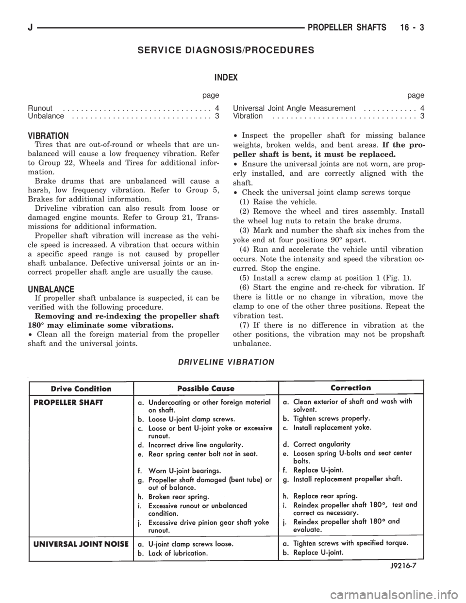
correct propeller shaft angle are usually the cause.
UNBALANCE
If propeller shaft unbalance is suspected, it can be
verified with the following procedure.
Removing and re-indexing the propeller shaft
180É may eliminate some vibrations.
²Clean all the foreign material from the propeller
shaft and the universal joints.²Inspect the propeller shaft for missing balance
weights, broken welds, and bent areas.If the pro-
peller shaft is bent, it must be replaced.
²Ensure the universal joints are not worn, are prop-
erly installed, and are correctly aligned with the
shaft.
²Check the universal joint clamp screws torque
(1) Raise the vehicle.
(2) Remove the wheel and tires assembly. Install
the wheel lug nuts to retain the brake drums.
(3) Mark and number the shaft six inches from the
yoke end at four positions 90É apart.
(4) Run and accelerate the vehicle until vibration
occurs. Note the intensity and speed the vibration oc-
curred. Stop the engine.
(5) Install a screw clamp at position 1 (Fig. 1).
(6) Start the engine and re-check for vibration. If
there is little or no change in vibration, move the
clamp to one of the other three positions. Repeat the
vibration test.
(7) If there is no difference in vibration at the
other positions, the vibration may not be propshaft
unbalance.
DRIVELINE VIBRATION
JPROPELLER SHAFTS 16 - 3
Page 1183 of 1784
(5) Line pressure should be 54-60 psi (372-414
kPa) with throttle lever forward and gradually in-
crease to 90-96 psi (620-662 kPa) as lever is moved
rearward.
Test Three-Transmission In D Range
This test checks pressure regulation and con-
dition of the front and rear clutch circuits.
Both test gauges are required for this test.
(1) Connect one test gauge to line pressure port
and other gauge to front servo pressure port (Fig. 4).
Either gauge can be used at either port.
(2) Start and run engine at 1600 rpm.
(3) Move selector lever two detents rearward from
full forward position. This is D range.
(4) Read pressures on both gauges as transmission
throttle lever is moved from full forward to full rear-
ward position.
(5) Line pressure should be 54-60 psi (372-414
kPa) with throttle lever forward and gradually in-
crease as lever is moved rearward.
(6) Front servo is pressurized only in D range and
should be same as line pressure within 3 psi (21
kPa), up to downshift point.
Test Four-Transmission In Reverse
This test checks pump output, pressure regu-
lation and the front clutch and rear servo cir-
cuits. Use 300 psi Pressure Test Gauge C-3293
for this test.
(1) Connect pressure test gauge to rear servo port
(Fig. 5).
(2) Start and run engine at 1600 rpm for test.
(3) Move valve body selector lever four detents
rearward from full forward position. This is Reverse
range.
(4) Move throttle lever all way forward then all the
way rearward and note gauge readings.
(5) Pressure should be 145 - 175 psi (1000-1207
kPa) with lever forward and increase to 230 - 280 psi
(1586-1931 kPa) as lever is moved rearward.
Test Five-Governor Pressure
This test checks governor operation by mea-
suring governor pressure response to changes
in engine speed. It is usually not necessary to
check governor operation unless shift speeds
are incorrect or if the transmission will not
shift up or down. Use 100 psi Pressure Test
Gauge C-3292 for this test.
(1) Connect test gauge to governor pressure port
(Figs. 5 and 6).
(2) Move selector lever to D range.
(3) Apply service brakes. Start and run engine at
curb idle speed and note pressure. At idle and with
wheels stopped, pressure should be zero to 1-1/2 psi
maximum. If pressure exceeds this figure, governor
valve or weights are sticking open.(4) Slowly increase engine speed and observe
speedometer and pressure test gauge. Governor pres-
sure should increase in proportion to vehicle speed
(approximately 1 psi for every 1 mph shown on
speedometer).
(5) Governor pressure rise should be smooth and
drop back to 0 to 1-1/2 psi when throttle is closed
and wheels are stopped.
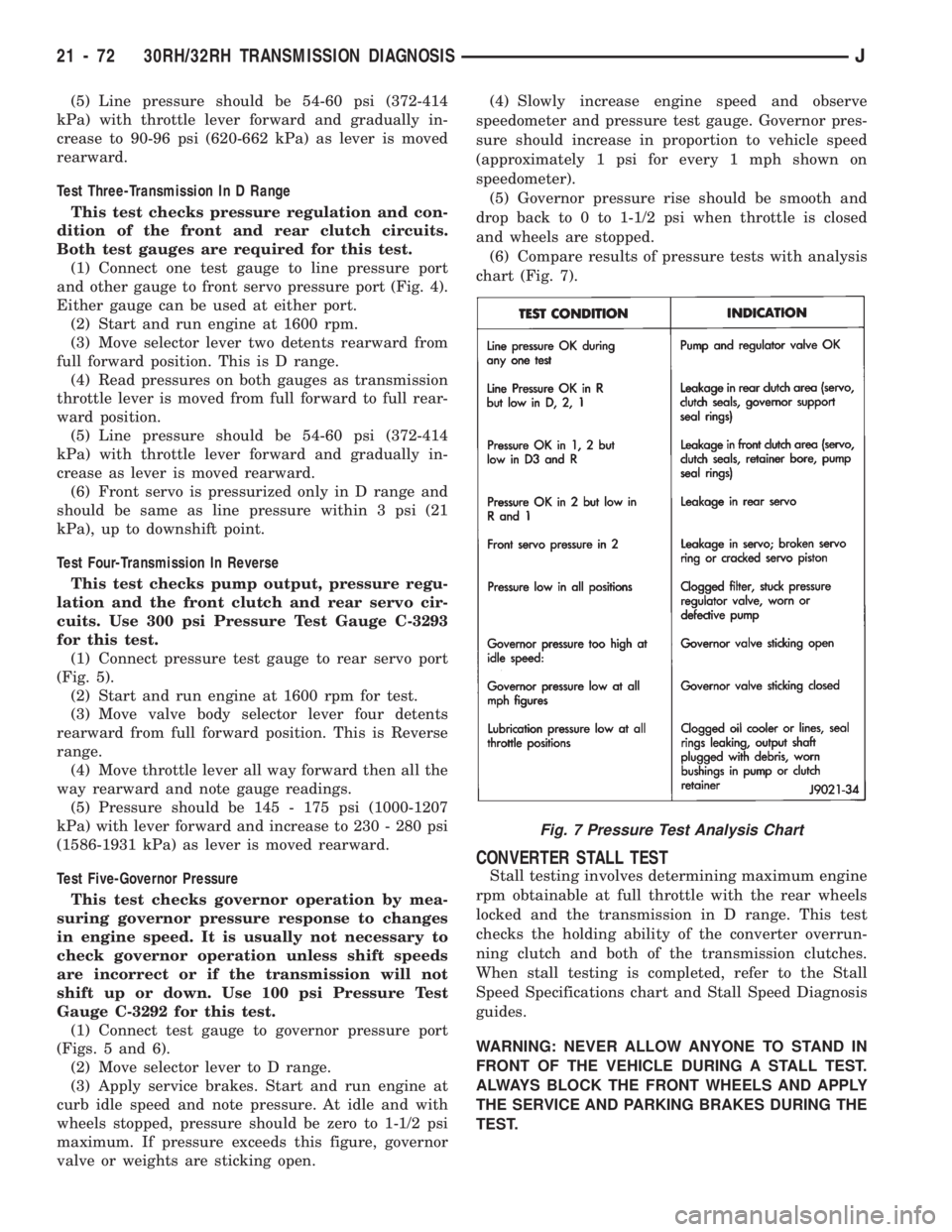
(6) Compare results of pressure tests with analysis
chart (Fig. 7).
CONVERTER STALL TEST
Stall testing involves determining maximum engine
rpm obtainable at full throttle with the rear wheels
locked and the transmission in D range. This test
checks the holding ability of the converter overrun-
ning clutch and both of the transmission clutches.
When stall testing is completed, refer to the Stall
Speed Specifications chart and Stall Speed Diagnosis
guides.
WARNING: NEVER ALLOW ANYONE TO STAND IN
FRONT OF THE VEHICLE DURING A STALL TEST.
ALWAYS BLOCK THE FRONT WHEELS AND APPLY
THE SERVICE AND PARKING BRAKES DURING THE
TEST.
Fig. 7 Pressure Test Analysis Chart
21 - 72 30RH/32RH TRANSMISSION DIAGNOSISJ