Page 1669 of 1784

(18) Disconnect the charging hoses from the ser-
vice valves.
COMPRESSOR OIL LEVEL
The compressor oil level must be checked and ad-
justed if the system has been discharged rapidly, or
when a component has been replaced. If a replace-
ment compressor is being installed, it must be filled
with new compressor oil (Suniso 5GS, or equivalent).
The normal quantity of oil required for the com-
pressor and entire system is 136 ml (4.6 fluid oz.) for
SD 709 compressor. DO NOT overfill the compressor.
Excessive amounts of oil in the system will hinder
compressor operation and reduce A/C performance.
CAUTION: The compressor is a high speed unit.
Satisfactory operation is dependent on sufficient lu-
brication; however, excess oil will hinder A/C per-
formance.
Two oil level checking procedures are necessary.
Use Procedure (A) when the compressor is being re-
placed and the system was discharged properly (no
oil loss). Use Procedure (B) for routine maintenance
or when checking oil level after replacing a system
component.
In cases where rapid loss of refrigerant and oil
occurred, the system must be evacuated and
purged. Then the compressor must be filled with
the necessary amount of oil to fill the entire sys-
tem.
PROCEDURE A
(1) Remove the oil filler plug, discharge cap and
suction port caps from the original and replacement
compressor.
(2) Use a clean container to drain the oil from the
replacement compressor. Drain the oil through the
oil filler plug hole, the discharge and suction. Then
rotate clutch front plate several times to push the oil
on cylinder out to discharge chamber of cylinder
head and drain the oil from discharge port.
(3) Drain the oil from the original compressor into
a measuring cup or graduated beaker in the same
way as Step 2. Note the amount of oil drained.
(4) Fill the replacement compressor with the same
amount of oil drained from the original compressor
plus 30 ml (1 fluid oz.).
FOR EXAMPLE:ÐIf the old compressor contained
103.5 ml (3.5 fluid oz.) of oil, fill the replacement
compressor with a total of 133 ml (4.5 fluid oz.) of oil.
PROCEDURE B
(1) Start the engine and operate the engine at idle.
(2) Operate the air conditioning system for 10 min-
utes to return the maximum amount of oil in the sys-
tem to the compressor.(3) Stop the engine and disconnect the magnetic
clutch feed wire.
(4) Front-seat the discharge and suction service
valves.
(5) Determine the mounting angle.
(a) Position an Angle Gauge across the flat sur-
faces of the front mounting ears.
(b) Center the bubble.
(c) Read the mounting angle to the closest de-
gree.
(d) These vehicles should have 0É mounting an-
gle.
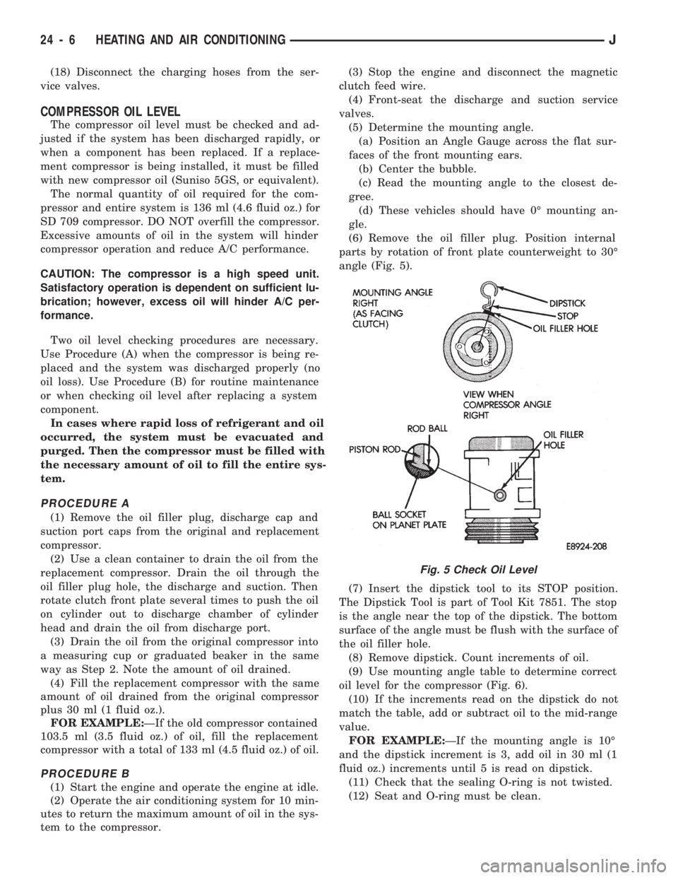
(6) Remove the oil filler plug. Position internal
parts by rotation of front plate counterweight to 30É
angle (Fig. 5).
(7) Insert the dipstick tool to its STOP position.
The Dipstick Tool is part of Tool Kit 7851. The stop
is the angle near the top of the dipstick. The bottom
surface of the angle must be flush with the surface of
the oil filler hole.
(8) Remove dipstick. Count increments of oil.
(9) Use mounting angle table to determine correct
oil level for the compressor (Fig. 6).
(10) If the increments read on the dipstick do not
match the table, add or subtract oil to the mid-range
value.
FOR EXAMPLE:ÐIf the mounting angle is 10É
and the dipstick increment is 3, add oil in 30 ml (1
fluid oz.) increments until 5 is read on dipstick.
(11) Check that the sealing O-ring is not twisted.
(12) Seat and O-ring must be clean.
Fig. 5 Check Oil Level
24 - 6 HEATING AND AIR CONDITIONINGJ
Page 1735 of 1784

INTRODUCTION
CONTENTS
page page
DESIGNATIONS, LABELS/PLATES, CODES
AND DIMENSIONS..................... 1SPECIFICATIONS........................ 8
DESIGNATIONS, LABELS/PLATES, CODES AND DIMENSIONS
INDEX
page page
Engine and Transmission/Transfer Case Identification.3
International Vehicle Control and Display Symbols . 3
Major Component Identification............... 3
Tire Inflation Pressure Label................. 3
Vehicle Code Plate........................ 2Vehicle Designations....................... 1
Vehicle Dimension Data.................... 3
Vehicle Identification Number (VIN) Plate....... 1
Vehicle Load Data........................ 3
Vehicle Safety Certification Label............. 1
VEHICLE DESIGNATIONS
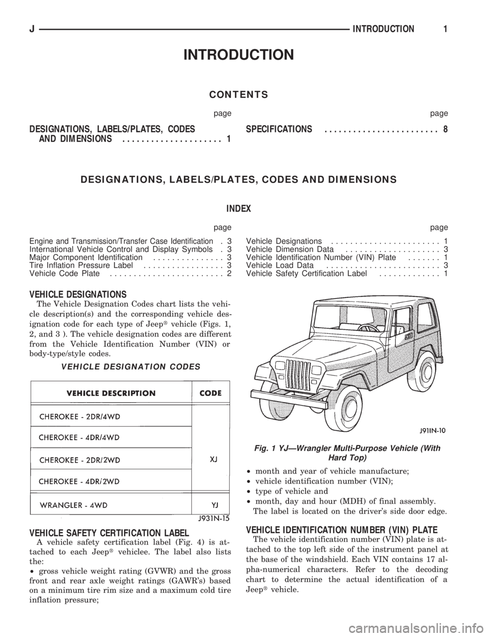
The Vehicle Designation Codes chart lists the vehi-
cle description(s) and the corresponding vehicle des-
ignation code for each type of Jeeptvehicle (Figs. 1,
2, and 3 ). The vehicle designation codes are different
from the Vehicle Identification Number (VIN) or
body-type/style codes.
VEHICLE SAFETY CERTIFICATION LABEL
A vehicle safety certification label (Fig. 4) is at-
tached to each Jeeptvehiclee. The label also lists
the:
²gross vehicle weight rating (GVWR) and the gross
front and rear axle weight ratings (GAWR's) based
on a minimum tire rim size and a maximum cold tire
inflation pressure;²month and year of vehicle manufacture;
²vehicle identification number (VIN);
²type of vehicle and
²month, day and hour (MDH) of final assembly.
The label is located on the driver's side door edge.
VEHICLE IDENTIFICATION NUMBER (VIN) PLATE
The vehicle identification number (VIN) plate is at-
tached to the top left side of the instrument panel at
the base of the windshield. Each VIN contains 17 al-
pha-numerical characters. Refer to the decoding
chart to determine the actual identification of a
Jeeptvehicle.
VEHICLE DESIGNATION CODES
Fig. 1 YJÐWrangler Multi-Purpose Vehicle (With
Hard Top)
JINTRODUCTION1
Page 1737 of 1784

If there is not enough space left in the row for all
of the 6-digit SEC code (if used):
²the unused space will remain blank, and
²the code will be listed in the next row.
The last nine positions of row 7 will contain a 2-digit
code, when applicable, and a 6-digit gateline serial
number (same as the last 6 numbers of the VIN).
The last code imprinted on a vehicle code plate will
be followed by the imprinted word END. When two
vehicle code plates are required, the last available
spaces on the first plate will be imprinted with the
letters CTD (for continued).
When a second vehicle code plate is necessary, the
first four spaces on each row will not be used because
of the plate overlap.
ENGINE AND TRANSMISSION/TRANSFER CASE
IDENTIFICATION
When required, refer to Group 9ÐEngines for allengine identification data. Refer to Group 21ÐTrans-
missions for all transmission/transfer case identifica-
tion data.
MAJOR COMPONENT IDENTIFICATION
When required, refer to the applicable service infor-
mation group for major component identification data.
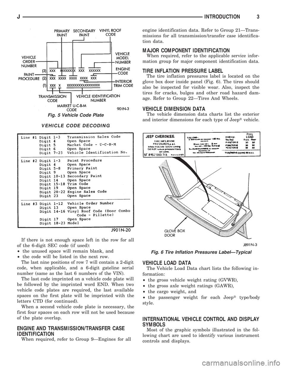
TIRE INFLATION PRESSURE LABEL
The tire inflation pressures label is located on the
glove box door inside panel (Fig. 6). The tires should
also be inspected for visible wear. Also, inspect the
tires for cracks, bulges and other road hazard dam-
age. Refer to Group 22ÐTires And Wheels.
VEHICLE DIMENSION DATA
The vehicle dimension data charts list the exterior
and interior dimensions for each type of Jeeptvehicle.
VEHICLE LOAD DATA
The Vehicle Load Data chart lists the following in-
formation:
²the gross vehicle weight rating (GVWR),
²the gross axle weight ratings (GAWR),
²the cargo weight, and
²the passenger weight for each Jeepttype/body
style.
INTERNATIONAL VEHICLE CONTROL AND DISPLAY
SYMBOLS
Most of the graphic symbols illustrated in the fol-
lowing chart are used to identify various instrument
controls and displays.
Fig. 5 Vehicle Code Plate
VEHICLE CODE DECODING
Fig. 6 Tire Inflation Pressures LabelÐTypical
JINTRODUCTION3