1994 JEEP CHEROKEE weight
[x] Cancel search: weightPage 1213 of 1784
GOVERNOR DISASSEMBLY
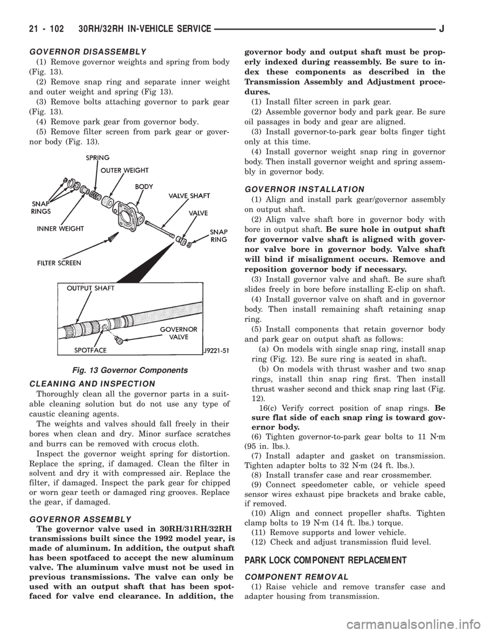
(1) Remove governor weights and spring from body
(Fig. 13).
(2) Remove snap ring and separate inner weight
and outer weight and spring (Fig 13).
(3) Remove bolts attaching governor to park gear
(Fig. 13).
(4) Remove park gear from governor body.
(5) Remove filter screen from park gear or gover-
nor body (Fig. 13).
CLEANING AND INSPECTION
Thoroughly clean all the governor parts in a suit-
able cleaning solution but do not use any type of
caustic cleaning agents.
The weights and valves should fall freely in their
bores when clean and dry. Minor surface scratches
and burrs can be removed with crocus cloth.
Inspect the governor weight spring for distortion.
Replace the spring, if damaged. Clean the filter in
solvent and dry it with compressed air. Replace the
filter, if damaged. Inspect the park gear for chipped
or worn gear teeth or damaged ring grooves. Replace
the gear, if damaged.
GOVERNOR ASSEMBLY
The governor valve used in 30RH/31RH/32RH
transmissions built since the 1992 model year, is
made of aluminum. In addition, the output shaft
has been spotfaced to accept the new aluminum
valve. The aluminum valve must not be used in
previous transmissions. The valve can only be
used with an output shaft that has been spot-
faced for valve end clearance. In addition, thegovernor body and output shaft must be prop-
erly indexed during reassembly. Be sure to in-
dex these components as described in the
Transmission Assembly and Adjustment proce-
dures.
(1) Install filter screen in park gear.
(2) Assemble governor body and park gear. Be sure
oil passages in body and gear are aligned.
(3) Install governor-to-park gear bolts finger tight
only at this time.
(4) Install governor weight snap ring in governor
body. Then install governor weight and spring assem-
bly in governor body.
GOVERNOR INSTALLATION
(1) Align and install park gear/governor assembly
on output shaft.
(2) Align valve shaft bore in governor body with
bore in output shaft.Be sure hole in output shaft
for governor valve shaft is aligned with gover-
nor valve bore in governor body. Valve shaft
will bind if misalignment occurs. Remove and
reposition governor body if necessary.
(3) Install governor valve and shaft. Be sure shaft
slides freely in bore before installing E-clip on shaft.
(4) Install governor valve on shaft and in governor
body. Then install remaining shaft retaining snap
ring.
(5) Install components that retain governor body
and park gear on output shaft as follows:
(a) On models with single snap ring, install snap
ring (Fig. 12). Be sure ring is seated in shaft.
(b) On models with thrust washer and two snap
rings, install thin snap ring first. Then install
thrust washer second and thick snap ring last (Fig.
12).
16(c) Verify correct position of snap rings.Be
sure flat side of each snap ring is toward gov-
ernor body.
(6) Tighten governor-to-park gear bolts to 11 Nzm
(95 in. lbs.).
(7) Install adapter and gasket on transmission.
Tighten adapter bolts to 32 Nzm (24 ft. lbs.).
(8) Install transfer case and rear crossmember.
(9) Connect speedometer cable, or vehicle speed
sensor wires exhaust pipe brackets and brake cable,
if removed.
(10) Align and connect propeller shafts. Tighten
clamp bolts to 19 Nzm (14 ft. lbs.) torque.
(11) Remove supports and lower vehicle.
(12) Check and adjust transmission fluid level.
PARK LOCK COMPONENT REPLACEMENT
COMPONENT REMOVAL
(1) Raise vehicle and remove transfer case and
adapter housing from transmission.
Fig. 13 Governor Components
21 - 102 30RH/32RH IN-VEHICLE SERVICEJ
Page 1225 of 1784
(15) Remove oil pump bolts.
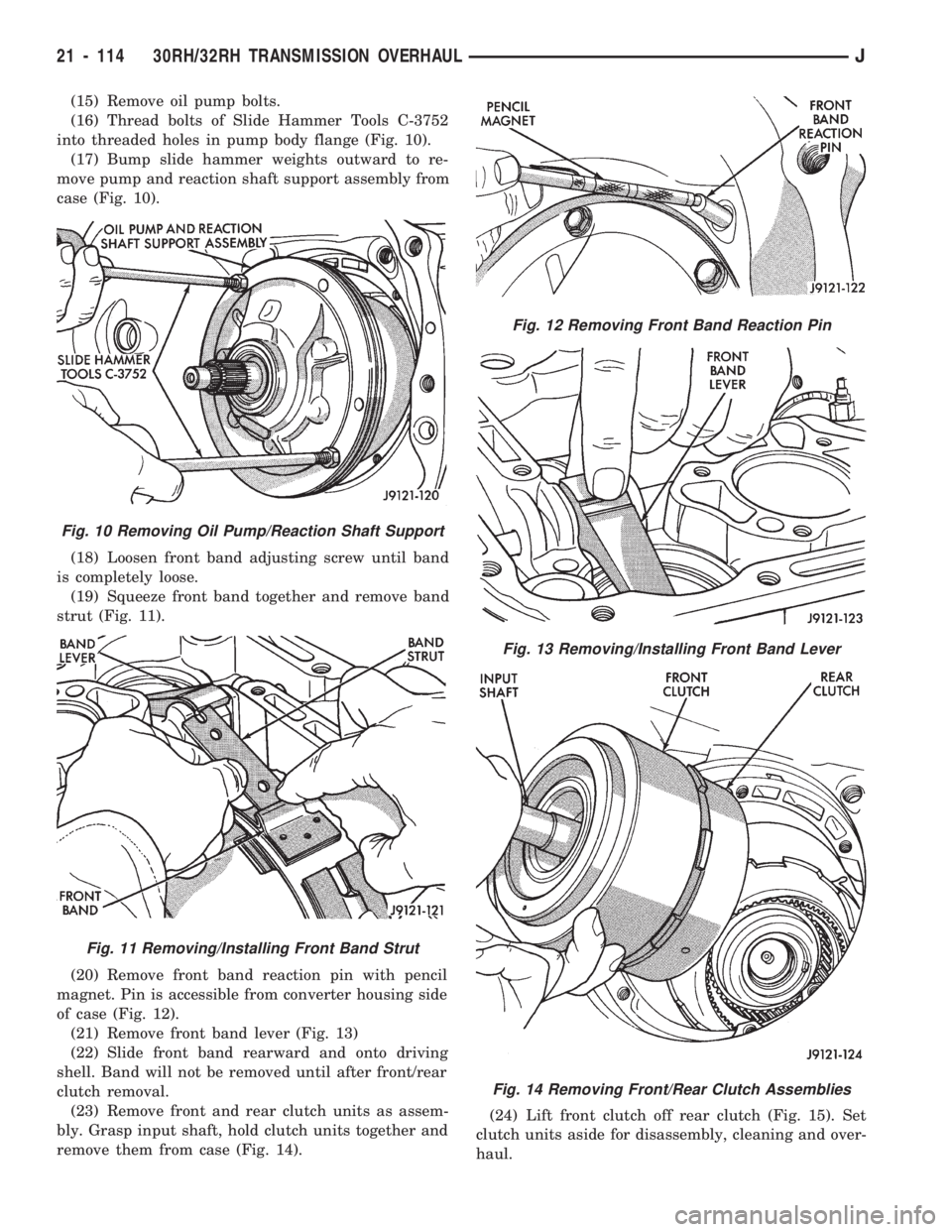
(16) Thread bolts of Slide Hammer Tools C-3752
into threaded holes in pump body flange (Fig. 10).
(17) Bump slide hammer weights outward to re-
move pump and reaction shaft support assembly from
case (Fig. 10).
(18) Loosen front band adjusting screw until band
is completely loose.
(19) Squeeze front band together and remove band
strut (Fig. 11).
(20) Remove front band reaction pin with pencil
magnet. Pin is accessible from converter housing side
of case (Fig. 12).
(21) Remove front band lever (Fig. 13)
(22) Slide front band rearward and onto driving
shell. Band will not be removed until after front/rear
clutch removal.
(23) Remove front and rear clutch units as assem-
bly. Grasp input shaft, hold clutch units together and
remove them from case (Fig. 14).(24) Lift front clutch off rear clutch (Fig. 15). Set
clutch units aside for disassembly, cleaning and over-
haul.
Fig. 10 Removing Oil Pump/Reaction Shaft Support
Fig. 11 Removing/Installing Front Band Strut
Fig. 12 Removing Front Band Reaction Pin
Fig. 13 Removing/Installing Front Band Lever
Fig. 14 Removing Front/Rear Clutch Assemblies
21 - 114 30RH/32RH TRANSMISSION OVERHAULJ
Page 1232 of 1784
GOVERNOR AND PARK GEAR OVERHAUL
GOVERNOR/PARK GEAR DISASSEMBLY
(1) Loosen bolts attaching governor to park gear.
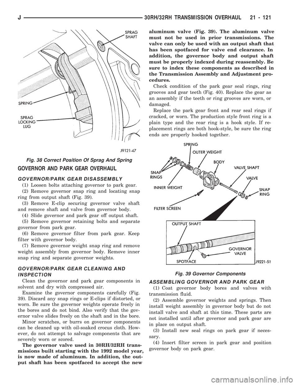
(2) Remove governor snap ring and locating snap
ring from output shaft (Fig. 39).
(3) Remove E-clip securing governor valve shaft
and remove shaft and valve from governor body.
(4) Slide governor and park gear off output shaft.
(5) Remove governor retaining bolts and separate
governor from park gear.
(6) Remove governor filter from park gear. Keep
filter with governor body.
(7) Remove governor weight snap ring and remove
weight assembly from governor body. Remove inner
snap ring and separate governor weights.
GOVERNOR/PARK GEAR CLEANING AND
INSPECTION
Clean the governor and park gear components in
solvent and dry with compressed air.
Examine the governor components carefully (Fig.
39). Discard any snap rings or E-clips if distorted, or
worn. Be sure the governor weights operate freely in
the bores and do not bind. Also verify that the gov-
ernor valve slides freely on the shaft and in the bore.
Minor scratches, or burrs on governor components
can be cleaned up with oil-soaked crocus cloth. How-
ever, do not attempt to salvage components that are
severely worn or scored.
The governor valve used in 30RH/32RH trans-
missions built starting with the 1992 model year,
is now made of aluminum. In addition, the out-
put shaft has been spotfaced to accept the newaluminum valve (Fig. 39). The aluminum valve
must not be used in prior transmissions. The
valve can only be used with an output shaft that
has been spotfaced for valve end clearance. In
addition, the governor body and output shaft
must be properly indexed during reassembly. Be
sure to index these components as described in
the Transmission Assembly and Adjustment pro-
cedures.
Check condition of the park gear seal rings, ring
grooves and gear teeth (Fig. 40). Replace the gear as
an assembly if the teeth or ring grooves are worn, or
damaged.
Replace the park gear front and rear seal rings if
cracked, or worn. The production style front ring is a
plain type and the rear ring is a hook style. If re-
placement rings are both hook-style, be sure the ring
ends are properly hooked together.ASSEMBLING GOVERNOR AND PARK GEAR
(1) Coat governor body bores and valves with
transmission fluid.
(2) Assemble governor weights and springs. Then
install weight assembly in governor body but do not
install valve and shaft at this time. These parts are
not installed until after governor and park gear are
in place on output shaft.
(3) Install new seal rings on park gear if neces-
sary.
(4) Insert filter screen in park gear and position
governor body on park gear.
Fig. 38 Correct Position Of Sprag And Spring
Fig. 39 Governor Components
J30RH/32RH TRANSMISSION OVERHAUL 21 - 121
Page 1261 of 1784
GOVERNOR AND PARK GEAR INSTALLATION
(1) Lubricate governor components and park gear
seal rings with transmission fluid.
(2) Install governor filter in park gear and install
governor body on gear. Align governor body on gear
using marks made at disassembly.
(3) Install new seal rings on hub of park gear if
necessary. Be sure ring (or rings) with hooked ends
are properly connected.
(4) Install governor weight assembly in governor
body. Be sure governor weight snap rings are se-
curely seated.
(5) Align and install governor/park gear assembly
on output shaft as follows:
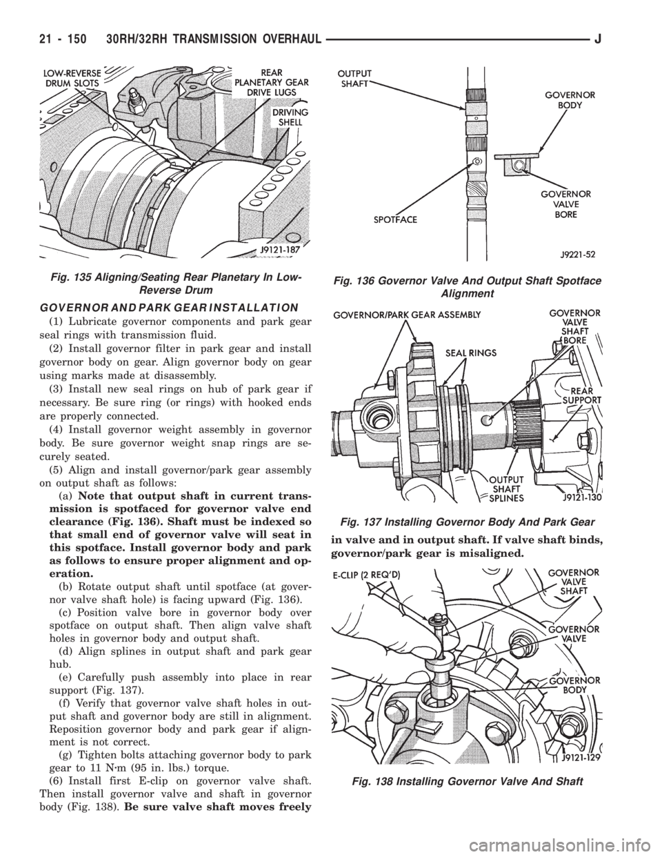
(a)Note that output shaft in current trans-
mission is spotfaced for governor valve end
clearance (Fig. 136). Shaft must be indexed so
that small end of governor valve will seat in
this spotface. Install governor body and park
as follows to ensure proper alignment and op-
eration.
(b) Rotate output shaft until spotface (at gover-
nor valve shaft hole) is facing upward (Fig. 136).
(c) Position valve bore in governor body over
spotface on output shaft. Then align valve shaft
holes in governor body and output shaft.
(d) Align splines in output shaft and park gear
hub.
(e) Carefully push assembly into place in rear
support (Fig. 137).
(f) Verify that governor valve shaft holes in out-
put shaft and governor body are still in alignment.
Reposition governor body and park gear if align-
ment is not correct.
(g) Tighten bolts attaching governor body to park
gear to 11 Nzm (95 in. lbs.) torque.
(6) Install first E-clip on governor valve shaft.
Then install governor valve and shaft in governor
body (Fig. 138).Be sure valve shaft moves freelyin valve and in output shaft. If valve shaft binds,
governor/park gear is misaligned.
Fig. 136 Governor Valve And Output Shaft Spotface
Alignment
Fig. 137 Installing Governor Body And Park Gear
Fig. 138 Installing Governor Valve And Shaft
Fig. 135 Aligning/Seating Rear Planetary In Low-
Reverse Drum
21 - 150 30RH/32RH TRANSMISSION OVERHAULJ
Page 1312 of 1784
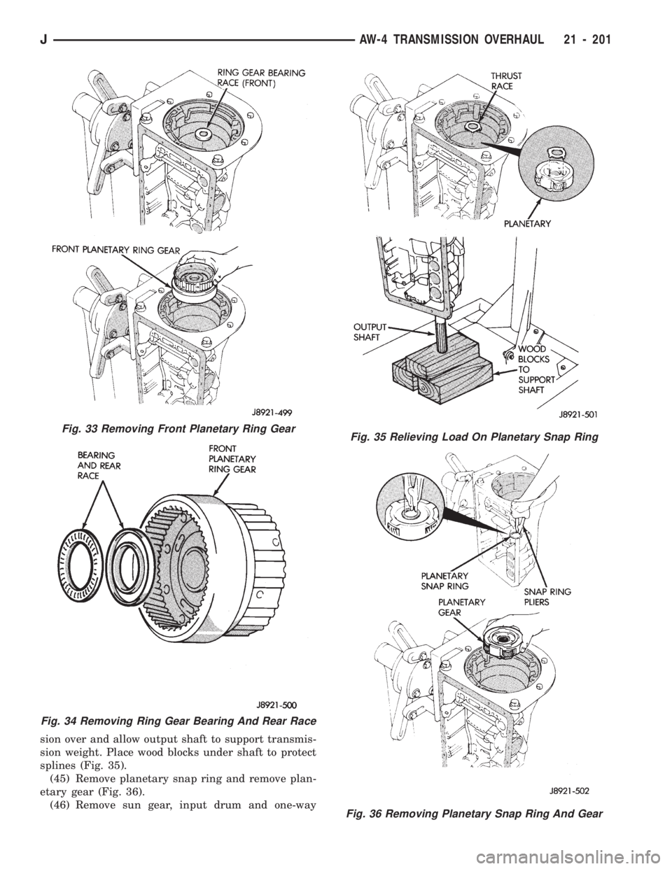
sion over and allow output shaft to support transmis-
sion weight. Place wood blocks under shaft to protect
splines (Fig. 35).
(45) Remove planetary snap ring and remove plan-
etary gear (Fig. 36).
(46) Remove sun gear, input drum and one-way
Fig. 33 Removing Front Planetary Ring Gear
Fig. 34 Removing Ring Gear Bearing And Rear Race
Fig. 35 Relieving Load On Planetary Snap Ring
Fig. 36 Removing Planetary Snap Ring And Gear
JAW-4 TRANSMISSION OVERHAUL 21 - 201
Page 1449 of 1784
WHEELS
GENERAL INFORMATION
Original equipment wheels are designed for the
specified Maximum Vehicle Capacity.
All models use steel or cast aluminum drop center
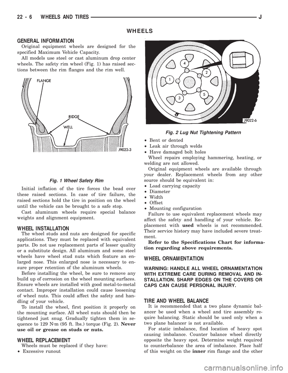
wheels. The safety rim wheel (Fig. 1) has raised sec-
tions between the rim flanges and the rim well.
Initial inflation of the tire forces the bead over
these raised sections. In case of tire failure, the
raised sections hold the tire in position on the wheel
until the vehicle can be brought to a safe stop.
Cast aluminum wheels require special balance
weights and alignment equipment.
WHEEL INSTALLATION
The wheel studs and nuts are designed for specific
applications. They must be replaced with equivalent
parts. Do not use replacement parts of lesser quality
or a substitute design. All aluminum and some steel
wheels have wheel stud nuts which feature an en-
larged nose. This enlarged nose is necessary to en-
sure proper retention of the aluminum wheels.
Before installing the wheel, be sure to remove any
build up of corrosion on the wheel mounting surfaces.
Ensure wheels are installed with good metal-to-metal
contact. Improper installation could cause loosening
of wheel nuts. This could affect the safety and han-
dling of your vehicle.
To install the wheel, first position it properly on
the mounting surface. All wheel nuts should then be
tightened just snug. Gradually tighten them in se-
quence to 129 Nzm (95 ft. lbs.) torque (Fig. 2).Never
use oil or grease on studs or nuts.
WHEEL REPLACEMENT
Wheels must be replaced if they have:
²Excessive runout²Bent or dented
²Leak air through welds
²Have damaged bolt holes
Wheel repairs employing hammering, heating, or
welding are not allowed.
Original equipment wheels are available through
your dealer. Replacement wheels from any other
source should be equivalent in:
²Load carrying capacity
²Diameter
²Width
²Offset
²Mounting configuration
Failure to use equivalent replacement wheels may
affect the safety and handling of your vehicle. Re-
placement withusedwheels is not recommended.
Their service history may have included severe treat-
ment.
Refer to the Specifications Chart for informa-
tion regarding above requirements.
WHEEL ORNAMENTATION
WARNING: HANDLE ALL WHEEL ORNAMENTATION
WITH EXTREME CARE DURING REMOVAL AND IN-
STALLATION. SHARP EDGES ON THE COVERS OR
CAPS CAN CAUSE PERSONAL INJURY.
TIRE AND WHEEL BALANCE
It is recommended that a two plane dynamic bal-
ancer be used when a wheel and tire assembly re-
quire balancing. Static should be used only when a
two plane balancer is not available.
For static imbalance, find location of heavy spot
causing imbalance. Counter balance wheel directly
opposite the heavy spot. Determine weight required
to counterbalance the area of imbalance. Place half
of this weight on theinnerrim flange and the other
Fig. 2 Lug Nut Tightening Pattern
Fig. 1 Wheel Safety Rim
22 - 6 WHEELS AND TIRESJ
Page 1543 of 1784
The reinforcement bracket is held on the
frame rail with two blind rivets.
(2) Remove the bracket and tow hook from frame
rail.
INSTALLATION
(1) Position bracket and tow hook on the frame
rail.
(2) Install bolts that attach tow hook bracket to
frame rail and reinforcement bracket. Tighten bolts
to 75 Nzm (55 ft-lbs) torque.
TRAILER HITCHES
CLASS III HITCHÐXJ VEHICLES
A class III weight-distributing/equalizer type hitch
can be used to tow a trailer:
²having a maximum gross weight of 5,000 lbs/2250
kg, and
²having a maximum tongue weight of 750 lbs/332
kg).
The following vehicle basic equipment is required
for class III trailer towing:
²P205/75R15 or larger tires;
²full size spare tire;
²trailer sway control;
²trailer tow wire harness and connector;
²heavy duty turn signal flasher element;
²heavy duty axle (with synthetic lubricant);²heavy duty cooling system;
²heavy duty generator/battery;
²auxiliary automatic transmission fluid cooler; and
²I-6, 4.0L engine.
Wide-angle type door mirrors are recommended but
not required.
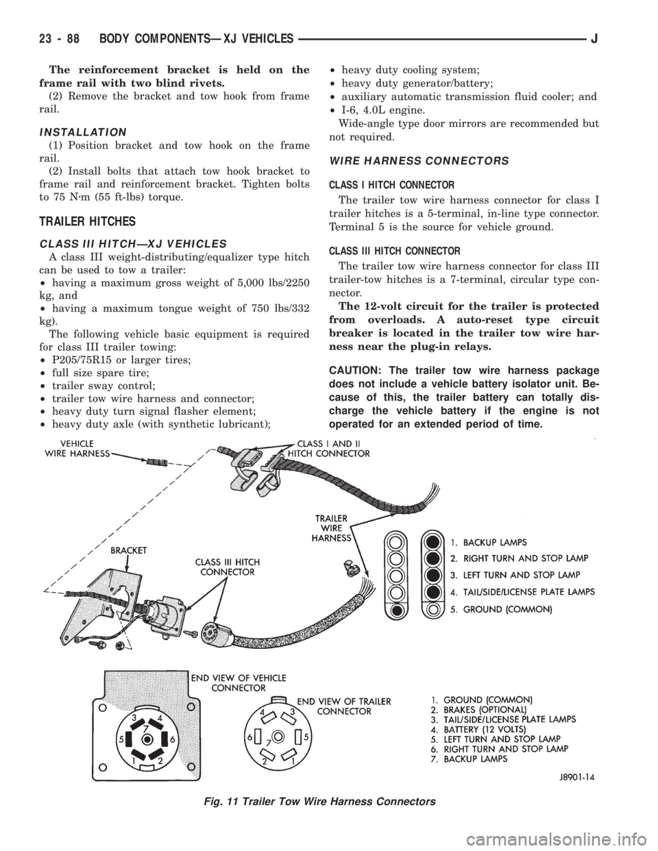
WIRE HARNESS CONNECTORS
CLASS I HITCH CONNECTOR
The trailer tow wire harness connector for class I
trailer hitches is a 5-terminal, in-line type connector.
Terminal 5 is the source for vehicle ground.
CLASS III HITCH CONNECTOR
The trailer tow wire harness connector for class III
trailer-tow hitches is a 7-terminal, circular type con-
nector.
The 12-volt circuit for the trailer is protected
from overloads. A auto-reset type circuit
breaker is located in the trailer tow wire har-
ness near the plug-in relays.
CAUTION: The trailer tow wire harness package
does not include a vehicle battery isolator unit. Be-
cause of this, the trailer battery can totally dis-
charge the vehicle battery if the engine is not
operated for an extended period of time.
Fig. 11 Trailer Tow Wire Harness Connectors
23 - 88 BODY COMPONENTSÐXJ VEHICLESJ
Page 1544 of 1784
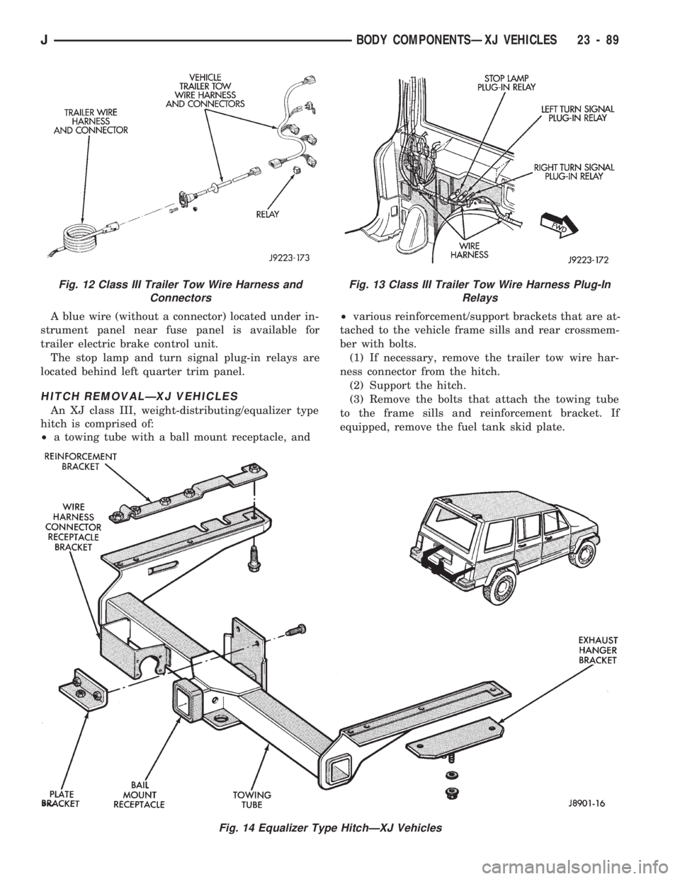
A blue wire (without a connector) located under in-
strument panel near fuse panel is available for
trailer electric brake control unit.
The stop lamp and turn signal plug-in relays are
located behind left quarter trim panel.
HITCH REMOVALÐXJ VEHICLES
An XJ class III, weight-distributing/equalizer type
hitch is comprised of:
²a towing tube with a ball mount receptacle, and²various reinforcement/support brackets that are at-
tached to the vehicle frame sills and rear crossmem-
ber with bolts.
(1) If necessary, remove the trailer tow wire har-
ness connector from the hitch.
(2) Support the hitch.
(3) Remove the bolts that attach the towing tube
to the frame sills and reinforcement bracket. If
equipped, remove the fuel tank skid plate.
Fig. 14 Equalizer Type HitchÐXJ Vehicles
Fig. 12 Class III Trailer Tow Wire Harness and
ConnectorsFig. 13 Class III Trailer Tow Wire Harness Plug-In
Relays
JBODY COMPONENTSÐXJ VEHICLES 23 - 89