1994 JEEP CHEROKEE Power steering
[x] Cancel search: Power steeringPage 245 of 1784
CAUTION: A number or letter is stamped into the
tongue of constant tension clamps. If replacement
is necessary, use only an original equipment clamp
with matching number or letter.
(12) Remove lower radiator hose from water pump.
Remove heater hose from water pump fitting.
(13) Remove four nuts or bolts (refer to the previ-
ous step #3).
(14) Remove the fan assembly and pulley (if fan is
installed at pump), or remove the pulley from the ve-
hicle.
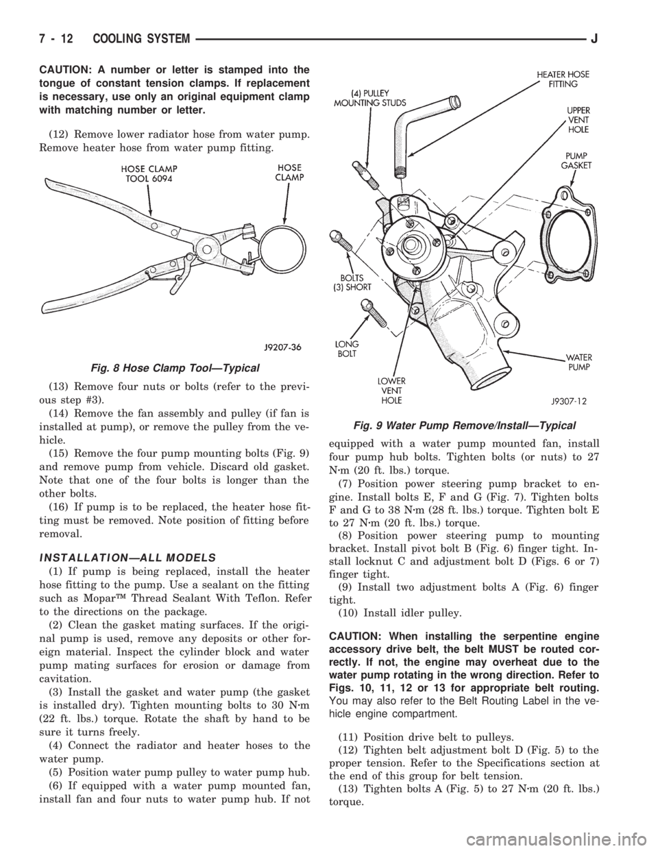
(15) Remove the four pump mounting bolts (Fig. 9)
and remove pump from vehicle. Discard old gasket.
Note that one of the four bolts is longer than the
other bolts.
(16) If pump is to be replaced, the heater hose fit-
ting must be removed. Note position of fitting before
removal.
INSTALLATIONÐALL MODELS
(1) If pump is being replaced, install the heater
hose fitting to the pump. Use a sealant on the fitting
such as MoparŸ Thread Sealant With Teflon. Refer
to the directions on the package.
(2) Clean the gasket mating surfaces. If the origi-
nal pump is used, remove any deposits or other for-
eign material. Inspect the cylinder block and water
pump mating surfaces for erosion or damage from
cavitation.
(3) Install the gasket and water pump (the gasket
is installed dry). Tighten mounting bolts to 30 Nzm
(22 ft. lbs.) torque. Rotate the shaft by hand to be
sure it turns freely.
(4) Connect the radiator and heater hoses to the
water pump.
(5) Position water pump pulley to water pump hub.
(6) If equipped with a water pump mounted fan,
install fan and four nuts to water pump hub. If notequipped with a water pump mounted fan, install
four pump hub bolts. Tighten bolts (or nuts) to 27
Nzm (20 ft. lbs.) torque.
(7) Position power steering pump bracket to en-
gine. Install bolts E, F and G (Fig. 7). Tighten bolts
FandGto38Nzm (28 ft. lbs.) torque. Tighten bolt E
to 27 Nzm (20 ft. lbs.) torque.
(8) Position power steering pump to mounting
bracket. Install pivot bolt B (Fig. 6) finger tight. In-
stall locknut C and adjustment bolt D (Figs. 6 or 7)
finger tight.
(9) Install two adjustment bolts A (Fig. 6) finger
tight.
(10) Install idler pulley.
CAUTION: When installing the serpentine engine
accessory drive belt, the belt MUST be routed cor-
rectly. If not, the engine may overheat due to the
water pump rotating in the wrong direction. Refer to
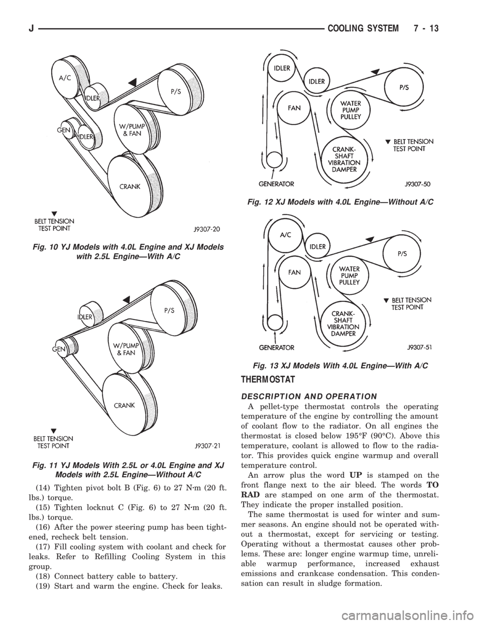
Figs. 10, 11, 12 or 13 for appropriate belt routing.
You may also refer to the Belt Routing Label in the ve-
hicle engine compartment.
(11) Position drive belt to pulleys.
(12) Tighten belt adjustment bolt D (Fig. 5) to the
proper tension. Refer to the Specifications section at
the end of this group for belt tension.
(13) Tighten bolts A (Fig. 5) to 27 Nzm (20 ft. lbs.)
torque.
Fig. 8 Hose Clamp ToolÐTypical
Fig. 9 Water Pump Remove/InstallÐTypical
7 - 12 COOLING SYSTEMJ
Page 246 of 1784
(14) Tighten pivot bolt B (Fig. 6) to 27 Nzm (20 ft.
lbs.) torque.
(15) Tighten locknut C (Fig. 6) to 27 Nzm (20 ft.
lbs.) torque.
(16) After the power steering pump has been tight-
ened, recheck belt tension.
(17) Fill cooling system with coolant and check for
leaks. Refer to Refilling Cooling System in this
group.
(18) Connect battery cable to battery.
(19) Start and warm the engine. Check for leaks.
THERMOSTAT
DESCRIPTION AND OPERATION
A pellet-type thermostat controls the operating
temperature of the engine by controlling the amount
of coolant flow to the radiator. On all engines the
thermostat is closed below 195ÉF (90ÉC). Above this
temperature, coolant is allowed to flow to the radia-
tor. This provides quick engine warmup and overall
temperature control.
An arrow plus the wordUPis stamped on the
front flange next to the air bleed. The wordsTO
RADare stamped on one arm of the thermostat.
They indicate the proper installed position.
The same thermostat is used for winter and sum-
mer seasons. An engine should not be operated with-
out a thermostat, except for servicing or testing.
Operating without a thermostat causes other prob-
lems. These are: longer engine warmup time, unreli-
able warmup performance, increased exhaust
emissions and crankcase condensation. This conden-
sation can result in sludge formation.
Fig. 10 YJ Models with 4.0L Engine and XJ Models
with 2.5L EngineÐWith A/C
Fig. 11 YJ Models With 2.5L or 4.0L Engine and XJ
Models with 2.5L EngineÐWithout A/C
Fig. 12 XJ Models with 4.0L EngineÐWithout A/C
Fig. 13 XJ Models With 4.0L EngineÐWith A/C
JCOOLING SYSTEM 7 - 13
Page 267 of 1784
BELT TENSIONÐRIGHT HAND DRIVE (RHD)
XJ MODELS WITH 4.0L ENGINE
It is not necessary to adjust belt tension on RHD
vehicles if equipped with a 4.0L engine. The engine
is equipped with an automatic belt tensioner (Fig. 7).
The tensioner maintains correct belt tension at all
times.Due to the use of this belt tensioner, DO
NOT attempt to use a belt tension gauge on this
engine.
BELT TENSION SPECIFICATIONS
Refer to the Specifications section at the end of this
group.
BELT SCHEMATICS
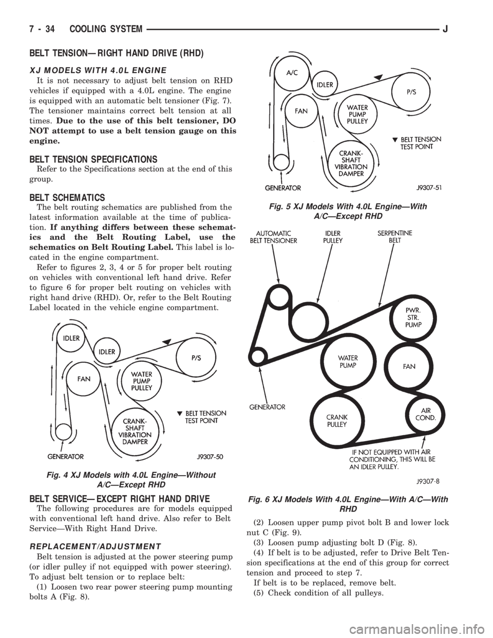
The belt routing schematics are published from the
latest information available at the time of publica-
tion.If anything differs between these schemat-
ics and the Belt Routing Label, use the
schematics on Belt Routing Label.This label is lo-
cated in the engine compartment.
Refer to figures 2, 3, 4 or 5 for proper belt routing
on vehicles with conventional left hand drive. Refer
to figure 6 for proper belt routing on vehicles with
right hand drive (RHD). Or, refer to the Belt Routing
Label located in the vehicle engine compartment.
BELT SERVICEÐEXCEPT RIGHT HAND DRIVE
The following procedures are for models equipped
with conventional left hand drive. Also refer to Belt
ServiceÐWith Right Hand Drive.
REPLACEMENT/ADJUSTMENT
Belt tension is adjusted at the power steering pump
(or idler pulley if not equipped with power steering).
To adjust belt tension or to replace belt:
(1) Loosen two rear power steering pump mounting
bolts A (Fig. 8).(2) Loosen upper pump pivot bolt B and lower lock
nut C (Fig. 9).
(3) Loosen pump adjusting bolt D (Fig. 8).
(4) If belt is to be adjusted, refer to Drive Belt Ten-
sion specifications at the end of this group for correct
tension and proceed to step 7.
If belt is to be replaced, remove belt.
(5) Check condition of all pulleys.
Fig. 4 XJ Models with 4.0L EngineÐWithout
A/CÐExcept RHD
Fig. 5 XJ Models With 4.0L EngineÐWith
A/CÐExcept RHD
Fig. 6 XJ Models With 4.0L EngineÐWith A/CÐWith
RHD
7 - 34 COOLING SYSTEMJ
Page 268 of 1784
CAUTION: When installing the serpentine accessory
drive belt, the belt MUST be routed correctly. If not,
the engine may overheat due to the water pump ro-
tating in the wrong direction. Refer to (Figs. 2, 3, 4
or 5) for correct belt routing.
(6) Install new belt. Refer to the end of this group
for Drive Belt Tension specifications.
(7) Tighten pump adjusting bolt D (Fig. 8) to at-
tain proper belt tension.(8) Tighten rear pump mounting bolts, pivot bolt
and lock nut to 27 Nzm (20 ft. lbs.) torque.
(9) After power steering pump has been tightened
into position, recheck belt tension. Adjust if neces-
sary.
BELT SERVICEÐWITH RIGHT HAND DRIVE
The following procedures are for XJ models
equipped with right hand drive (RHD) and a 4.0L en-
gine.
REMOVAL
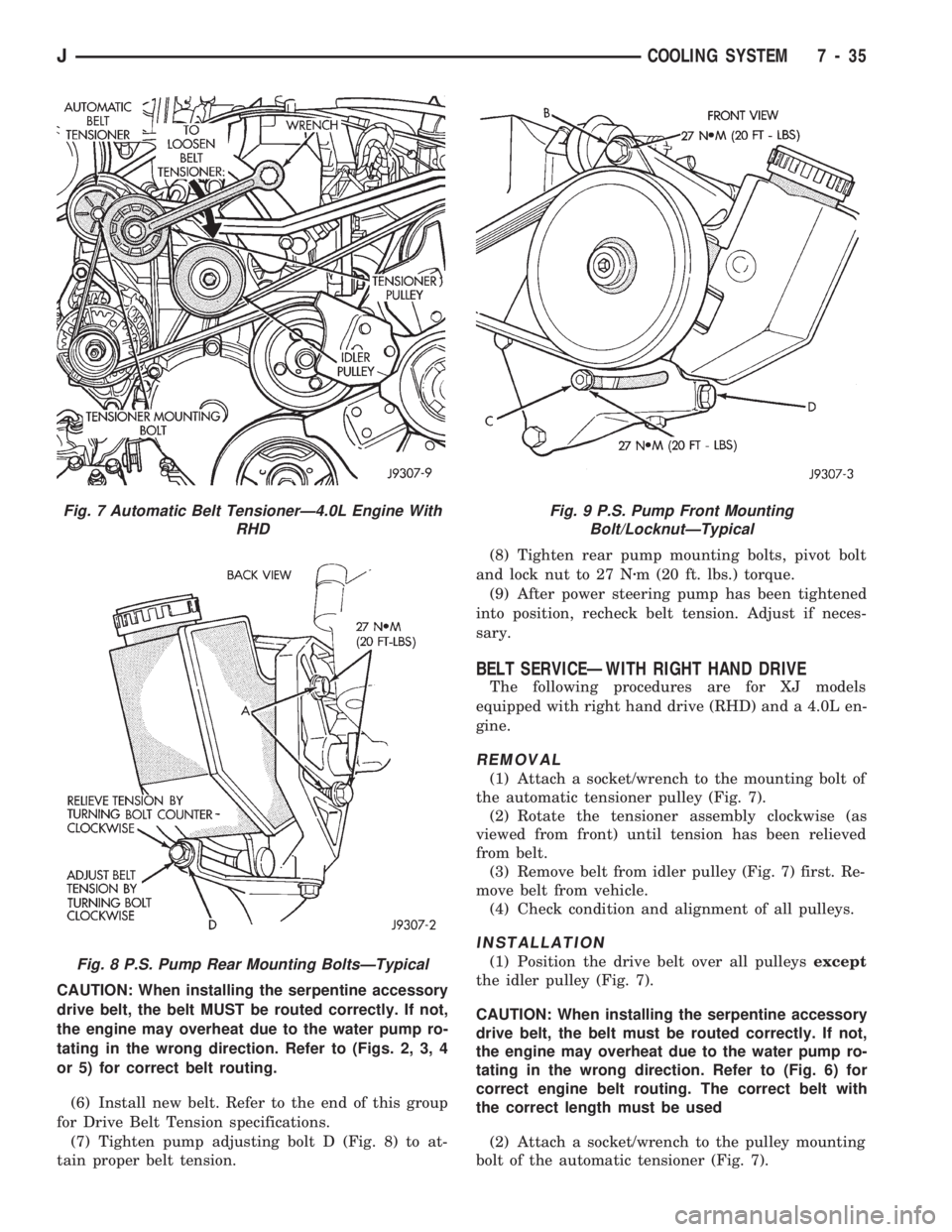
(1) Attach a socket/wrench to the mounting bolt of
the automatic tensioner pulley (Fig. 7).
(2) Rotate the tensioner assembly clockwise (as
viewed from front) until tension has been relieved
from belt.
(3) Remove belt from idler pulley (Fig. 7) first. Re-
move belt from vehicle.
(4) Check condition and alignment of all pulleys.
INSTALLATION
(1) Position the drive belt over all pulleysexcept
the idler pulley (Fig. 7).
CAUTION: When installing the serpentine accessory
drive belt, the belt must be routed correctly. If not,
the engine may overheat due to the water pump ro-
tating in the wrong direction. Refer to (Fig. 6) for
correct engine belt routing. The correct belt with
the correct length must be used
(2) Attach a socket/wrench to the pulley mounting
bolt of the automatic tensioner (Fig. 7).
Fig. 7 Automatic Belt TensionerÐ4.0L Engine With
RHD
Fig. 8 P.S. Pump Rear Mounting BoltsÐTypical
Fig. 9 P.S. Pump Front Mounting
Bolt/LocknutÐTypical
JCOOLING SYSTEM 7 - 35
Page 300 of 1784
GENERATOR SERVICE PROCEDURES
GENERAL
The generator is belt-driven by the engine. All en-
gines use serpentine drive. This section will cover
generator removal and installation. The generator is
not serviceable. Information covering on-vehicle test-
ing can be found in Group 8A - Battery/Starting/
Charging Systems Diagnostics.
GENERATOR REPLACEMENTÐLEFT HAND DRIVE
WARNING: FAILURE TO DISCONNECT NEGATIVE
CABLE FROM BATTERY BEFORE DISCONNECTING
RED (OUTPUT) WIRE CONNECTOR FROM GENER-
ATOR CAN RESULT IN INJURY.
ALL YJ AND XJ WITH 2.5L ENGINE
Belt tension is adjusted at the power steering pump
(or idler pulley if not equipped with power steering).
To replace generator:
(1) Disconnect negative cable from battery.
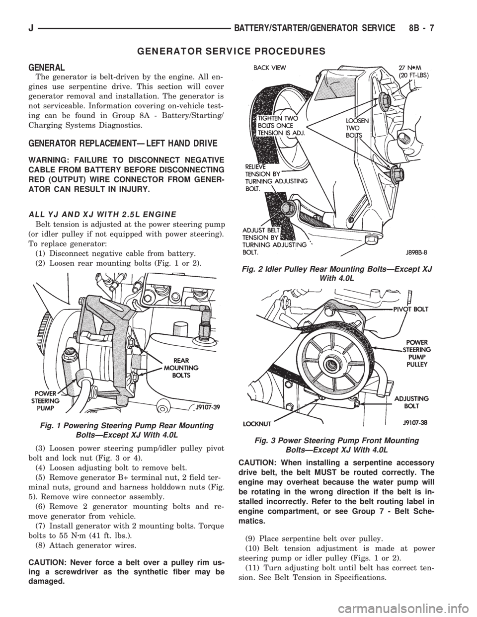
(2) Loosen rear mounting bolts (Fig. 1 or 2).
(3) Loosen power steering pump/idler pulley pivot
bolt and lock nut (Fig. 3 or 4).
(4) Loosen adjusting bolt to remove belt.
(5) Remove generator B+ terminal nut, 2 field ter-
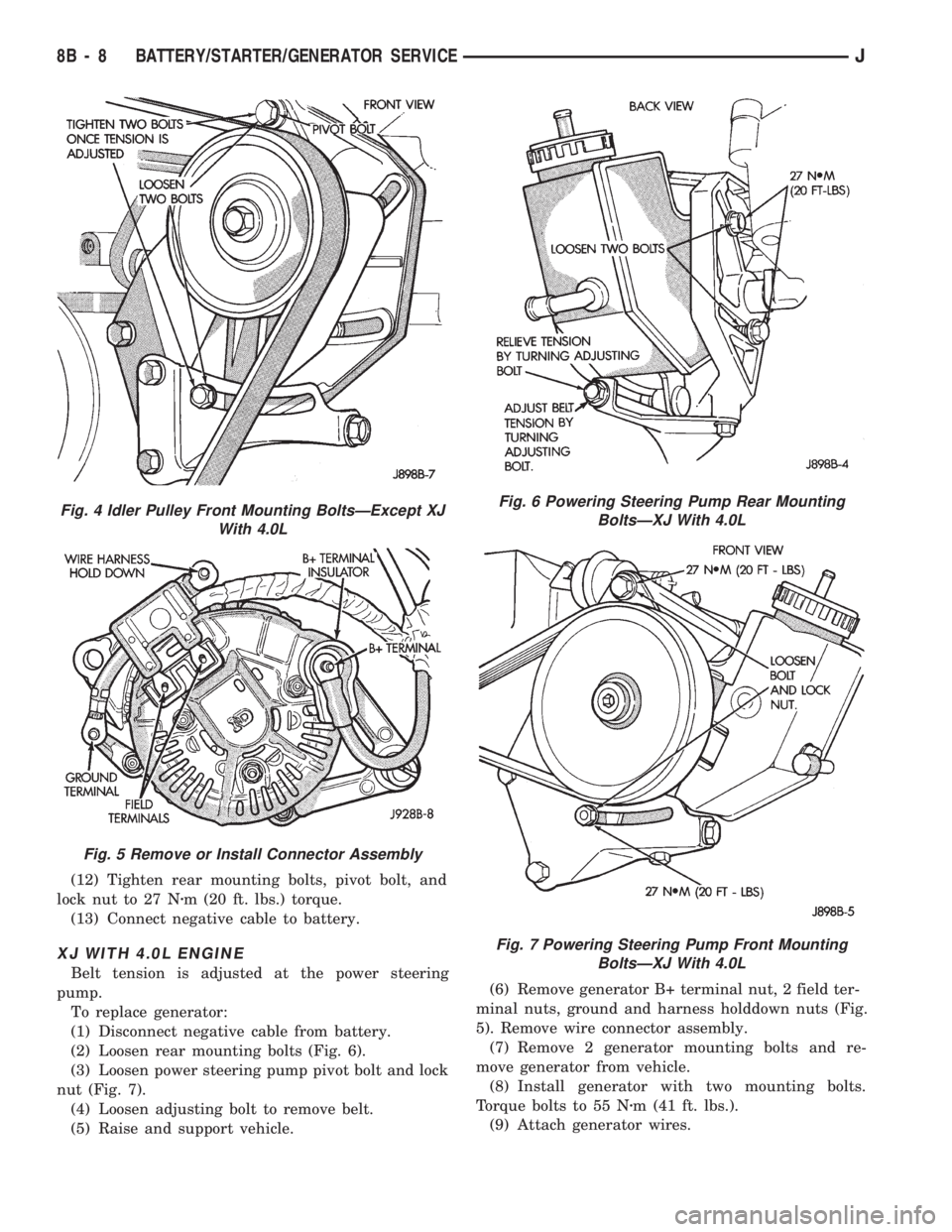
minal nuts, ground and harness holddown nuts (Fig.
5). Remove wire connector assembly.
(6) Remove 2 generator mounting bolts and re-
move generator from vehicle.
(7) Install generator with 2 mounting bolts. Torque
bolts to 55 Nzm (41 ft. lbs.).
(8) Attach generator wires.
CAUTION: Never force a belt over a pulley rim us-
ing a screwdriver as the synthetic fiber may be
damaged.CAUTION: When installing a serpentine accessory
drive belt, the belt MUST be routed correctly. The
engine may overheat because the water pump will
be rotating in the wrong direction if the belt is in-
stalled incorrectly. Refer to the belt routing label in
engine compartment, or see Group 7 - Belt Sche-
matics.
(9) Place serpentine belt over pulley.
(10) Belt tension adjustment is made at power
steering pump or idler pulley (Figs. 1 or 2).
(11) Turn adjusting bolt until belt has correct ten-
sion. See Belt Tension in Specifications.
Fig. 1 Powering Steering Pump Rear Mounting
BoltsÐExcept XJ With 4.0L
Fig. 2 Idler Pulley Rear Mounting BoltsÐExcept XJ
With 4.0L
Fig. 3 Power Steering Pump Front Mounting
BoltsÐExcept XJ With 4.0L
JBATTERY/STARTER/GENERATOR SERVICE 8B - 7
Page 301 of 1784
(12) Tighten rear mounting bolts, pivot bolt, and
lock nut to 27 Nzm (20 ft. lbs.) torque.
(13) Connect negative cable to battery.
XJ WITH 4.0L ENGINE
Belt tension is adjusted at the power steering
pump.
To replace generator:
(1) Disconnect negative cable from battery.
(2) Loosen rear mounting bolts (Fig. 6).
(3) Loosen power steering pump pivot bolt and lock
nut (Fig. 7).
(4) Loosen adjusting bolt to remove belt.
(5) Raise and support vehicle.(6) Remove generator B+ terminal nut, 2 field ter-
minal nuts, ground and harness holddown nuts (Fig.
5). Remove wire connector assembly.
(7) Remove 2 generator mounting bolts and re-
move generator from vehicle.
(8) Install generator with two mounting bolts.
Torque bolts to 55 Nzm (41 ft. lbs.).
(9) Attach generator wires.
Fig. 4 Idler Pulley Front Mounting BoltsÐExcept XJ
With 4.0L
Fig. 5 Remove or Install Connector Assembly
Fig. 6 Powering Steering Pump Rear Mounting
BoltsÐXJ With 4.0L
Fig. 7 Powering Steering Pump Front Mounting
BoltsÐXJ With 4.0L
8B - 8 BATTERY/STARTER/GENERATOR SERVICEJ
Page 302 of 1784
CAUTION: Never force a belt over a pulley rim us-
ing a screwdriver as the synthetic fiber may be
damaged.
CAUTION: When installing a serpentine accessory
drive belt, the belt MUST be routed correctly. The
engine may overheat because the water pump will
be rotating in the wrong direction if the belt is in-
stalled incorrectly. Refer to the belt routing label in
engine compartment, or see Group 7 - Belt Sche-
matics.
(10) Place serpentine belt over pulley.
(11) Belt tension adjustment is made at power
steering pump (Fig. 6).
(12) Turn adjusting bolt until belt has correct ten-
sion. See Belt Tension in Specifications.
(13) Tighten rear mounting bolts, pivot bolt, and
lock nut to 27 Nzm (20 ft. lbs.) torque.
(14) Remove support and lower vehicle.
(15) Connect negative cable to battery.
GENERATOR REPLACEMENTÐRIGHT HAND DRIVE
The generator used on the right hand drive is the
same as used on left hand drive. However, the
mounting and accessory drive belt installation are
different.
WARNING: FAILURE TO DISCONNECT NEGATIVE
CABLE FROM BATTERY BEFORE DISCONNECTING
RED (OUTPUT) WIRE CONNECTOR FROM GENER-
ATOR CAN RESULT IN INJURY.
(1) Remove negative cable from battery.
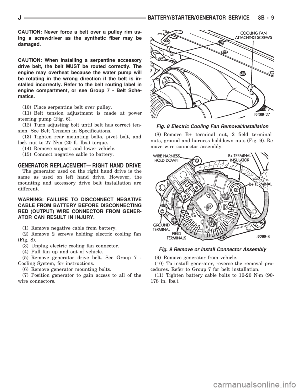
(2) Remove 2 screws holding electric cooling fan
(Fig. 8).
(3) Unplug electric cooling fan connector.
(4) Pull fan up and out of vehicle.
(5) Remove generator drive belt. See Group 7 -
Cooling System, for instructions.
(6) Remove generator mounting bolts.
(7) Position generator to gain access to all of the
wire connectors.(8) Remove B+ terminal nut, 2 field terminal
nuts, ground and harness holddown nuts (Fig. 9). Re-
move wire connector assembly.
(9) Remove generator from vehicle.
(10) To install generator, reverse the removal pro-
cedures. Refer to Group 7 for belt installation.
(11) Tighten battery cable bolts to 10-20 Nzm (90-
178 in. lbs.).
Fig. 8 Electric Cooling Fan Removal/Installation
Fig. 9 Remove or Install Connector Assembly
JBATTERY/STARTER/GENERATOR SERVICE 8B - 9
Page 361 of 1784

INSTRUMENT PANEL AND GAUGESÐYJE
CONTENTS
page page
GAUGE PACKAGE DIAGNOSIS............ 22
GAUGE PACKAGE GENERAL INFORMATION . 22
GAUGE PACKAGE SERVICE PROCEDURES . . 24
INSTRUMENT CLUSTER DIAGNOSIS....... 14INSTRUMENT CLUSTER GENERAL INFORMATION.14
INSTRUMENT CLUSTER SERVICE PROCEDURES.. 17
SPECIFICATIONS....................... 27
INSTRUMENT CLUSTER GENERAL INFORMATION
SPEEDOMETER/ODOMETER SYSTEM
The speedometer/odometer system consists of an
electric speedometer and pushbutton reset odometer
mounted in the cluster. The system also includes the
wire harness from the cluster to the vehicle speed
sensor at the transmission, and the adapter and pin-
ion in the transmission. A signal is sent from a
transmission mounted vehicle speed sensor to the
speedometer/odometer circuitry through the wiring
harness. Refer to Group 21 - Transmission for select-
ing the proper pinion, and selecting and indexing the
proper adapter.
TACHOMETER
The tachometer displays the engine speed (RPM).
With the engine running, the tachometer receives anengine speed signal from the Powertrain Control
Module pin 43 (values shown in Specifications chart).
INDICATOR LAMPS
The Brake, Upshift (2.5L with 5 speed transmis-
sion except California), and Malfunction Indicator
(Check Engine) lamps are located in the indicator
lamp panel above the steering column. The lamps
share a common battery feed connection through the
ignition switch and fuse #9.
The turn signals, high beam indicator, seat belt re-
minder, hazard lamp, master lighting and illumina-
tion bulbs are supplied battery voltage through
various switches and share a common ground.
INSTRUMENT CLUSTER DIAGNOSIS
INDEX
page page
Brake Indicator Lamp...................... 16
DiagnosingÐAll Lamps Out................. 16
Instrument Panel Illumination Lamps.......... 16
Malfunction Indicator Lamp (Check Engine)..... 16Seat Belt Reminder Lamp................... 16
Speedometer............................ 14
Tachometer............................. 14
Upshift Indicator Lamp..................... 16
SPEEDOMETER
(1) Raise vehicle.
(2) Disconnect the vehicle speed sensor connector.
(3) Connect a voltmeter between the black wire
pin of the connector and ground.
(4) Turn the ignition switch to the ON position.
(5) Check for approximately 5 volts. If OK, per-
form vehicle speed sensor test. Refer to the appropri-
ate Powertrain Diagnostic Procedures manual. If not
OK, continue with step 6.
(6) Turn ignition switch to OFF position.(7) Check continuity between vehicle speed sensor
connector and terminal 13 of instrument cluster con-
nector. If OK, replace speedometer. If not OK, repair
open circuit.
TACHOMETER
(1) Tachometer input is from the Powertrain Con-
trol Module (PCM) pin 43. Use the DRB scan tool to
perform actuator test. If OK, continue with step 2. If
not, replace PCM.
(2) Check for continuity between cluster connector
pin 12 and PCM pin 43. If OK, replace tachometer. If
not, repair open circuit.
8E - 14 YJ INSTRUMENT PANEL AND GAUGESJ