1994 JEEP CHEROKEE oil
[x] Cancel search: oilPage 1235 of 1784
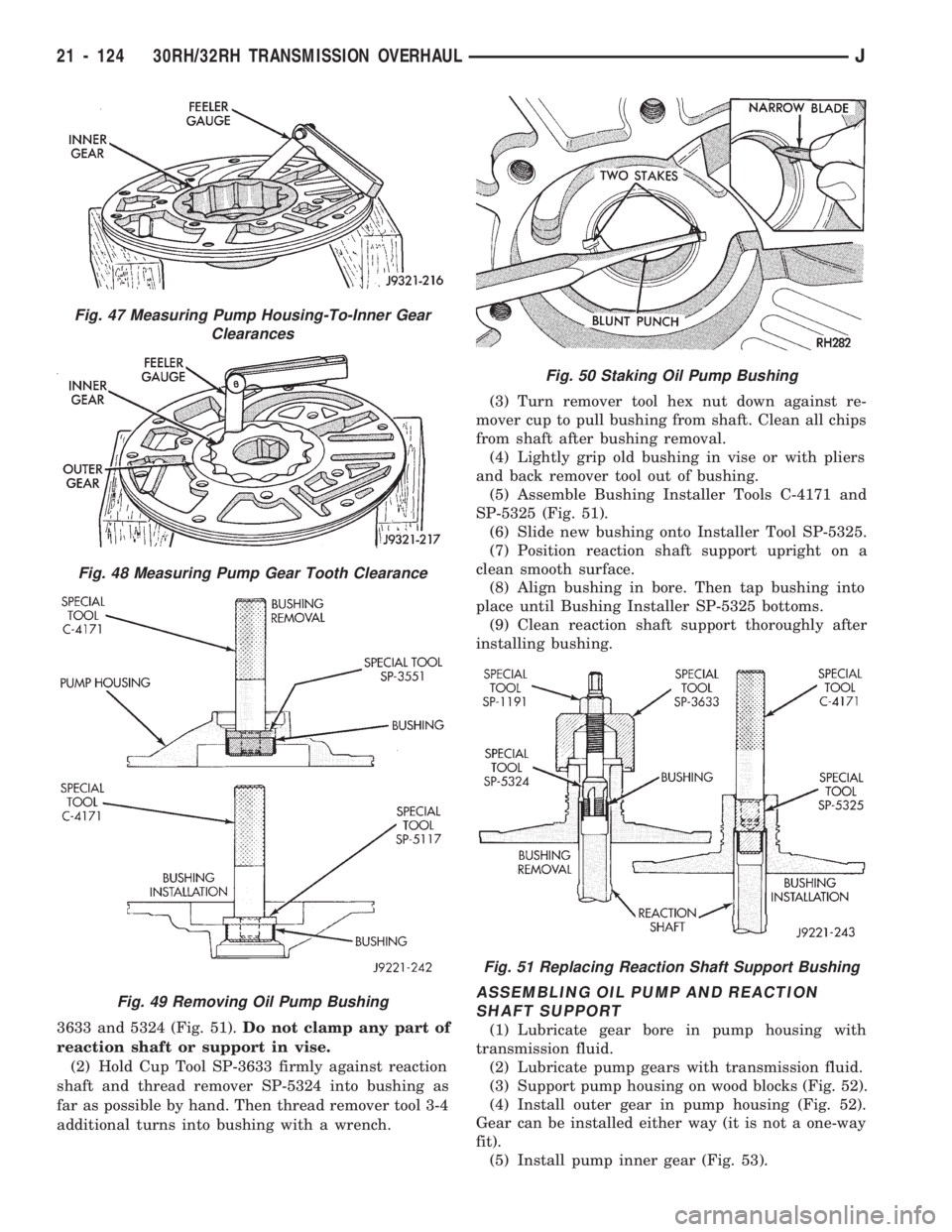
3633 and 5324 (Fig. 51).Do not clamp any part of
reaction shaft or support in vise.
(2) Hold Cup Tool SP-3633 firmly against reaction
shaft and thread remover SP-5324 into bushing as
far as possible by hand. Then thread remover tool 3-4
additional turns into bushing with a wrench.(3) Turn remover tool hex nut down against re-
mover cup to pull bushing from shaft. Clean all chips
from shaft after bushing removal.
(4) Lightly grip old bushing in vise or with pliers
and back remover tool out of bushing.
(5) Assemble Bushing Installer Tools C-4171 and
SP-5325 (Fig. 51).
(6) Slide new bushing onto Installer Tool SP-5325.
(7) Position reaction shaft support upright on a
clean smooth surface.
(8) Align bushing in bore. Then tap bushing into
place until Bushing Installer SP-5325 bottoms.
(9) Clean reaction shaft support thoroughly after
installing bushing.
ASSEMBLING OIL PUMP AND REACTION
SHAFT SUPPORT
(1) Lubricate gear bore in pump housing with
transmission fluid.
(2) Lubricate pump gears with transmission fluid.
(3) Support pump housing on wood blocks (Fig. 52).
(4) Install outer gear in pump housing (Fig. 52).
Gear can be installed either way (it is not a one-way
fit).
(5) Install pump inner gear (Fig. 53).
Fig. 47 Measuring Pump Housing-To-Inner Gear
Clearances
Fig. 48 Measuring Pump Gear Tooth Clearance
Fig. 49 Removing Oil Pump Bushing
Fig. 50 Staking Oil Pump Bushing
Fig. 51 Replacing Reaction Shaft Support Bushing
21 - 124 30RH/32RH TRANSMISSION OVERHAULJ
Page 1236 of 1784
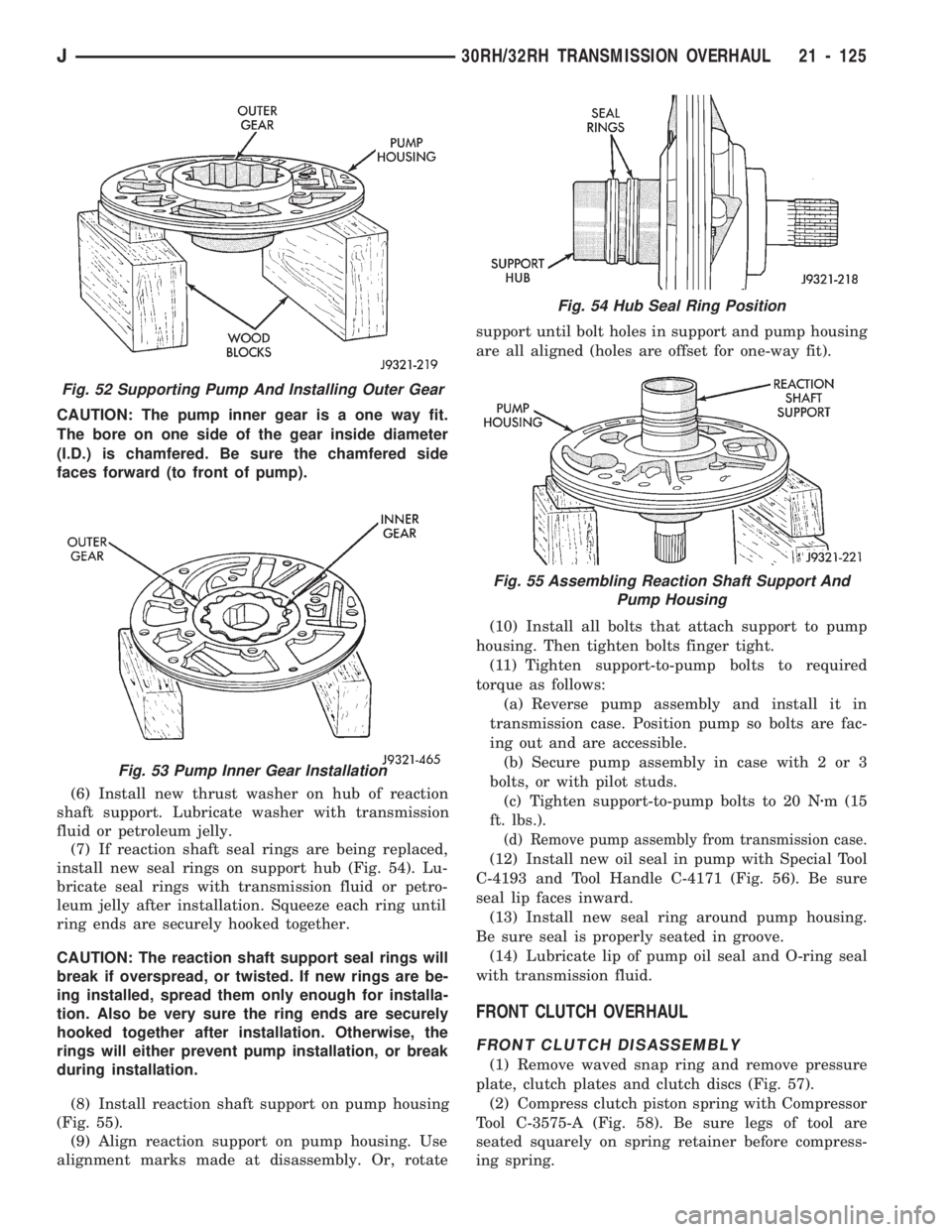
CAUTION: The pump inner gear is a one way fit.
The bore on one side of the gear inside diameter
(I.D.) is chamfered. Be sure the chamfered side
faces forward (to front of pump).
(6) Install new thrust washer on hub of reaction
shaft support. Lubricate washer with transmission
fluid or petroleum jelly.
(7) If reaction shaft seal rings are being replaced,
install new seal rings on support hub (Fig. 54). Lu-
bricate seal rings with transmission fluid or petro-
leum jelly after installation. Squeeze each ring until
ring ends are securely hooked together.
CAUTION: The reaction shaft support seal rings will
break if overspread, or twisted. If new rings are be-
ing installed, spread them only enough for installa-
tion. Also be very sure the ring ends are securely
hooked together after installation. Otherwise, the
rings will either prevent pump installation, or break
during installation.
(8) Install reaction shaft support on pump housing
(Fig. 55).
(9) Align reaction support on pump housing. Use
alignment marks made at disassembly. Or, rotatesupport until bolt holes in support and pump housing
are all aligned (holes are offset for one-way fit).
(10) Install all bolts that attach support to pump
housing. Then tighten bolts finger tight.
(11) Tighten support-to-pump bolts to required
torque as follows:
(a) Reverse pump assembly and install it in
transmission case. Position pump so bolts are fac-
ing out and are accessible.
(b) Secure pump assembly in case with 2 or 3
bolts, or with pilot studs.
(c) Tighten support-to-pump bolts to 20 Nzm (15
ft. lbs.).
(d) Remove pump assembly from transmission case.
(12) Install new oil seal in pump with Special Tool
C-4193 and Tool Handle C-4171 (Fig. 56). Be sure
seal lip faces inward.
(13) Install new seal ring around pump housing.
Be sure seal is properly seated in groove.
(14) Lubricate lip of pump oil seal and O-ring seal
with transmission fluid.
FRONT CLUTCH OVERHAUL
FRONT CLUTCH DISASSEMBLY
(1) Remove waved snap ring and remove pressure
plate, clutch plates and clutch discs (Fig. 57).
(2) Compress clutch piston spring with Compressor
Tool C-3575-A (Fig. 58). Be sure legs of tool are
seated squarely on spring retainer before compress-
ing spring.
Fig. 52 Supporting Pump And Installing Outer Gear
Fig. 53 Pump Inner Gear Installation
Fig. 54 Hub Seal Ring Position
Fig. 55 Assembling Reaction Shaft Support And
Pump Housing
J30RH/32RH TRANSMISSION OVERHAUL 21 - 125
Page 1237 of 1784
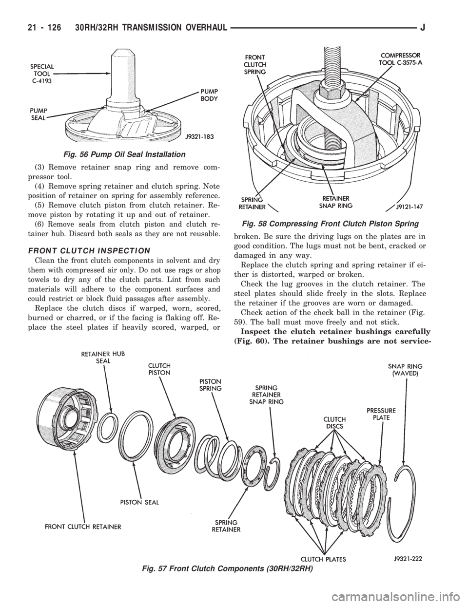
(3) Remove retainer snap ring and remove com-
pressor tool.
(4) Remove spring retainer and clutch spring. Note
position of retainer on spring for assembly reference.
(5) Remove clutch piston from clutch retainer. Re-
move piston by rotating it up and out of retainer.
(6) Remove seals from clutch piston and clutch re-
tainer hub. Discard both seals as they are not reusable.
FRONT CLUTCH INSPECTION
Clean the front clutch components in solvent and dry
them with compressed air only. Do not use rags or shop
towels to dry any of the clutch parts. Lint from such
materials will adhere to the component surfaces and
could restrict or block fluid passages after assembly.
Replace the clutch discs if warped, worn, scored,
burned or charred, or if the facing is flaking off. Re-
place the steel plates if heavily scored, warped, orbroken. Be sure the driving lugs on the plates are in
good condition. The lugs must not be bent, cracked or
damaged in any way.
Replace the clutch spring and spring retainer if ei-
ther is distorted, warped or broken.
Check the lug grooves in the clutch retainer. The
steel plates should slide freely in the slots. Replace
the retainer if the grooves are worn or damaged.
Check action of the check ball in the retainer (Fig.
59). The ball must move freely and not stick.
Inspect the clutch retainer bushings carefully
(Fig. 60). The retainer bushings are not service-
Fig. 56 Pump Oil Seal Installation
Fig. 57 Front Clutch Components (30RH/32RH)
Fig. 58 Compressing Front Clutch Piston Spring
21 - 126 30RH/32RH TRANSMISSION OVERHAULJ
Page 1253 of 1784
Inspect the valves and plugs for scratches, burrs,
nicks, or scores. Also inspect the coating on the alu-
minum valves and plugs (Fig. 114). If the coating is
damaged or worn through, the valve (or valve body)
should be replaced.
Aluminum valves and plugs should not be sanded
or polished under any circumstances. However, mi-
nor burrs or scratches on steel valves and plugs can
be removed with crocus cloth but do not round off the
valve or plug edges. Squareness of these edges is vi-
tally important. These edges prevent foreign matter
from lodging between the valves, plugs and bore.
Inspect all the valve and plug bores in the valve
body. Use a penlight to view the bore interiors. Re-place the valve body if any bores are distorted or
scored. Inspect all of the valve body springs. The
springs must be free of distortion, warpage or broken
coils.
Trial fit each valve and plug in its bore to check
freedom of operation. When clean and dry, the valves
and plugs should drop freely into the bores. Valve
body bores do not change dimensionally with use. If
the valve body functioned correctly when new, it will
continue to operate properly after cleaning and in-
spection. It should not be necessary to replace a
valve body assembly unless it is damaged in han-
dling.
21 - 142 30RH/32RH TRANSMISSION OVERHAULJ
Page 1263 of 1784
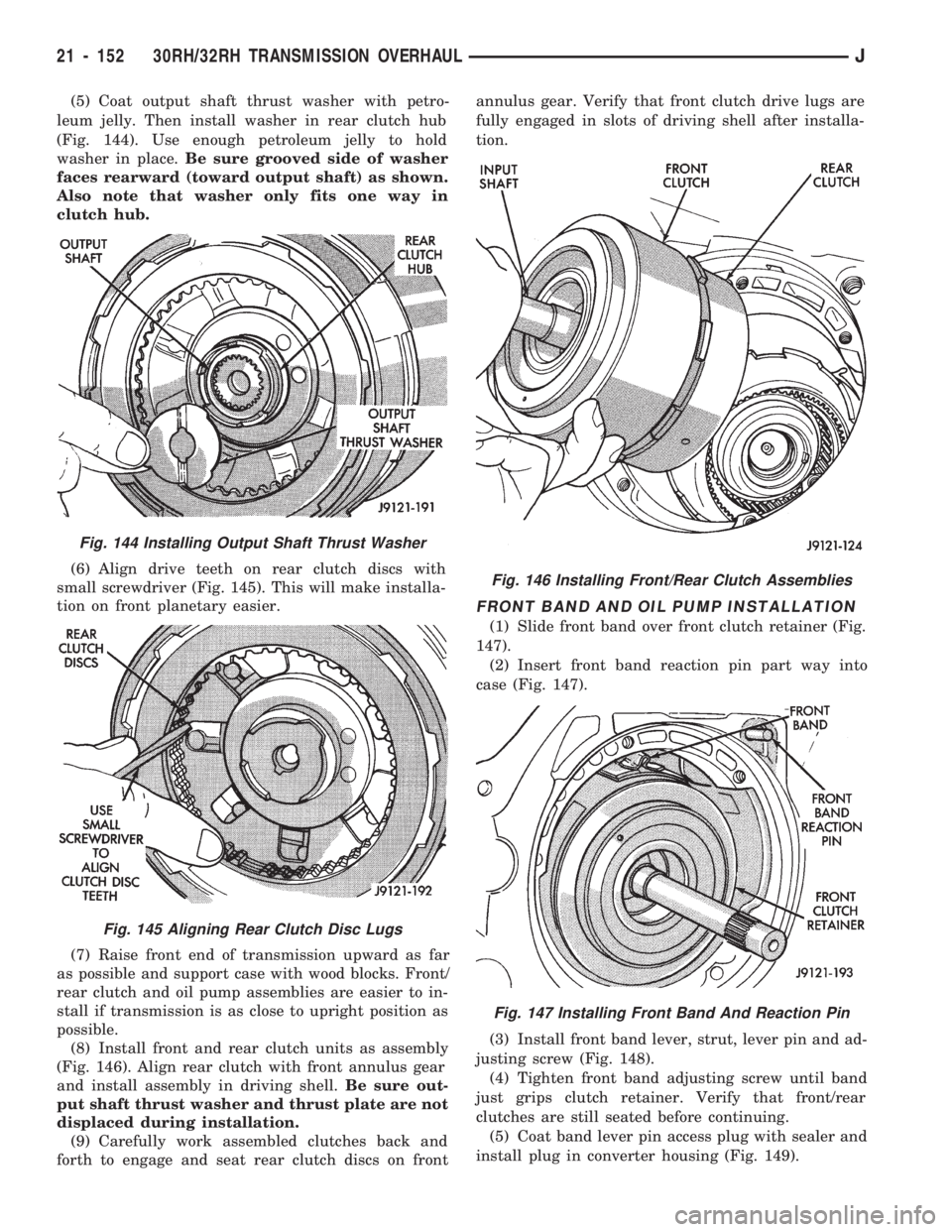
(5) Coat output shaft thrust washer with petro-
leum jelly. Then install washer in rear clutch hub
(Fig. 144). Use enough petroleum jelly to hold
washer in place.Be sure grooved side of washer
faces rearward (toward output shaft) as shown.
Also note that washer only fits one way in
clutch hub.
(6) Align drive teeth on rear clutch discs with
small screwdriver (Fig. 145). This will make installa-
tion on front planetary easier.
(7) Raise front end of transmission upward as far
as possible and support case with wood blocks. Front/
rear clutch and oil pump assemblies are easier to in-
stall if transmission is as close to upright position as
possible.
(8) Install front and rear clutch units as assembly
(Fig. 146). Align rear clutch with front annulus gear
and install assembly in driving shell.Be sure out-
put shaft thrust washer and thrust plate are not
displaced during installation.
(9) Carefully work assembled clutches back and
forth to engage and seat rear clutch discs on frontannulus gear. Verify that front clutch drive lugs are
fully engaged in slots of driving shell after installa-
tion.
FRONT BAND AND OIL PUMP INSTALLATION
(1) Slide front band over front clutch retainer (Fig.
147).
(2) Insert front band reaction pin part way into
case (Fig. 147).
(3) Install front band lever, strut, lever pin and ad-
justing screw (Fig. 148).
(4) Tighten front band adjusting screw until band
just grips clutch retainer. Verify that front/rear
clutches are still seated before continuing.
(5) Coat band lever pin access plug with sealer and
install plug in converter housing (Fig. 149).
Fig. 144 Installing Output Shaft Thrust Washer
Fig. 145 Aligning Rear Clutch Disc Lugs
Fig. 146 Installing Front/Rear Clutch Assemblies
Fig. 147 Installing Front Band And Reaction Pin
21 - 152 30RH/32RH TRANSMISSION OVERHAULJ
Page 1264 of 1784
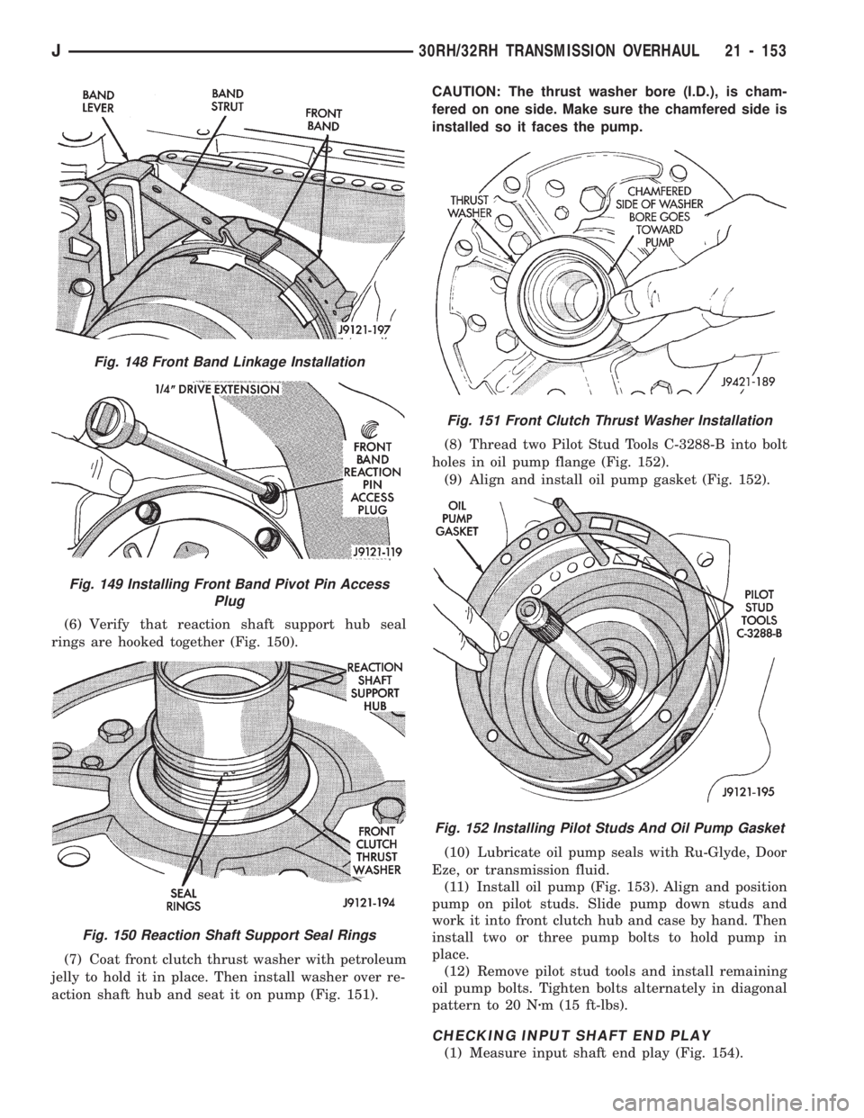
(6) Verify that reaction shaft support hub seal
rings are hooked together (Fig. 150).
(7) Coat front clutch thrust washer with petroleum
jelly to hold it in place. Then install washer over re-
action shaft hub and seat it on pump (Fig. 151).CAUTION: The thrust washer bore (I.D.), is cham-
fered on one side. Make sure the chamfered side is
installed so it faces the pump.
(8) Thread two Pilot Stud Tools C-3288-B into bolt
holes in oil pump flange (Fig. 152).
(9) Align and install oil pump gasket (Fig. 152).
(10) Lubricate oil pump seals with Ru-Glyde, Door
Eze, or transmission fluid.
(11) Install oil pump (Fig. 153). Align and position
pump on pilot studs. Slide pump down studs and
work it into front clutch hub and case by hand. Then
install two or three pump bolts to hold pump in
place.
(12) Remove pilot stud tools and install remaining
oil pump bolts. Tighten bolts alternately in diagonal
pattern to 20 Nzm (15 ft-lbs).
CHECKING INPUT SHAFT END PLAY
(1) Measure input shaft end play (Fig. 154).
Fig. 148 Front Band Linkage Installation
Fig. 149 Installing Front Band Pivot Pin Access
Plug
Fig. 150 Reaction Shaft Support Seal Rings
Fig. 151 Front Clutch Thrust Washer Installation
Fig. 152 Installing Pilot Studs And Oil Pump Gasket
J30RH/32RH TRANSMISSION OVERHAUL 21 - 153
Page 1265 of 1784
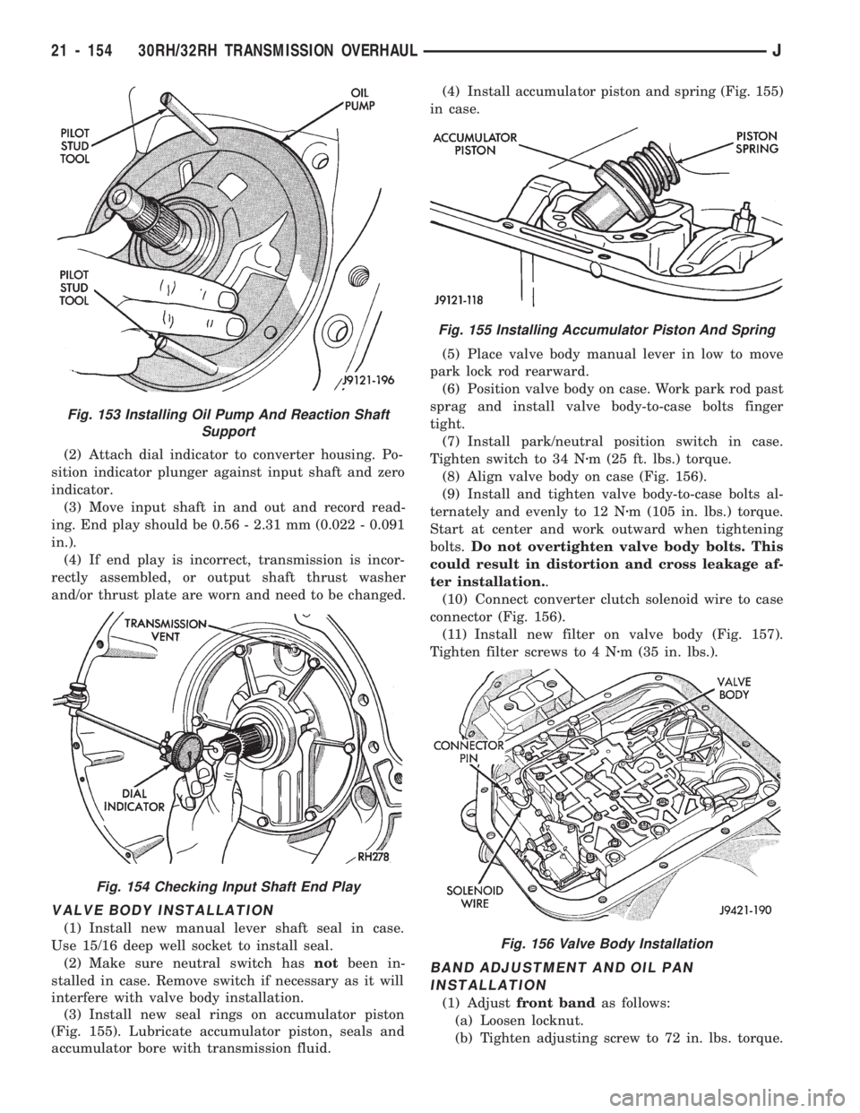
(2) Attach dial indicator to converter housing. Po-
sition indicator plunger against input shaft and zero
indicator.
(3) Move input shaft in and out and record read-
ing. End play should be 0.56 - 2.31 mm (0.022 - 0.091
in.).
(4) If end play is incorrect, transmission is incor-
rectly assembled, or output shaft thrust washer
and/or thrust plate are worn and need to be changed.
VALVE BODY INSTALLATION
(1) Install new manual lever shaft seal in case.
Use 15/16 deep well socket to install seal.
(2) Make sure neutral switch hasnotbeen in-
stalled in case. Remove switch if necessary as it will
interfere with valve body installation.
(3) Install new seal rings on accumulator piston
(Fig. 155). Lubricate accumulator piston, seals and
accumulator bore with transmission fluid.(4) Install accumulator piston and spring (Fig. 155)
in case.
(5) Place valve body manual lever in low to move
park lock rod rearward.
(6) Position valve body on case. Work park rod past
sprag and install valve body-to-case bolts finger
tight.
(7) Install park/neutral position switch in case.
Tighten switch to 34 Nzm (25 ft. lbs.) torque.
(8) Align valve body on case (Fig. 156).
(9) Install and tighten valve body-to-case bolts al-
ternately and evenly to 12 Nzm (105 in. lbs.) torque.
Start at center and work outward when tightening
bolts.Do not overtighten valve body bolts. This
could result in distortion and cross leakage af-
ter installation..
(10) Connect converter clutch solenoid wire to case
connector (Fig. 156).
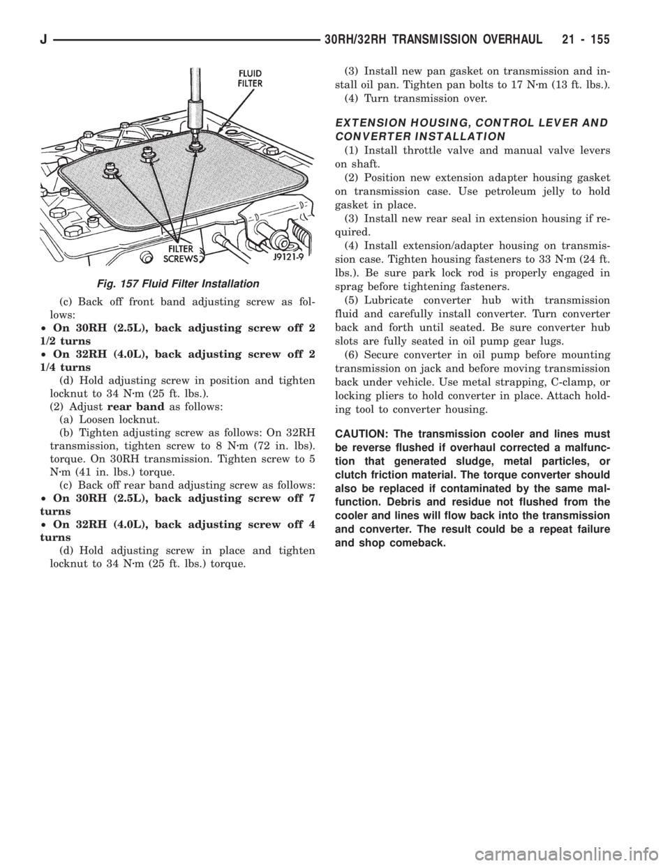
(11) Install new filter on valve body (Fig. 157).
Tighten filter screws to 4 Nzm (35 in. lbs.).
BAND ADJUSTMENT AND OIL PAN
INSTALLATION
(1) Adjustfront bandas follows:
(a) Loosen locknut.
(b) Tighten adjusting screw to 72 in. lbs. torque.
Fig. 153 Installing Oil Pump And Reaction Shaft
Support
Fig. 154 Checking Input Shaft End Play
Fig. 155 Installing Accumulator Piston And Spring
Fig. 156 Valve Body Installation
21 - 154 30RH/32RH TRANSMISSION OVERHAULJ
Page 1266 of 1784
(c) Back off front band adjusting screw as fol-
lows:
²On 30RH (2.5L), back adjusting screw off 2
1/2 turns
²On 32RH (4.0L), back adjusting screw off 2
1/4 turns
(d) Hold adjusting screw in position and tighten
locknut to 34 Nzm (25 ft. lbs.).
(2) Adjustrear bandas follows:
(a) Loosen locknut.
(b) Tighten adjusting screw as follows: On 32RH
transmission, tighten screw to 8 Nzm (72 in. lbs).
torque. On 30RH transmission. Tighten screw to 5
Nzm (41 in. lbs.) torque.
(c) Back off rear band adjusting screw as follows:
²On 30RH (2.5L), back adjusting screw off 7
turns
²On 32RH (4.0L), back adjusting screw off 4
turns
(d) Hold adjusting screw in place and tighten
locknut to 34 Nzm (25 ft. lbs.) torque.(3) Install new pan gasket on transmission and in-
stall oil pan. Tighten pan bolts to 17 Nzm (13 ft. lbs.).
(4) Turn transmission over.
EXTENSION HOUSING, CONTROL LEVER AND
CONVERTER INSTALLATION
(1) Install throttle valve and manual valve levers
on shaft.
(2) Position new extension adapter housing gasket
on transmission case. Use petroleum jelly to hold
gasket in place.
(3) Install new rear seal in extension housing if re-
quired.
(4) Install extension/adapter housing on transmis-
sion case. Tighten housing fasteners to 33 Nzm (24 ft.
lbs.). Be sure park lock rod is properly engaged in
sprag before tightening fasteners.
(5) Lubricate converter hub with transmission
fluid and carefully install converter. Turn converter
back and forth until seated. Be sure converter hub
slots are fully seated in oil pump gear lugs.
(6) Secure converter in oil pump before mounting
transmission on jack and before moving transmission
back under vehicle. Use metal strapping, C-clamp, or
locking pliers to hold converter in place. Attach hold-
ing tool to converter housing.
CAUTION: The transmission cooler and lines must
be reverse flushed if overhaul corrected a malfunc-
tion that generated sludge, metal particles, or
clutch friction material. The torque converter should
also be replaced if contaminated by the same mal-
function. Debris and residue not flushed from the
cooler and lines will flow back into the transmission
and converter. The result could be a repeat failure
and shop comeback.
Fig. 157 Fluid Filter Installation
J30RH/32RH TRANSMISSION OVERHAUL 21 - 155