1994 JEEP CHEROKEE oil
[x] Cancel search: oilPage 1054 of 1784
STEERING LINKAGEÐYJ
INDEX
page page
Drag Link.............................. 17
Pitman Arm............................. 18
Service Information....................... 17Steering Dampener....................... 18
Tie Rod ................................ 17
SERVICE INFORMATION
The steering linkage consists of a pitman arm, drag
link, tie rod, and steering dampener. Adjustment
sleeves are used on the tie rod and drag link for toe
and steering wheel alignment.
Refer to Group 2, Front Suspension and Axle for
additional information.
The tie-rod end ball stud seals should be inspected
during all oil changes.
A damaged ball stud seal requires removal of the
seal. Inspect the tie-rod end ball stud at the throat
opening. Check for lubricant loss, contamination, ball
stud wear or corrosion. If these conditions exist, re-
place the tie-rod. A replacement seal can be installed
if lubricant is in good condition. Otherwise, a com-
plete replacement ball stud end should be installed.
Lubricate the tie-rod end with MOPARtMulti-Mile-
age Lubricant, or equivalent product.
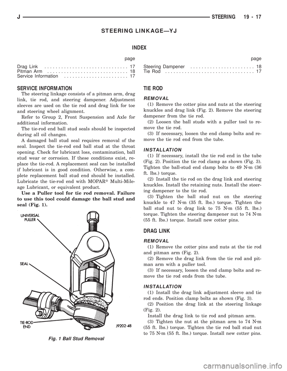
Use a Puller tool for tie rod removal. Failure
to use this tool could damage the ball stud and
seal (Fig. 1).
TIE ROD
REMOVAL
(1) Remove the cotter pins and nuts at the steering
knuckles and drag link (Fig. 2). Remove the steering
dampener from the tie rod.
(2) Loosen the ball studs with a puller tool to re-
move the tie rod.
(3) If necessary, loosen the end clamp bolts and re-
move the tie rod end from the tube.
INSTALLATION
(1) If necessary, install the tie rod end in the tube
(Fig. 2). Position the tie rod clamp as shown (Fig. 3).
Tighten the ball-stud end clamp bolts to 49 Nzm (36
ft. lbs.) torque.
(2) Install the tie rod on the drag link and steering
knuckles. Install the retaining nuts. Install the steer-
ing dampener to the tie rod.
(3) Tighten the ball stud nut on the steering
knuckle to 47 Nzm (35 ft. lbs.) torque. Tighten the
ball stud nut to drag link to 75 Nzm (55 ft. lbs.)
torque. Tighten the steering dampener nut to 74 Nzm
(55 ft. lbs.) torque. Install new cotter pins.
DRAG LINK
REMOVAL
(1) Remove the cotter pins and nuts at the tie rod
and pitman arm (Fig. 2).
(2) Remove the drag link from the tie rod and pit-
man arm with a puller tool.
(3) If necessary, loosen the end clamp bolts and re-
move the tie rod ends from the tube.
INSTALLATION
(1) Install the drag link adjustment sleeve and tie
rod ends. Position clamp bolts as shown (Fig. 3).
(2) Position the drag link at the steering linkage
(Fig. 2).
Install the drag link to tie rod and pitman arm.
(3) Tighten the nut at the pitman arm to 74 Nzm
(55 ft. lbs.) torque. Tighten the tie rod ball stud nut
to 75 Nzm (55 ft. lbs.) torque. Install new cotter pins.
Fig. 1 Ball Stud Removal
JSTEERING 19 - 17
Page 1113 of 1784
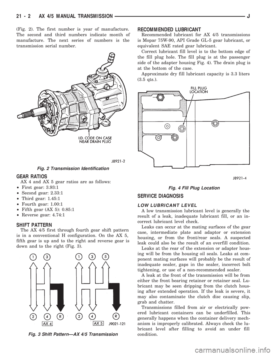
(Fig. 2). The first number is year of manufacture.
The second and third numbers indicate month of
manufacture. The next series of numbers is the
transmission serial number.
GEAR RATIOS
AX 4 and AX 5 gear ratios are as follows:
²First gear: 3.93:1
²Second gear: 2.33:1
²Third gear: 1.45:1
²Fourth gear: 1.00:1
²Fifth gear (AX 5): 0.85:1
²Reverse gear: 4.74:1
SHIFT PATTERN
The AX 4/5 first through fourth gear shift pattern
is in a conventional H configuration. On the AX 5,
fifth gear is up and to the right and reverse gear is
down and to the right (Fig. 3).
RECOMMENDED LUBRICANT
Recommended lubricant for AX 4/5 transmissions
is Mopar 75W-90, API Grade GL-5 gear lubricant, or
equivalent SAE rated gear lubricant.
Correct lubricant fill level is to the bottom edge of
the fill plug hole. The fill plug is at the passenger
side of the adapter housing Fig. 4). The drain plug is
at the bottom of the case.
Approximate dry fill lubricant capacity is 3.3 liters
(3.5 qts.).
SERVICE DIAGNOSIS
LOW LUBRICANT LEVEL
A low transmission lubricant level is generally the
result of a leak, inadequate lubricant fill, or an in-
correct lubricant level check.
Leaks can occur at the mating surfaces of the gear
case, intermediate plate and adaptor or extension
housing, or from the front/rear seals. A suspected
leak could also be the result of an overfill condition.
Leaks at the rear of the extension or adapter hous-
ing will be from the housing oil seals. Leaks at com-
ponent mating surfaces will probably be the result of
inadequate sealer, gaps in the sealer, incorrect bolt
tightening, or use of a non-recommended sealer.
A leak at the front of the transmission will be from
either the front bearing retainer or retainer seal. Lu-
bricant may be seen dripping from the clutch hous-
ing after extended operation. If the leak is severe, it
may also contaminate the clutch disc causing slip,
grab and chatter.
Transmissions filled from air or electrically pow-
ered lubricant containers can be underfilled. This
generally happens when the container delivery mech-
anism is improperly calibrated. Always check the lu-
bricant level after filling to avoid an under fill
condition.
Fig. 2 Transmission Identification
Fig. 3 Shift PatternÐAX 4/5 Transmission
Fig. 4 Fill Plug Location
21 - 2 AX 4/5 MANUAL TRANSMISSIONJ
Page 1114 of 1784
A correct lubricant level check can only be made
when the vehicle is level; use a drive-on hoist to en-
sure this. Also allow the lubricant to settle for a
minute or so before checking. These recommenda-
tions will ensure an accurate check and avoid an un-
der-or-overfill condition.
HARD SHIFTING
Hard shifting is usually caused by a low lubricant
level, improper or contaminated lubricants, compo-
nent damage, incorrect clutch adjustment, or by a
damaged clutch pressure plate or disc.
Substantial lubricant leaks can result in gear, shift
rail, synchro and bearing damage. If a leak goes un-
detected for an extended period, the first indications
of a problem are usually hard shifting and noise.
Incorrect or contaminated lubricants can also con-
tribute to hard shifting. The consequence of using
non-recommended lubricants is noise, excessive wear,
internal bind and hard shifting.
Improper clutch release is a frequent cause of hard
shifting. Incorrect adjustment or a worn, damaged
pressure plate or disc can cause incorrect release. If
the clutch problem is advanced, gear clash during
shifts can result.
Worn or damaged synchro rings can cause gear
clash when shifting into any forward gear. In some
new or rebuilt transmissions, new synchro rings maytend to stick slightly causing hard or noisy shifts. In
most cases, this condition will decline as the rings
wear-in.
TRANSMISSION NOISE
Most manual transmissions make some noise dur-
ing normal operation. Rotating gears can generate a
mild whine that may only be audible at extreme
speeds.
Severe, obviously audible transmission noise is
generally the result of a lubricant problem. Insuffi-
cient, improper, or contaminated lubricant can pro-
mote rapid wear of gears, synchros, shift rails, forks
and bearings. The overheating caused by a lubricant
problem, can also lead to gear breakage.
TRANSMISSION REMOVAL
(1) Shift transmission into first or third gear. Then
raise vehicle on hoist.
(2) Support engine with adjustable jack stand. Be
sure to position wood block between jack and oil pan.
(3) Disconnect necessary exhaust system compo-
nents.
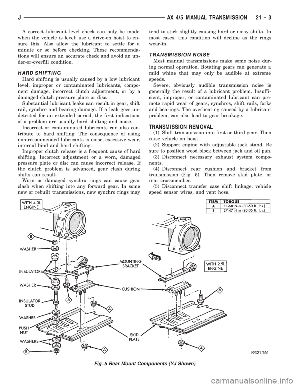
(4) Disconnect rear cushion and bracket from
transmission (Fig. 5). Then remove skid plate, or
rear crossmember.
(5) Disconnect transfer case shift linkage, vehicle
speed sensor wires, and vent hose.
Fig. 5 Rear Mount Components (YJ Shown)
JAX 4/5 MANUAL TRANSMISSION 21 - 3
Page 1121 of 1784
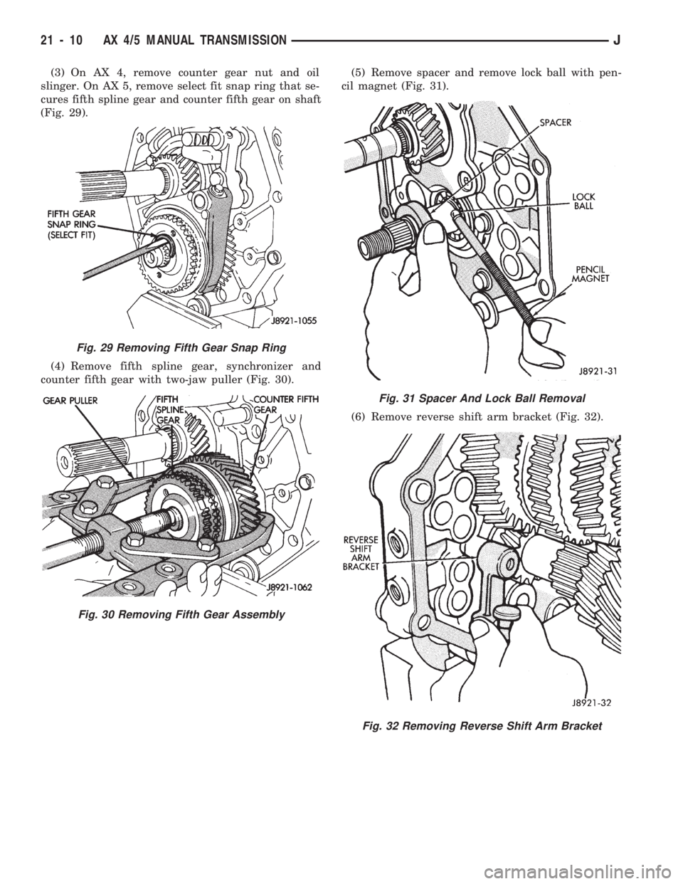
(3) On AX 4, remove counter gear nut and oil
slinger. On AX 5, remove select fit snap ring that se-
cures fifth spline gear and counter fifth gear on shaft
(Fig. 29).
(4) Remove fifth spline gear, synchronizer and
counter fifth gear with two-jaw puller (Fig. 30).(5) Remove spacer and remove lock ball with pen-
cil magnet (Fig. 31).
(6) Remove reverse shift arm bracket (Fig. 32).
Fig. 29 Removing Fifth Gear Snap Ring
Fig. 30 Removing Fifth Gear Assembly
Fig. 31 Spacer And Lock Ball Removal
Fig. 32 Removing Reverse Shift Arm Bracket
21 - 10 AX 4/5 MANUAL TRANSMISSIONJ
Page 1125 of 1784
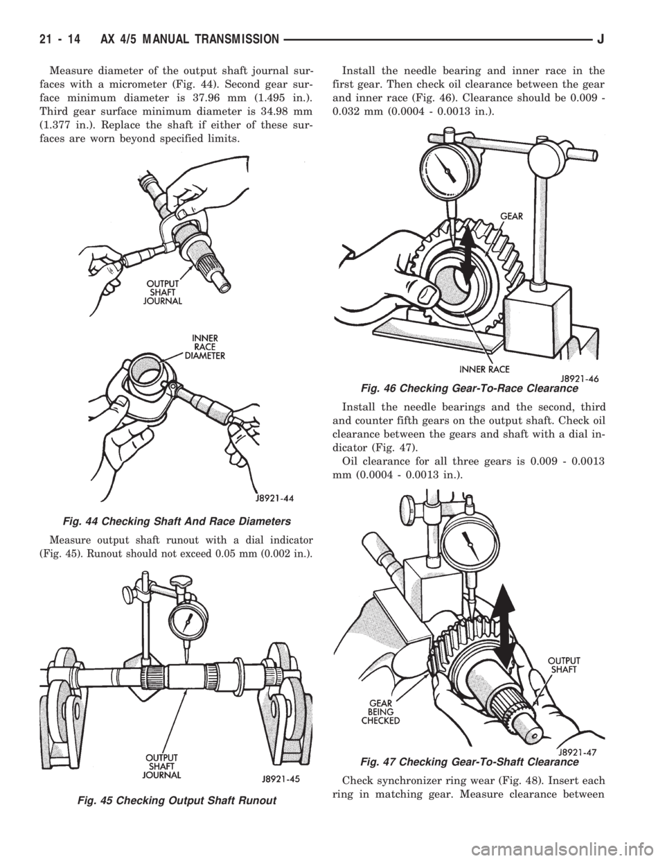
Measure diameter of the output shaft journal sur-
faces with a micrometer (Fig. 44). Second gear sur-
face minimum diameter is 37.96 mm (1.495 in.).
Third gear surface minimum diameter is 34.98 mm
(1.377 in.). Replace the shaft if either of these sur-
faces are worn beyond specified limits.
Measure output shaft runout with a dial indicator
(Fig. 45). Runout should not exceed 0.05 mm (0.002 in.).
Install the needle bearing and inner race in the
first gear. Then check oil clearance between the gear
and inner race (Fig. 46). Clearance should be 0.009 -
0.032 mm (0.0004 - 0.0013 in.).
Install the needle bearings and the second, third
and counter fifth gears on the output shaft. Check oil
clearance between the gears and shaft with a dial in-
dicator (Fig. 47).
Oil clearance for all three gears is 0.009 - 0.0013
mm (0.0004 - 0.0013 in.).
Check synchronizer ring wear (Fig. 48). Insert each
ring in matching gear. Measure clearance between
Fig. 44 Checking Shaft And Race Diameters
Fig. 45 Checking Output Shaft Runout
Fig. 46 Checking Gear-To-Race Clearance
Fig. 47 Checking Gear-To-Shaft Clearance
21 - 14 AX 4/5 MANUAL TRANSMISSIONJ
Page 1127 of 1784
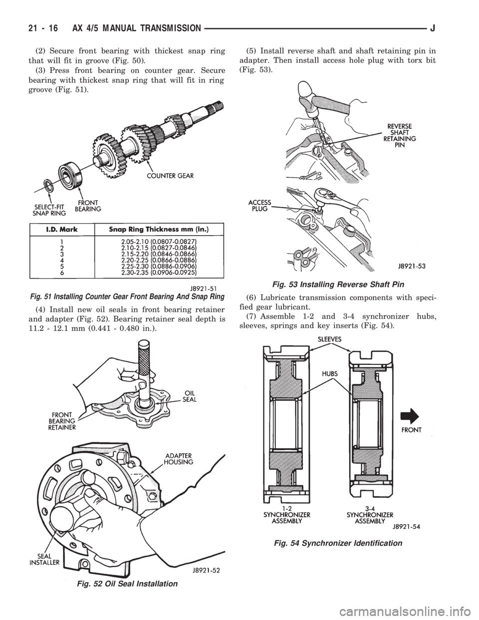
(2) Secure front bearing with thickest snap ring
that will fit in groove (Fig. 50).
(3) Press front bearing on counter gear. Secure
bearing with thickest snap ring that will fit in ring
groove (Fig. 51).
(4) Install new oil seals in front bearing retainer
and adapter (Fig. 52). Bearing retainer seal depth is
11.2 - 12.1 mm (0.441 - 0.480 in.).(5) Install reverse shaft and shaft retaining pin in
adapter. Then install access hole plug with torx bit
(Fig. 53).
(6) Lubricate transmission components with speci-
fied gear lubricant.
(7) Assemble 1-2 and 3-4 synchronizer hubs,
sleeves, springs and key inserts (Fig. 54).
Fig. 51 Installing Counter Gear Front Bearing And Snap Ring
Fig. 52 Oil Seal Installation
Fig. 53 Installing Reverse Shaft Pin
Fig. 54 Synchronizer Identification
21 - 16 AX 4/5 MANUAL TRANSMISSIONJ
Page 1132 of 1784
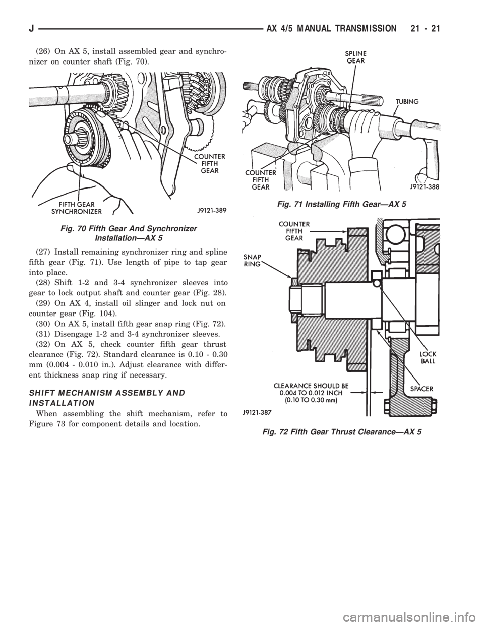
(26) On AX 5, install assembled gear and synchro-
nizer on counter shaft (Fig. 70).
(27) Install remaining synchronizer ring and spline
fifth gear (Fig. 71). Use length of pipe to tap gear
into place.
(28) Shift 1-2 and 3-4 synchronizer sleeves into
gear to lock output shaft and counter gear (Fig. 28).
(29) On AX 4, install oil slinger and lock nut on
counter gear (Fig. 104).
(30) On AX 5, install fifth gear snap ring (Fig. 72).
(31) Disengage 1-2 and 3-4 synchronizer sleeves.
(32) On AX 5, check counter fifth gear thrust
clearance (Fig. 72). Standard clearance is 0.10 - 0.30
mm (0.004 - 0.010 in.). Adjust clearance with differ-
ent thickness snap ring if necessary.
SHIFT MECHANISM ASSEMBLY AND
INSTALLATION
When assembling the shift mechanism, refer to
Figure 73 for component details and location.
Fig. 70 Fifth Gear And Synchronizer
InstallationÐAX 5
Fig. 71 Installing Fifth GearÐAX 5
Fig. 72 Fifth Gear Thrust ClearanceÐAX 5
JAX 4/5 MANUAL TRANSMISSION 21 - 21
Page 1144 of 1784
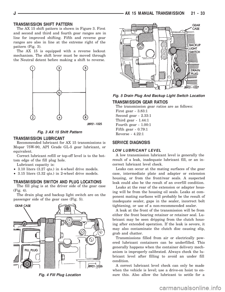
TRANSMISSION SHIFT PATTERN
The AX 15 shift pattern is shown in Figure 3. First
and second and third and fourth gear ranges are in
line for improved shifting. Fifth and reverse gear
ranges are also in line at the extreme right of the
pattern (Fig. 3).
The AX 15 is equipped with a reverse lockout
mechanism. The shift lever must be moved through
the Neutral detent before making a shift to reverse.
TRANSMISSION LUBRICANT
Recommended lubricant for AX 15 transmissions is
Mopar 75W-90, API Grade GL-5 gear lubricant, or
equivalent.
Correct lubricant refill or top-off level is to the bot-
tom edge of the fill plug hole.
Lubricant capacity is:
²3.10 liters (3.27 qts.) in 4-wheel drive models.
²3.15 liters (3.32 qts.) in 2-wheel drive models.
TRANSMISSION SWITCH AND PLUG LOCATIONS
The fill plug is at the driver side of the gear case
(Fig. 4).
The drain plug and backup light switch are on the
passenger side of the gear case (Fig. 5).
TRANSMISSION GEAR RATIOS
The transmission gear ratios are as follows:
First gear - 3.83:1
Second gear - 2.33:1
Third gear - 1.44:1
Fourth gear - 1.00:1
Fifth gear - 0.79:1
Reverse - 4.22:1
SERVICE DIAGNOSIS
LOW LUBRICANT LEVEL
A low transmission lubricant level is generally the
result of a leak, inadequate lubricant fill, or an in-
correct lubricant level check.
Leaks can occur at the mating surfaces of the gear
case, intermediate plate and adapter or extension
housing, or from the front/rear seals. A suspected
leak could also be the result of an overfill condition.
Leaks at the rear of the extension or adapter hous-
ing will be from the housing oil seals. Leaks at com-
ponent mating surfaces will probably be the result of
inadequate sealer, gaps in the sealer, incorrect bolt
tightening, or use of a non-recommended sealer.
A leak at the front of the transmission will be from
either the front bearing retainer or retainer seal. Lu-
bricant may be seen dripping from the clutch hous-
ing after extended operation. If the leak is severe, it
may also contaminate the clutch disc causing slip,
grab and chatter.
Transmissions filled from air or electrically pow-
ered lubricant containers can be underfilled. This
generally happens when the container delivery mech-
anism is improperly calibrated. Always check the lu-
bricant level after filling to avoid an under fill
condition.
A correct lubricant level check can only be made
when the vehicle is level; use a drive-on hoist to en-
sure this. Also allow the lubricant to settle for a
Fig. 3 AX 15 Shift Pattern
Fig. 4 Fill Plug Location
Fig. 5 Drain Plug And Backup Light Switch Location
JAX 15 MANUAL TRANSMISSION 21 - 33