1994 JEEP CHEROKEE oil
[x] Cancel search: oilPage 1207 of 1784
30RH/32RH IN-VEHICLE SERVICE
INDEX
page page
Checking Fluid Level and Condition........... 96
Front Band Adjustment.................... 99
Gearshift Linkage Adjustment (YJ)............ 96
Governor and Park Gear Service............ 101
Oil Filter Replacement.................... 100
Park Interlock Cable Adjustment (XJ)......... 97
Park Lock Component Replacement......... 102
Park/Neutral Position Switch Service......... 103
Rear Band Adjustment.................... 99
Recommended Fluid...................... 96
Servicing Transmission Cooler Lines and Fittings. 106
Shift Cable Adjustment (XJ)................ 97
Speedometer Service.................... 103
Transmission Cooler Flow Testing........... 106
Transmission Cooler Reverse Flushing....... 105
Transmission Throttle Cable Adjustment (XJ/YJ) . 98
Valve Body Installation................... 101
Valve Body Removal..................... 100
Valve Body Service...................... 100
RECOMMENDED FLUID
The recommended and preferred fluid for 30RH/
32RH transmissions is Mopar ATF Plus, Type 7176.
Mopar Dexron II is acceptable but should only be
used when ATF Plus is not available.
Transmission fluid capacity is approximately 17
pints (7.9 liters). This is the approximate amount of
fluid required to fill the transmission and torque con-
verter after overhaul.
CHECKING FLUID LEVEL AND CONDITION
(1) Position vehicle on flat, level surface. This is
important in obtaining an accurate fluid level check.
(2) To avoid false readings, which could produce
under or over fill condition, do not check level until
fluid is at normal operating temperature.
(3) Shift transmission into Neutral.
(4) Apply parking brakes.
(5) Operate engine at curb idle speed.
WARNING: WHEN PERFORMING UNDERHOOD OP-
ERATIONS WITH THE ENGINE RUNNING, KEEP
YOUR HANDS WELL AWAY FROM HOT OR ROTAT-
ING ENGINE COMPONENTS. DO NOT WEAR
LOOSE ARTICLES OF CLOTHING WHICH COULD
BECOME ENTANGLED IN ENGINE COMPONENTS
OR ACCESSORIES.
(6) Shift transmission through all gear ranges and
back to Neutral (leave engine running).
(7) Clean exterior of dipstick cap and fill tube be-
fore removing transmission dipstick.
(8) Remove dipstick and inspect fluid level.
²Correct level is to FULL mark
²Acceptable level is between ADD and FULL marks
(9) Check fluid condition. Fluid should be dark to
light red in color and free of dirt or debris.
(10) If fluid is discolored or smells burned but
transmission operation was OK, check cooler flow,
flush cooler and lines and change fluid and filter.
Then road test again to confirm proper operation.(11) If fluid is black or dark brown, burned/turned
to sludge, contains large quantities of metal or fric-
tion material particles, transmission will need over-
haul. Especially if problems were evident during
road test and preliminary diagnosis. Fluid cooler
should also be flow tested and flushed if necessary.
GEARSHIFT LINKAGE ADJUSTMENT (YJ)
(1) Check linkage adjustment by starting engine in
Park and Neutral.
(2) Adjustment is OK if engine starts only in park
and Neutral. Adjustment is incorrect if engine starts
in one but not both positions.
(3) If engine starts in any position other than Park
or Neutral, or if engine will not start at all, park/
neutral position switch may be faulty.
(4) Shift transmission into Park.
(5) Raise vehicle.
(6) Check condition of shift rods, bellcrank, bell-
crank brackets and linkage bushings/grommets (Fig.
1). Tighten, repair, replace worn, damaged parts. Do
not attempt adjustment if linkage components are
worn or damaged.
(7) Loosen shift rod trunnion lock bolt or nut. Be
sure upper shift rod slides freely in trunnion (Fig. 1).
Also be sure shift rods and bellcrank rotate freely
and do not bind at any point.
(8) Verify that manual lever is in Park detent
(Fig. 1). Move lever all the way rearward to be sure
it is in Park.
(9) Check for positive engagement of park lock by
attempting to rotate propeller shaft. Shaft will not
turn when park pawl is engaged.
(10) Adjust shift rod trunnion to a obtain free pin
fit in bellcrank arm and tighten trunnion lock bolt or
nut. Prevent shift rod from turning while tightening
bolt or nut. Gearshift linkage lash must be elimi-
nated to obtain proper adjustment. Eliminate lash by
pulling downward on shift rod and pressing upward
on bellcrank.
21 - 96 30RH/32RH IN-VEHICLE SERVICEJ
Page 1210 of 1784
THROTTLE CABLE ADJUSTMENT
PROCEDURE
Cable adjustment is performed entirely in the
engine compartment. It is not necessary to raise
the vehicle for access to any other components.
(1) Shift transmission into Park and shut engine
off.
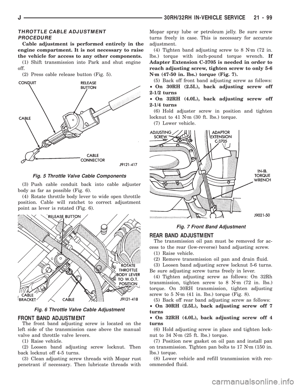
(2) Press cable release button (Fig. 5).
(3) Push cable conduit back into cable adjuster
body as far as possible (Fig. 6).
(4) Rotate throttle body lever to wide open throttle
position. Cable will ratchet to correct adjustment
point as lever is rotated (Fig. 6).
FRONT BAND ADJUSTMENT
The front band adjusting screw is located on the
left side of the transmission case above the manual
valve and throttle valve levers.
(1) Raise vehicle.
(2) Loosen band adjusting screw locknut. Then
back locknut off 4-5 turns.
(3) Clean adjusting screw threads with Mopar rust
penetrant if necessary. Then lubricate threads withMopar spray lube or petroleum jelly. Be sure screw
turns freely in case. This is necessary for accurate
adjustment.
(4) Tighten band adjusting screw to 8 Nzm (72 in.
lbs.) torque with inch-pound torque wrench.If
Adapter Extension C-3705 is needed in order to
reach adjusting screw, tighten screw to only 5-6
Nzm (47-50 in. lbs.) torque (Fig. 7).
(5) Back off front band adjusting screw as follows:
²On 30RH (2.5L), back adjusting screw off
2-1/2 turns
²On 32RH (4.0L), back adjusting screw off
2-1/4 turns
(6) Hold adjuster screw in position and tighten
locknut to 41 Nzm (30 ft. lbs.) torque.
(7) Lower vehicle.
REAR BAND ADJUSTMENT
The transmission oil pan must be removed for ac-
cess to the rear (low-reverse) band adjusting screw.
(1) Raise vehicle.
(2) Remove transmission oil pan and drain fluid.
(3) Loosen band adjusting screw locknut 5-6 turns.
Be sure adjusting screw turns freely in lever.
(4) Tighten adjusting screw as follows: On 32Rh
transmission, tighten screw to 8 Nzm (72 in. lbs.)
torque. On 30RH transmission, tighten adjusting
screw to 5 Nzm (41 in. lbs.) torque (Fig. 8).
(5) Back off rear band adjusting screw as follows:
²On 30RH (2.5L), back adjusting screw off 7
turns
²On 32RH (4.0L), back adjusting screw off 4
turns
(6) Hold adjusting screw in place and tighten lock-
nut to 34 Nzm (25 ft. lbs.) torque.
(7) Position new gasket on oil pan and install pan
on transmission. Tighten pan bolts to 17 Nzm (150 in.
lbs.) torque.
(8) Lower vehicle and refill transmission with rec-
ommended fluid.
Fig. 5 Throttle Valve Cable Components
Fig. 6 Throttle Valve Cable Adjustment
Fig. 7 Front Band Adjustment
J30RH/32RH IN-VEHICLE SERVICE 21 - 99
Page 1211 of 1784
OIL FILTER REPLACEMENT
(1) Raise vehicle.
(2) Remove oil pan and drain fluid.
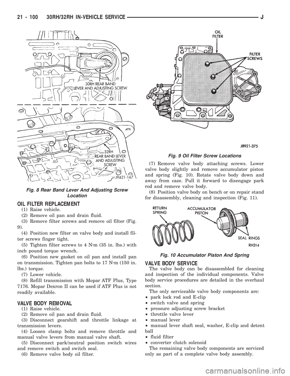
(3) Remove filter screws and remove oil filter (Fig.
9).
(4) Position new filter on valve body and install fil-
ter screws finger tight.
(5) Tighten filter screws to 4 Nzm (35 in. lbs.) with
inch pound torque wrench.
(6) Position new gasket on oil pan and install pan
on transmission. Tighten pan bolts to 17 Nzm (150 in.
lbs.) torque.
(7) Lower vehicle.
(8) Refill transmission with Mopar ATF Plus, Type
7176. Mopar Dexron II can be used if ATF Plus is not
readily available.
VALVE BODY REMOVAL
(1) Raise vehicle.
(2) Remove oil pan and drain fluid.
(3) Disconnect gearshift and throttle linkage at
transmission levers.
(4) Loosen clamp bolts and remove throttle and
manual valve levers from manual valve shaft.
(5) Disconnect park/neutral position switch wires
and remove switch and switch seal.
(6) Remove valve body oil filter.(7) Remove valve body attaching screws. Lower
valve body slightly and remove accumulator piston
and spring (Fig. 10). Rotate valve body down and
away from case. Pull it forward to disengage park
rod and remove valve body.
(8) Position valve body on bench or on repair stand
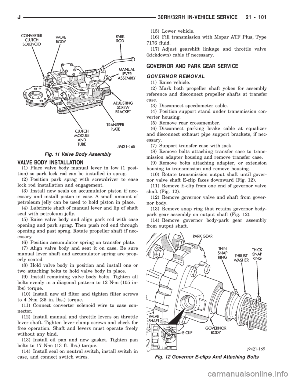
for disassembly, cleaning and inspection (Fig. 11).
VALVE BODY SERVICE
The valve body can be disassembled for cleaning
and inspection of the individual components. Valve
body service procedures are detailed in the overhaul
section.
The only serviceable valve body components are:
²park lock rod and E-clip
²switch valve and spring
²pressure adjusting screw bracket
²throttle valve lever
²manual lever
²manual lever shaft seal, washer, E-clip and detent
ball
²fluid filter
²converter clutch solenoid
The remaining valve body components are serviced
only as part of a complete valve body assembly.
Fig. 9 Oil Filter Screw Locations
Fig. 10 Accumulator Piston And Spring
Fig. 8 Rear Band Lever And Adjusting Screw
Location
21 - 100 30RH/32RH IN-VEHICLE SERVICEJ
Page 1212 of 1784
VALVE BODY INSTALLATION
(1) Place valve body manual lever in low (1 posi-
tion) so park lock rod can be installed in sprag.
(2) Position park sprag with screwdriver to ease
lock rod installation and engagement.
(3) Install new seals on accumulator piston if nec-
essary and install piston in case. A small amount of
petroleum jelly can be used to hold piston in place.
(4) Lubricate shaft of manual lever and lip of shaft
seal with petroleum jelly.
(5) Raise valve body and align park rod with case
opening and park sprag. Then push rod end through
opening and past sprag. Rotate propeller shaft if nec-
essary.
(6) Position accumulator spring on transfer plate.
(7) Align valve body and seat it on case. Be sure
manual lever shaft and accumulator spring are prop-
erly seated.
(8) Hold valve body in position and install one or
two attaching bolts to hold valve body in place.
(9) Install remaining valve body bolts. Tighten all
bolts evenly in a diagonal pattern to 12 Nzm (105 in-
lbs) torque.
(10) Install new oil filter and tighten filter screws
to4Nzm (35 in. lbs.) torque.
(11) Connect converter solenoid wire to case con-
nector.
(12) Install manual and throttle levers on throttle
lever shaft. Tighten lever clamp screws and check for
free operation. Shaft and levers must operate freely
without any bind.
(13) Install oil pan and new gasket. Tighten pan
bolts to 17 Nzm (13 ft. lbs.) torque.
(14) Install seal on neutral switch, install switch in
case, and connect switch wires.(15) Lower vehicle.
(16) Fill transmission with Mopar ATF Plus, Type
7176 fluid.
(17) Adjust gearshift linkage and throttle valve
(kickdown) cable if necessary.
GOVERNOR AND PARK GEAR SERVICE
GOVERNOR REMOVAL
(1) Raise vehicle.
(2) Mark both propeller shaft yokes for assembly
reference and disconnect propeller shafts at transfer
case.
(3) Disconnect speedometer cable.
(4) Position support stand under transmission con-
verter housing.
(5) Remove rear crossmember.
(6) Disconnect parking brake cable at equalizer
and disconnect exhaust pipe support brackets, if nec-
essary.
(7) Support transfer case with jack.
(8) Remove bolts attaching transfer case to trans-
mission adapter housing and remove transfer case.
(9) Remove bolts attaching adapter, or extension
housing to transmission and remove housing.
(10) Rotate transmission output shaft until gover-
nor valve shaft E-clip faces downward (Fig. 12).
(11) Remove E-clip from one end of governor valve
shaft (Fig. 12).
(12) Remove governor valve and shaft from gover-
nor body.
(13) Remove snap ring that retains governor body-
park gear assembly on output shaft (Fig. 12).
(14) Remove governor body-park gear assembly
from output shaft.
Fig. 12 Governor E-clips And Attaching Bolts
Fig. 11 Valve Body Assembly
J30RH/32RH IN-VEHICLE SERVICE 21 - 101
Page 1213 of 1784
GOVERNOR DISASSEMBLY
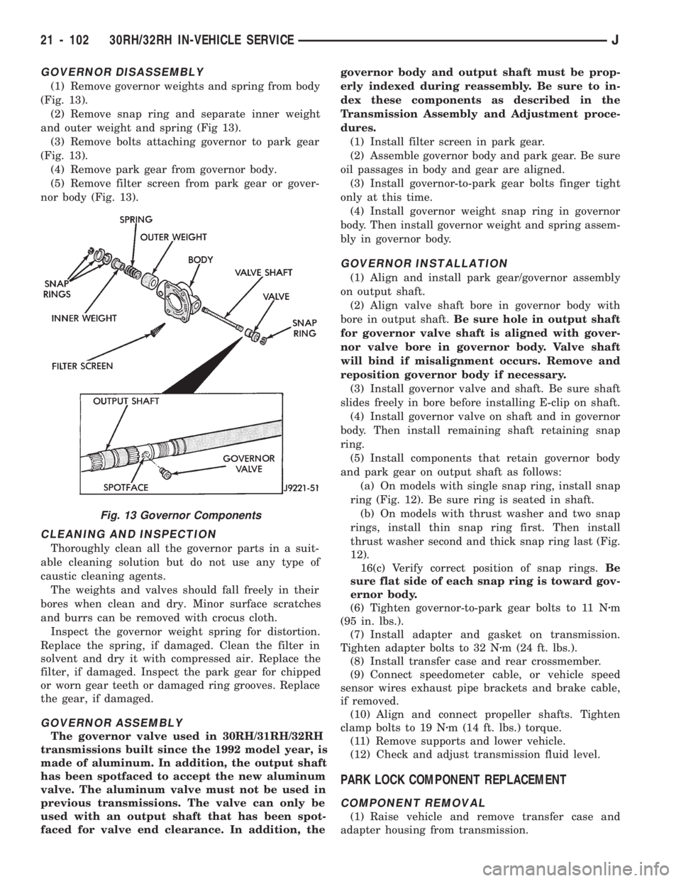
(1) Remove governor weights and spring from body
(Fig. 13).
(2) Remove snap ring and separate inner weight
and outer weight and spring (Fig 13).
(3) Remove bolts attaching governor to park gear
(Fig. 13).
(4) Remove park gear from governor body.
(5) Remove filter screen from park gear or gover-
nor body (Fig. 13).
CLEANING AND INSPECTION
Thoroughly clean all the governor parts in a suit-
able cleaning solution but do not use any type of
caustic cleaning agents.
The weights and valves should fall freely in their
bores when clean and dry. Minor surface scratches
and burrs can be removed with crocus cloth.
Inspect the governor weight spring for distortion.
Replace the spring, if damaged. Clean the filter in
solvent and dry it with compressed air. Replace the
filter, if damaged. Inspect the park gear for chipped
or worn gear teeth or damaged ring grooves. Replace
the gear, if damaged.
GOVERNOR ASSEMBLY
The governor valve used in 30RH/31RH/32RH
transmissions built since the 1992 model year, is
made of aluminum. In addition, the output shaft
has been spotfaced to accept the new aluminum
valve. The aluminum valve must not be used in
previous transmissions. The valve can only be
used with an output shaft that has been spot-
faced for valve end clearance. In addition, thegovernor body and output shaft must be prop-
erly indexed during reassembly. Be sure to in-
dex these components as described in the
Transmission Assembly and Adjustment proce-
dures.
(1) Install filter screen in park gear.
(2) Assemble governor body and park gear. Be sure
oil passages in body and gear are aligned.
(3) Install governor-to-park gear bolts finger tight
only at this time.
(4) Install governor weight snap ring in governor
body. Then install governor weight and spring assem-
bly in governor body.
GOVERNOR INSTALLATION
(1) Align and install park gear/governor assembly
on output shaft.
(2) Align valve shaft bore in governor body with
bore in output shaft.Be sure hole in output shaft
for governor valve shaft is aligned with gover-
nor valve bore in governor body. Valve shaft
will bind if misalignment occurs. Remove and
reposition governor body if necessary.
(3) Install governor valve and shaft. Be sure shaft
slides freely in bore before installing E-clip on shaft.
(4) Install governor valve on shaft and in governor
body. Then install remaining shaft retaining snap
ring.
(5) Install components that retain governor body
and park gear on output shaft as follows:
(a) On models with single snap ring, install snap
ring (Fig. 12). Be sure ring is seated in shaft.
(b) On models with thrust washer and two snap
rings, install thin snap ring first. Then install
thrust washer second and thick snap ring last (Fig.
12).
16(c) Verify correct position of snap rings.Be
sure flat side of each snap ring is toward gov-
ernor body.
(6) Tighten governor-to-park gear bolts to 11 Nzm
(95 in. lbs.).
(7) Install adapter and gasket on transmission.
Tighten adapter bolts to 32 Nzm (24 ft. lbs.).
(8) Install transfer case and rear crossmember.
(9) Connect speedometer cable, or vehicle speed
sensor wires exhaust pipe brackets and brake cable,
if removed.
(10) Align and connect propeller shafts. Tighten
clamp bolts to 19 Nzm (14 ft. lbs.) torque.
(11) Remove supports and lower vehicle.
(12) Check and adjust transmission fluid level.
PARK LOCK COMPONENT REPLACEMENT
COMPONENT REMOVAL
(1) Raise vehicle and remove transfer case and
adapter housing from transmission.
Fig. 13 Governor Components
21 - 102 30RH/32RH IN-VEHICLE SERVICEJ
Page 1216 of 1784
(10) Install speedometer adapter clamp and retain-
ing screw. Tighten clamp screw to 10-12 Nzm (90-110
in. lbs.) torque.
(11) Connect wires to vehicle speed sensor.
(12) Lower vehicle and top off transmission fluid
level if necessary.
SPEEDOMETER COMPONENT REMOVAL
(TWO-PIECE SENSOR)
(1) Raise vehicle.
(2) Disconnect speed sensor wires.
(3) Remove bolt attaching vehicle speed sensor to
sensor adapter. Then slide sensor out of adapter.
(4) Inspect speed sensor mounting area in sensor
adapter. If transmission fluid is found in this area,
oil seal in metal speedometer adapter is leaking and
will have to be replaced.
(5) Remove speedometer adapter clamp bolt and
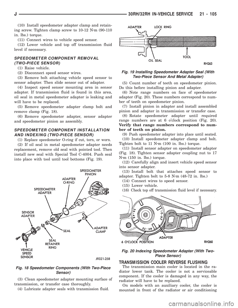
remove clamp (Fig. 18).
(6) Remove speedometer adapter, sensor adapter
and speedometer pinion as assembly.
SPEEDOMETER COMPONENT INSTALLATION
AND INDEXING (TWO-PIECE SENSOR)
(1) Replace speedometer O-ring if cut, torn, or worn.
(2) If oil seal in metal speedometer adapter needs
replacement, remove old seal with pointed tool. Then
install new seal with Special Tool C-4004. Push seal
into place with tool until tool bottoms (Fig. 19).
(3) Clean speedometer adapter mounting surface of
transmission, or transfer case thoroughly.
(4) Lubricate adapter seals with transmission fluid.
(5) Count number of teeth on speedometer pinion.
Do this before installing pinion and adapter.
(6) Note range numbers on face of speedometer
adapter (Fig. 20). These numbers correspond to num-
ber of teeth on speedometer pinion.
(7) Install pinion in adapter and install assembled
pinion and adapter in transmission or transfer case.
(8) Rotate speedometer adapter until required
range numbers are at 6 o'clock position (Fig. 20).
Verify that range numbers correspond to num-
ber of teeth on pinion.
(9) Push speedometer adapter into place until seated.
(10) Install speedometer adapter clamp and bolt.
Tighten bolt to 11 Nzm (100 in. lbs.) torque.
(11) Install sensor adapter on speedometer adapter
(Fig. 18). Tighten sensor adapter coupling nut to 17
Nzm (150 in. lbs.) torque.
(12) Carefully align and insert vehicle speed sensor
into sensor adapter.
(13) Install bolt that attaches speed sensor to
adapter. Tighten bolt to 5-8 Nzm (48-72 in. lbs.)
(14) Connect wires to speed sensor.
(15) Lower vehicle.
(16) Check top off transmission fluid level if necessary.
TRANSMISSION COOLER REVERSE FLUSHING
The transmission main cooler is located in the ra-
diator lower tank. The cooler is not a serviceable
component. If the cooler is damaged in any way, the
radiator will have to be replaced.
On models with an auxiliary cooler, the cooler is
mounted in front of the radiator or air conditioningFig. 18 Speedometer Components (With Two-Piece
Sensor)
Fig. 19 Installing Speedometer Adapter Seal (With
Two-Piece Sensor And Metal Adapter)
Fig. 20 Indexing Speedometer Adapter (With Two-
Piece Sensor)
J30RH/32RH IN-VEHICLE SERVICE 21 - 105
Page 1217 of 1784
condenser. The auxiliary cooler is a serviceable com-
ponent and can be repaired if necessary.
The main and auxiliary coolers should be thor-
oughly reverse flushed if a transmission failure
contaminates the fluid. Reverse flushing the cooler
and lines will prevent sludge and particles from
flowing back into the transmission after repair.
The same flushing procedure is used for main and
auxiliary coolers. Pressure equipment is preferred for
reverse flushing. However, reverse flushing can be
performed using hand operated equipment as de-
scribed in the following procedure.
REVERSE FLUSHING PROCEDURE
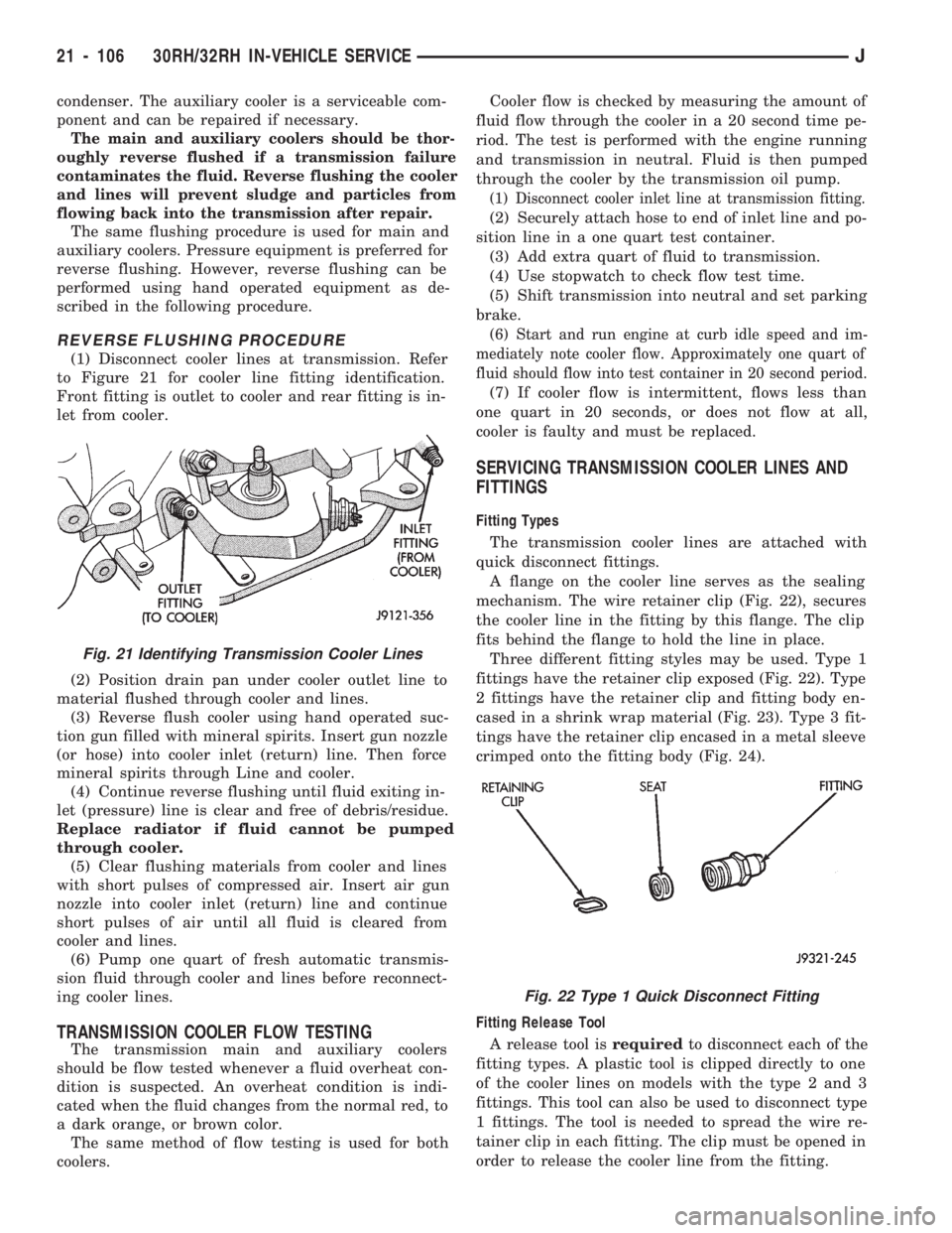
(1) Disconnect cooler lines at transmission. Refer
to Figure 21 for cooler line fitting identification.
Front fitting is outlet to cooler and rear fitting is in-
let from cooler.
(2) Position drain pan under cooler outlet line to
material flushed through cooler and lines.
(3) Reverse flush cooler using hand operated suc-
tion gun filled with mineral spirits. Insert gun nozzle
(or hose) into cooler inlet (return) line. Then force
mineral spirits through Line and cooler.
(4) Continue reverse flushing until fluid exiting in-
let (pressure) line is clear and free of debris/residue.
Replace radiator if fluid cannot be pumped
through cooler.
(5) Clear flushing materials from cooler and lines
with short pulses of compressed air. Insert air gun
nozzle into cooler inlet (return) line and continue
short pulses of air until all fluid is cleared from
cooler and lines.
(6) Pump one quart of fresh automatic transmis-
sion fluid through cooler and lines before reconnect-
ing cooler lines.
TRANSMISSION COOLER FLOW TESTING
The transmission main and auxiliary coolers
should be flow tested whenever a fluid overheat con-
dition is suspected. An overheat condition is indi-
cated when the fluid changes from the normal red, to
a dark orange, or brown color.
The same method of flow testing is used for both
coolers.Cooler flow is checked by measuring the amount of
fluid flow through the cooler in a 20 second time pe-
riod. The test is performed with the engine running
and transmission in neutral. Fluid is then pumped
through the cooler by the transmission oil pump.
(1) Disconnect cooler inlet line at transmission fitting.
(2) Securely attach hose to end of inlet line and po-
sition line in a one quart test container.
(3) Add extra quart of fluid to transmission.
(4) Use stopwatch to check flow test time.
(5) Shift transmission into neutral and set parking
brake.
(6) Start and run engine at curb idle speed and im-
mediately note cooler flow. Approximately one quart of
fluid should flow into test container in 20 second period.
(7) If cooler flow is intermittent, flows less than
one quart in 20 seconds, or does not flow at all,
cooler is faulty and must be replaced.
SERVICING TRANSMISSION COOLER LINES AND
FITTINGS
Fitting Types
The transmission cooler lines are attached with
quick disconnect fittings.
A flange on the cooler line serves as the sealing
mechanism. The wire retainer clip (Fig. 22), secures
the cooler line in the fitting by this flange. The clip
fits behind the flange to hold the line in place.
Three different fitting styles may be used. Type 1
fittings have the retainer clip exposed (Fig. 22). Type
2 fittings have the retainer clip and fitting body en-
cased in a shrink wrap material (Fig. 23). Type 3 fit-
tings have the retainer clip encased in a metal sleeve
crimped onto the fitting body (Fig. 24).
Fitting Release Tool
A release tool isrequiredto disconnect each of the
fitting types. A plastic tool is clipped directly to one
of the cooler lines on models with the type 2 and 3
fittings. This tool can also be used to disconnect type
1 fittings. The tool is needed to spread the wire re-
tainer clip in each fitting. The clip must be opened in
order to release the cooler line from the fitting.
Fig. 21 Identifying Transmission Cooler Lines
Fig. 22 Type 1 Quick Disconnect Fitting
21 - 106 30RH/32RH IN-VEHICLE SERVICEJ
Page 1219 of 1784
30RH/32RH TRANSMISSION REMOVAL AND INSTALLATION
INDEX
page page
ConverterÐPump SealÐDrive Plate Service . . . 109
Transmission and Converter Installation....... 109Transmission and Converter Removal........ 108
TRANSMISSION AND CONVERTER REMOVAL
(1) Remove fan shroud attaching bolts.
(2) Disconnect transmission fill tube at upper
bracket.
(3) Raise vehicle.
(4) Remove inspection cover from converter hous-
ing and remove skid plate for access, if necessary.
(5) Remove transmission fill tube and fill tube
O-ring.
(6) Remove starter motor.
(7) Mark propeller shafts and axle yokes for align-
ment reference.
(8) Disconnect propeller shafts at yokes. Secure
shafts to frame rails with wire.
(9) Disconnect exhaust pipes at exhaust manifolds,
if necessary.
(10) Drain transfer case lubricant.
(11) Disconnect vehicle speed sensor wires.
(12) Disconnect transfer case shift linkage.
(13) Disconnect gearshift linkage and throttle ca-
ble at transmission levers.
(14) Disconnect park/neutral position switch wires.
(15) Disconnect and remove crankshaft position
sensor. Retain sensor bolt for reinstallation.
CAUTION: The crankshaft position sensor can be
damaged during transmission removal (or installa-
tion) if the sensor is still bolted to the engine block.
To avoid damage, remove the sensor before remov-
ing the transmission.
(16) Remove converter housing access cover and
mark drive plate and converter for alignment refer-
ence.
(17) Remove bolts attaching converter to drive
plate.
(18) Support engine with support stand.
(19) Support transmission-transfer case assembly
with transmission jack. Secure transmission to jack
with safety chain.
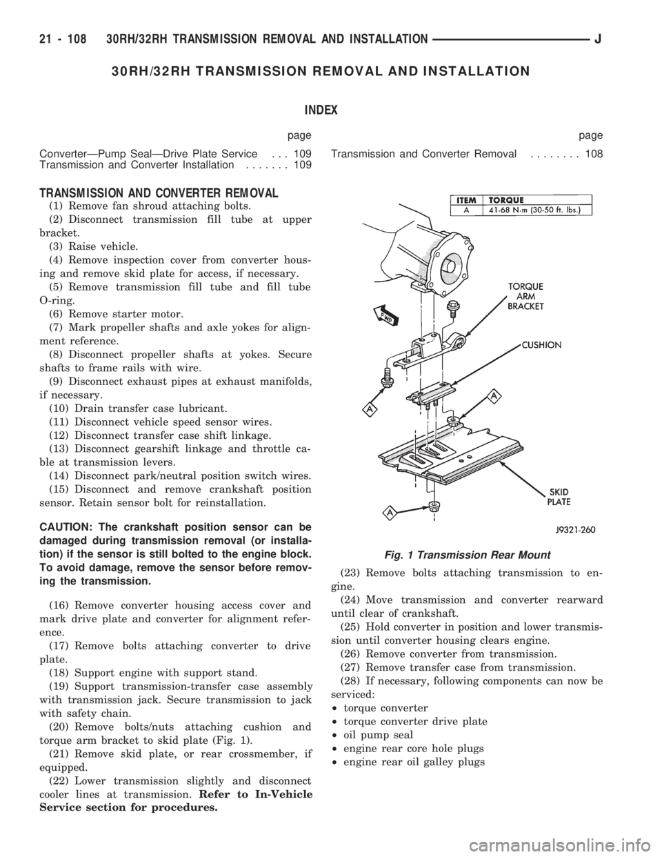
(20) Remove bolts/nuts attaching cushion and
torque arm bracket to skid plate (Fig. 1).
(21) Remove skid plate, or rear crossmember, if
equipped.
(22) Lower transmission slightly and disconnect
cooler lines at transmission.Refer to In-Vehicle
Service section for procedures.(23) Remove bolts attaching transmission to en-
gine.
(24) Move transmission and converter rearward
until clear of crankshaft.
(25) Hold converter in position and lower transmis-
sion until converter housing clears engine.
(26) Remove converter from transmission.
(27) Remove transfer case from transmission.
(28) If necessary, following components can now be
serviced:
²torque converter
²torque converter drive plate
²oil pump seal
²engine rear core hole plugs
²engine rear oil galley plugs
Fig. 1 Transmission Rear Mount
21 - 108 30RH/32RH TRANSMISSION REMOVAL AND INSTALLATIONJ