1994 JEEP CHEROKEE oil
[x] Cancel search: oilPage 1267 of 1784
AW-4 AUTOMATIC TRANSMISSION
CONTENTS
page page
AW-4 IN-VEHICLE SERVICE............. 173
AW-4 TRANSMISSION DIAGNOSIS........ 167
AW-4 TRANSMISSION OVERHAUL........ 192
AW-4 TRANSMISSION REMOVAL AND
INSTALLATION....................... 189GENERAL INFORMATION................ 156
TRANSMISSION/TRANSFER CASE
SPECIFICATIONS..................... 320
GENERAL INFORMATION
INDEX
page page
Components and Operation................ 157
Description............................ 156
FirstÐThirdÐReverse Gear Components...... 159
Fourth Gear Overdrive Components......... 158
Geartrain Operation and Application Charts.... 159Hydraulic System........................ 160
Torque Converter........................ 158
Transmission Identification................. 157
Transmission Ranges and Shift Lever Positions . 157
DESCRIPTION
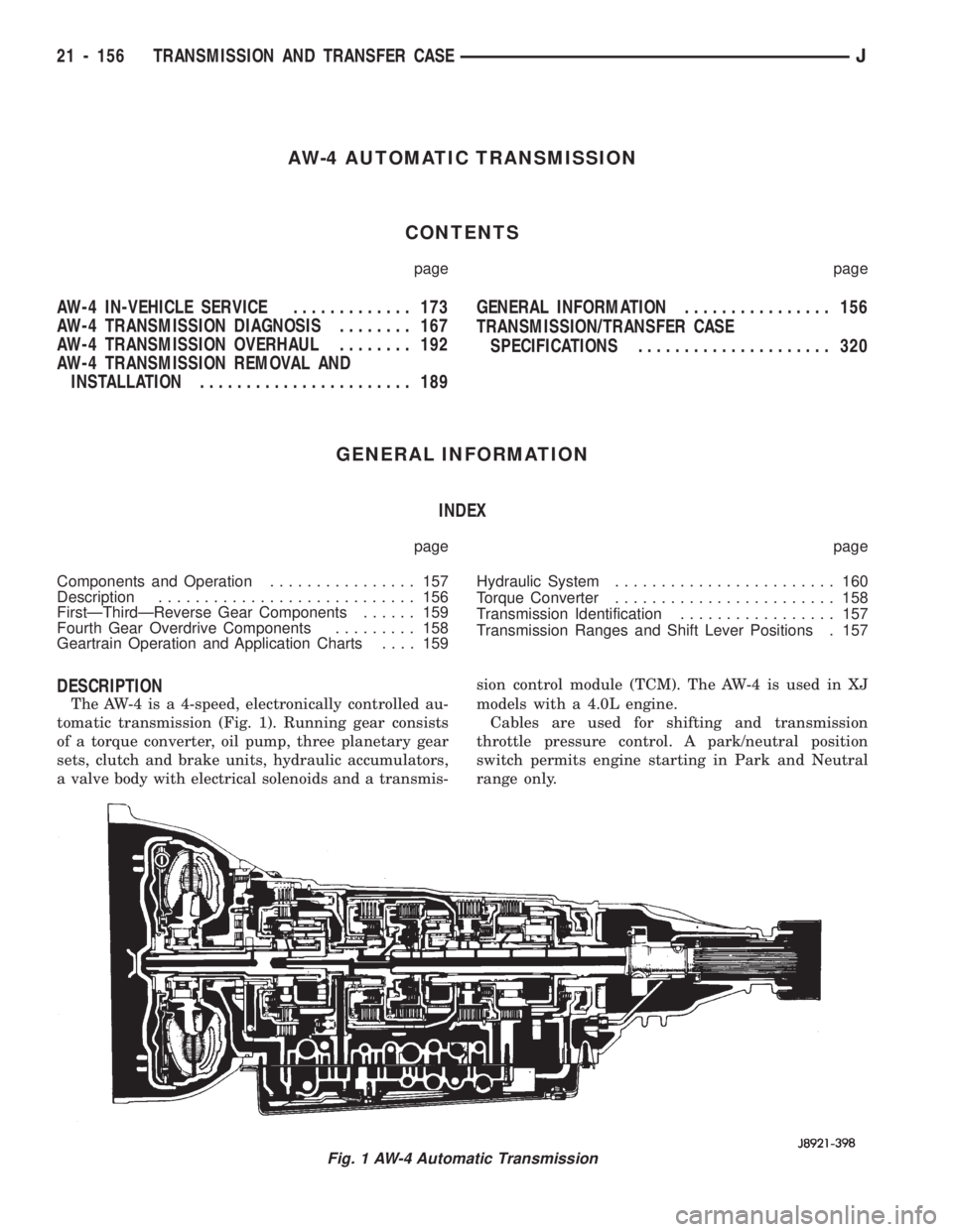
The AW-4 is a 4-speed, electronically controlled au-
tomatic transmission (Fig. 1). Running gear consists
of a torque converter, oil pump, three planetary gear
sets, clutch and brake units, hydraulic accumulators,
a valve body with electrical solenoids and a transmis-sion control module (TCM). The AW-4 is used in XJ
models with a 4.0L engine.
Cables are used for shifting and transmission
throttle pressure control. A park/neutral position
switch permits engine starting in Park and Neutral
range only.
Fig. 1 AW-4 Automatic Transmission
21 - 156 TRANSMISSION AND TRANSFER CASEJ
Page 1271 of 1784
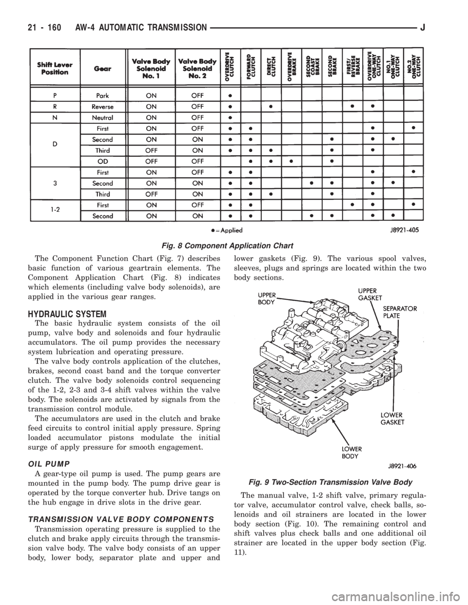
The Component Function Chart (Fig. 7) describes
basic function of various geartrain elements. The
Component Application Chart (Fig. 8) indicates
which elements (including valve body solenoids), are
applied in the various gear ranges.
HYDRAULIC SYSTEM
The basic hydraulic system consists of the oil
pump, valve body and solenoids and four hydraulic
accumulators. The oil pump provides the necessary
system lubrication and operating pressure.
The valve body controls application of the clutches,
brakes, second coast band and the torque converter
clutch. The valve body solenoids control sequencing
of the 1-2, 2-3 and 3-4 shift valves within the valve
body. The solenoids are activated by signals from the
transmission control module.
The accumulators are used in the clutch and brake
feed circuits to control initial apply pressure. Spring
loaded accumulator pistons modulate the initial
surge of apply pressure for smooth engagement.
OIL PUMP
A gear-type oil pump is used. The pump gears are
mounted in the pump body. The pump drive gear is
operated by the torque converter hub. Drive tangs on
the hub engage in drive slots in the drive gear.
TRANSMISSION VALVE BODY COMPONENTS
Transmission operating pressure is supplied to the
clutch and brake apply circuits through the transmis-
sion valve body. The valve body consists of an upper
body, lower body, separator plate and upper andlower gaskets (Fig. 9). The various spool valves,
sleeves, plugs and springs are located within the two
body sections.
The manual valve, 1-2 shift valve, primary regula-
tor valve, accumulator control valve, check balls, so-
lenoids and oil strainers are located in the lower
body section (Fig. 10). The remaining control and
shift valves plus check balls and one additional oil
strainer are located in the upper body section (Fig.
11).
Fig. 8 Component Application Chart
Fig. 9 Two-Section Transmission Valve Body
21 - 160 AW-4 AUTOMATIC TRANSMISSIONJ
Page 1276 of 1784
De-energizing the solenoid causes the drain port to
close. Line pressure then moves the valve down ex-
posing the overdrive brake accumulator feed port for
the shift to fourth gear.
In the 1-2 or 3 gearshift lever positions, line pres-
sure from the 2-3 shift valve is applied to the lower
end of the 3-4 valve. This holds the valve upward,
closing off the overdrive brake feed port preventing a
shift into fourth gear.
Second Coast Modulator Valve
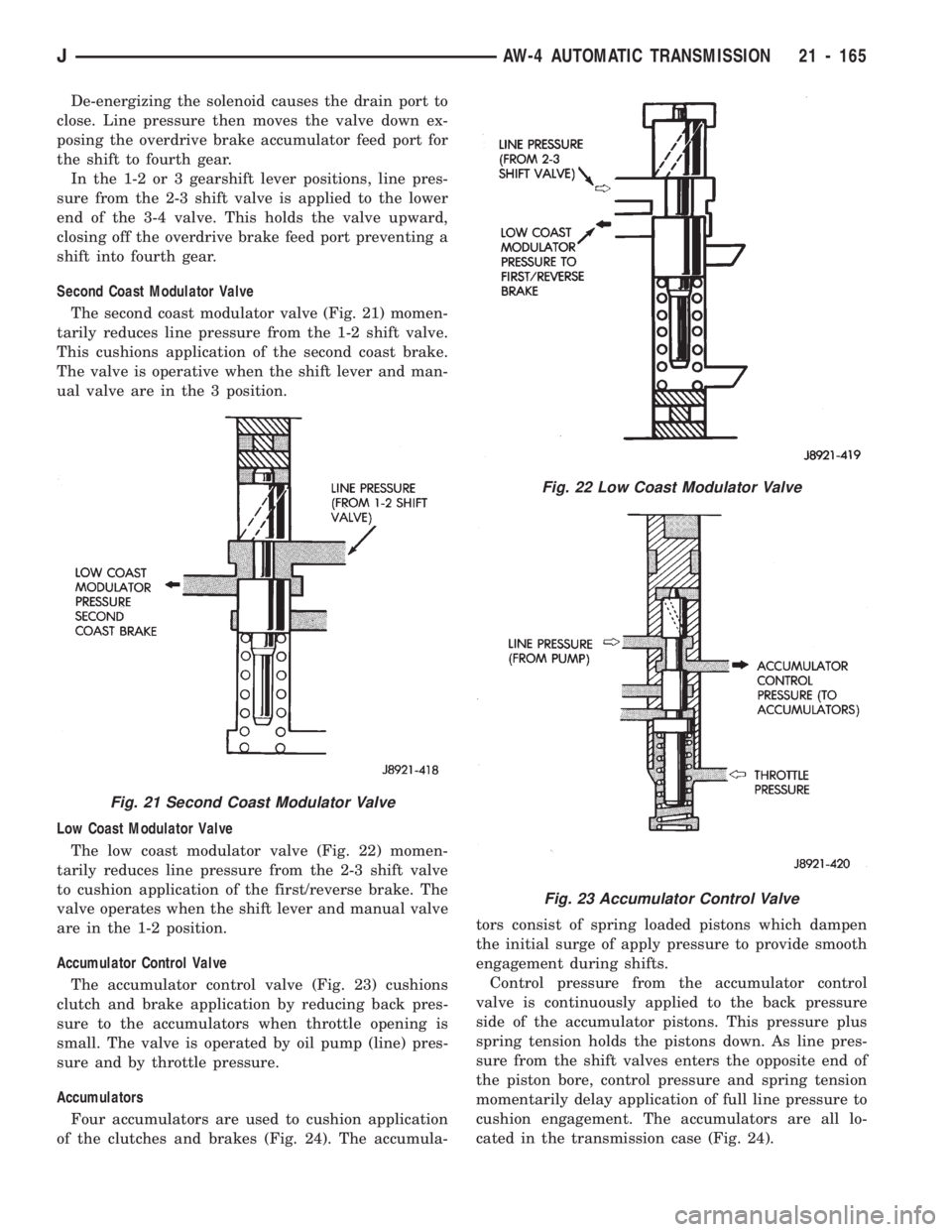
The second coast modulator valve (Fig. 21) momen-
tarily reduces line pressure from the 1-2 shift valve.
This cushions application of the second coast brake.
The valve is operative when the shift lever and man-
ual valve are in the 3 position.
Low Coast Modulator Valve
The low coast modulator valve (Fig. 22) momen-
tarily reduces line pressure from the 2-3 shift valve
to cushion application of the first/reverse brake. The
valve operates when the shift lever and manual valve
are in the 1-2 position.
Accumulator Control Valve
The accumulator control valve (Fig. 23) cushions
clutch and brake application by reducing back pres-
sure to the accumulators when throttle opening is
small. The valve is operated by oil pump (line) pres-
sure and by throttle pressure.
Accumulators
Four accumulators are used to cushion application
of the clutches and brakes (Fig. 24). The accumula-tors consist of spring loaded pistons which dampen
the initial surge of apply pressure to provide smooth
engagement during shifts.
Control pressure from the accumulator control
valve is continuously applied to the back pressure
side of the accumulator pistons. This pressure plus
spring tension holds the pistons down. As line pres-
sure from the shift valves enters the opposite end of
the piston bore, control pressure and spring tension
momentarily delay application of full line pressure to
cushion engagement. The accumulators are all lo-
cated in the transmission case (Fig. 24).
Fig. 21 Second Coast Modulator Valve
Fig. 22 Low Coast Modulator Valve
Fig. 23 Accumulator Control Valve
JAW-4 AUTOMATIC TRANSMISSION 21 - 165
Page 1280 of 1784
PRESSURE TEST ANALYSIS
If pressures in D and Reverse are higher than
specified, check for the following:
²throttle cable loose, worn, binding or out of adjust-
ment
²throttle valve, downshift plug, throttle cam, or pri-
mary regulator valve are sticking, worn or damaged
If pressures in D and Reverse are lower than spec-
ified, check for following:
²throttle cable loose, worn, binding or out of adjust-
ment
²throttle valve, downshift plug, throttle cam stick-
ing, worn or damaged
²primary regulator valve sticking, worn, or dam-
aged
²oil pump gears or housing worn or damaged
²overdrive clutch worn or damaged
If pressures are low in D range only, check for fol-
lowing:
²forward clutch worn or damaged
²fluid leakage in D range circuit (component seal
and O-rings)
If pressures are low in Reverse only, check for fol-
lowing:
²shift cable and manual valve out of adjustment
²fluid leakage in reverse circuit (component seal
and O-rings)
²direct clutch worn or damaged
²first/reverse brake worn or damaged
TORQUE CONVERTER STALL TEST
Stall testing checks the holding ability of the trans-
mission clutches and brakes and of the torque con-
verter stator overrunning clutch.
(1) Be sure transmission fluid is at normal operat-
ing temperature.
(2) Connect tachometer to engine. Position tachom-
eter so it can be viewed from drivers seat.
(3) Apply parking brakes and block wheels.
(4) Apply and hold service brakes.
(5) Shift transfer case into 2H position. On models
with NP249 transfer case, leave transfer case in 4H
position.
(6) Start engine.
WARNING: DO NOT ALLOW ANYONE TO STAND AT
THE FRONT OR REAR OF THE VEHICLE DURING
THE TEST.
(7) Shift transmission into D range.
(8) Press accelerator pedal to wide open throttle
position and note maximum engine rpm. Stall speed
should be 2100 to 2400 rpm in D range.
CAUTION: Do not maintain wide open throttle for
more than 3-4 seconds at a time.(9) Release throttle and shift transmission into
Neutral. Allow transmission fluid to cool for 15-20
seconds.
(10) Shift transmission into Reverse.
(11) Press accelerator down to wide open throttle
position and note maximum engine rpm. Stall speed
should be 2100-to-2400 rpm in Reverse.
STALL SPEED TEST ANALYSIS
If engine rpm is lower than specified in D and Re-
verse, check for the following:
²engine output/performance insufficient
²stator overrunning clutch in torque converter not
holding if engine speed was 1500 rpm or less.
If stall speed in D range is higher than specified,
check for the following:
²line pressure low
²forward clutch slipping
²No. 2 one-way clutch not holding
²overdrive one-way clutch not holding
If stall speed in Reverse was higher than specified,
check for the following:
²line pressure low
²direct clutch slipping
²first/ reverse brake slipping
²overdrive one-way clutch not holding
If stall speeds were higher than specified in both D
and Reverse, check for the following:
²low fluid level
²line pressure low
²overdrive one-way clutch not holding
TIME LAG TEST
This test checks general condition of the overdrive
clutch, forward clutch, rear clutch and first/reverse
brake. Condition is indicated by the amount of time
required for clutch/brake engagement with the en-
gine at curb idle speed. Engagement time is mea-
sured for D and Reverse positions. A stop watch is
recommended for test accuracy.
TEST PROCEDURE
(1) Check and adjust transmission fluid level if
necessary.
(2) Bring transmission to normal operating tem-
perature.
(3) Apply parking brakes and turn off air condi-
tioning unit.
(4) Shift transfer case into 2H range. On models
with NP249 transfer case, leave transfer case in 4H
range.
(5) Start engine and check curb idle speed. Adjust
speed if necessary. Curb idle must be correct to en-
sure accurate test results.
(6) Shift transmission into Neutral and set stop
watch.
(7) During following test steps, start stop watch as
soon as shift lever reaches D and Reverse ranges.
JAW-4 TRANSMISSION DIAGNOSIS 21 - 169
Page 1284 of 1784
AW-4 IN-VEHICLE SERVICE
INDEX
page page
Accumulator Pistons and Springs........... 179
Adapter Housing Seal Replacement.......... 182
Checking Fluid Level and Condition.......... 173
Manual Valve Shaft Seal Replacement....... 178
Park Interlock Cable Adjustment............ 186
Park Rod and Pawl Service................ 181
Park/Neutral Position Switch............... 173
Second Coast Brake Servo................ 181
Shift Cable Adjustment................... 186
Speed Sensor.......................... 182Speed Sensor RotorÐSpeedometer Drive Gear . 183
Throttle Position Sensor (TPS) Service....... 184
Transmission Control Module (TCM) Service . . . 173
Transmission Cooler Line Fittings........... 187
Transmission Cooler Service............... 187
Transmission Throttle Cable Adjustment....... 185
Transmission Throttle Cable Replacement..... 184
Transmission Valve Body Installation......... 177
Transmission Valve Body Removal.......... 176
Transmission Valve Body Solenoids.......... 175
CHECKING FLUID LEVEL AND CONDITION
Recommended fluid for AW-4 transmissions is Mo-
par Dexron IIE/Mercon. Mopar Dexron II may be
used if Mercon fluid is not readily available.
CHECKING FLUID LEVEL
(1) Be sure transmission fluid is at normal operat-
ing temperature. Normal operating temperature is
reached after approximately 15 miles (25 km) of op-
eration.
(2) Position vehicle on level surface. This is impor-
tant for an accurate fluid level check.
(3) Shift transmission through all gear ranges and
back to Park.
(4) Apply parking brakes.
(5) Verify that transmission is in Park.
(6) Wipe off dipstick handle to prevent dirt from
entering fill tube. Then remove dipstick and check
fluid level and condition.
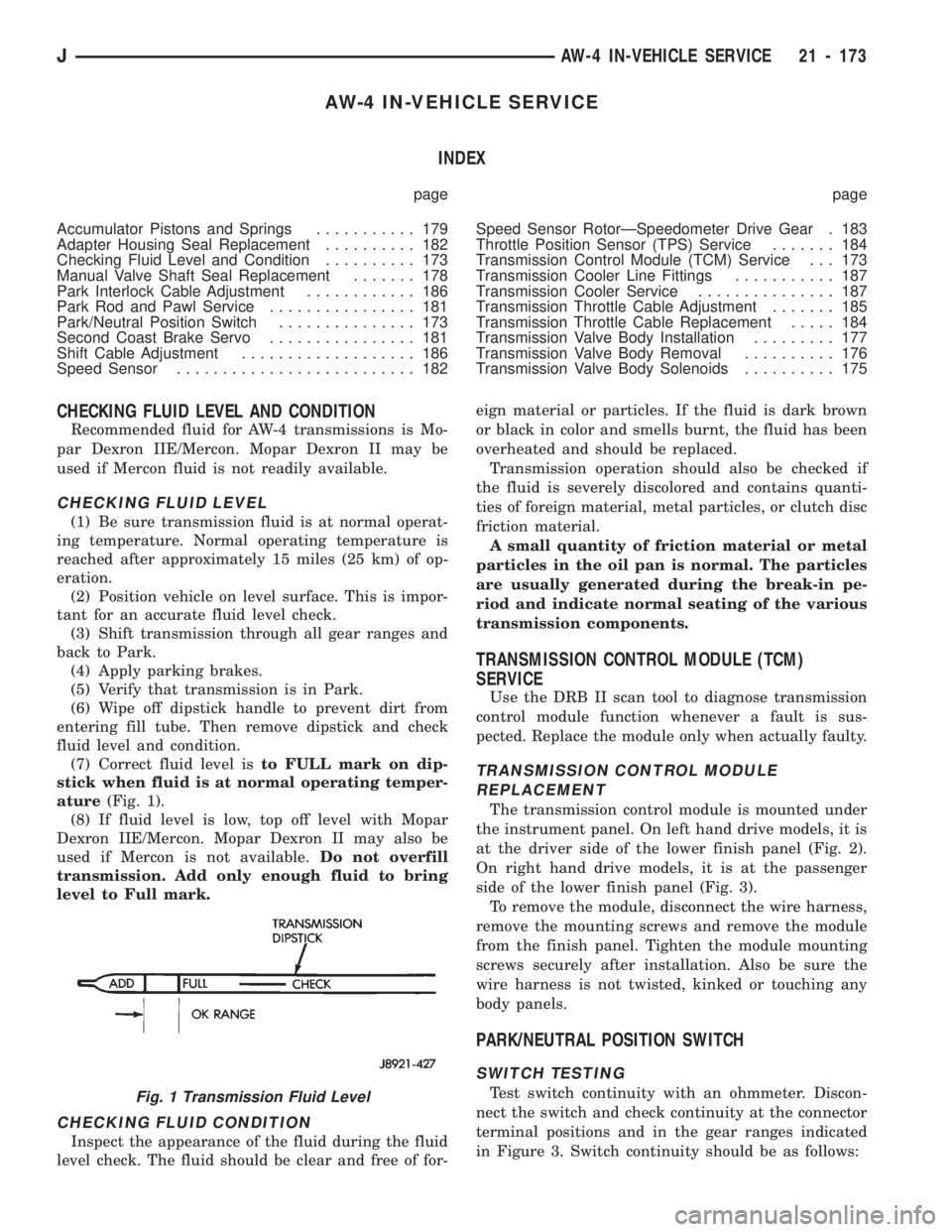
(7) Correct fluid level isto FULL mark on dip-
stick when fluid is at normal operating temper-
ature(Fig. 1).
(8) If fluid level is low, top off level with Mopar
Dexron IIE/Mercon. Mopar Dexron II may also be
used if Mercon is not available.Do not overfill
transmission. Add only enough fluid to bring
level to Full mark.
CHECKING FLUID CONDITION
Inspect the appearance of the fluid during the fluid
level check. The fluid should be clear and free of for-eign material or particles. If the fluid is dark brown
or black in color and smells burnt, the fluid has been
overheated and should be replaced.
Transmission operation should also be checked if
the fluid is severely discolored and contains quanti-
ties of foreign material, metal particles, or clutch disc
friction material.
A small quantity of friction material or metal
particles in the oil pan is normal. The particles
are usually generated during the break-in pe-
riod and indicate normal seating of the various
transmission components.
TRANSMISSION CONTROL MODULE (TCM)
SERVICE
Use the DRB II scan tool to diagnose transmission
control module function whenever a fault is sus-
pected. Replace the module only when actually faulty.
TRANSMISSION CONTROL MODULE
REPLACEMENT
The transmission control module is mounted under
the instrument panel. On left hand drive models, it is
at the driver side of the lower finish panel (Fig. 2).
On right hand drive models, it is at the passenger
side of the lower finish panel (Fig. 3).
To remove the module, disconnect the wire harness,
remove the mounting screws and remove the module
from the finish panel. Tighten the module mounting
screws securely after installation. Also be sure the
wire harness is not twisted, kinked or touching any
body panels.
PARK/NEUTRAL POSITION SWITCH
SWITCH TESTING
Test switch continuity with an ohmmeter. Discon-
nect the switch and check continuity at the connector
terminal positions and in the gear ranges indicated
in Figure 3. Switch continuity should be as follows:Fig. 1 Transmission Fluid Level
JAW-4 IN-VEHICLE SERVICE 21 - 173
Page 1286 of 1784
(8) Tighten switch adjusting bolt to 13 Nzm(9ft.
lbs.) torque.
(9) Bend at least two washer lock tabs over switch
attaching nut to secure it.
(10) Connect shift linkage rod to shift lever on left
side of case.
(11) Connect switch wires to harness and lower ve-
hicle.
(12) Check switch operation. Engine should start
in Park and Neutral only.
TRANSMISSION VALVE BODY SOLENOIDS
SOLENOID REMOVAL
(1) Remove transmission oil pan drain plug and
drain fluid.
(2) Remove pan bolts and remove oil pan.
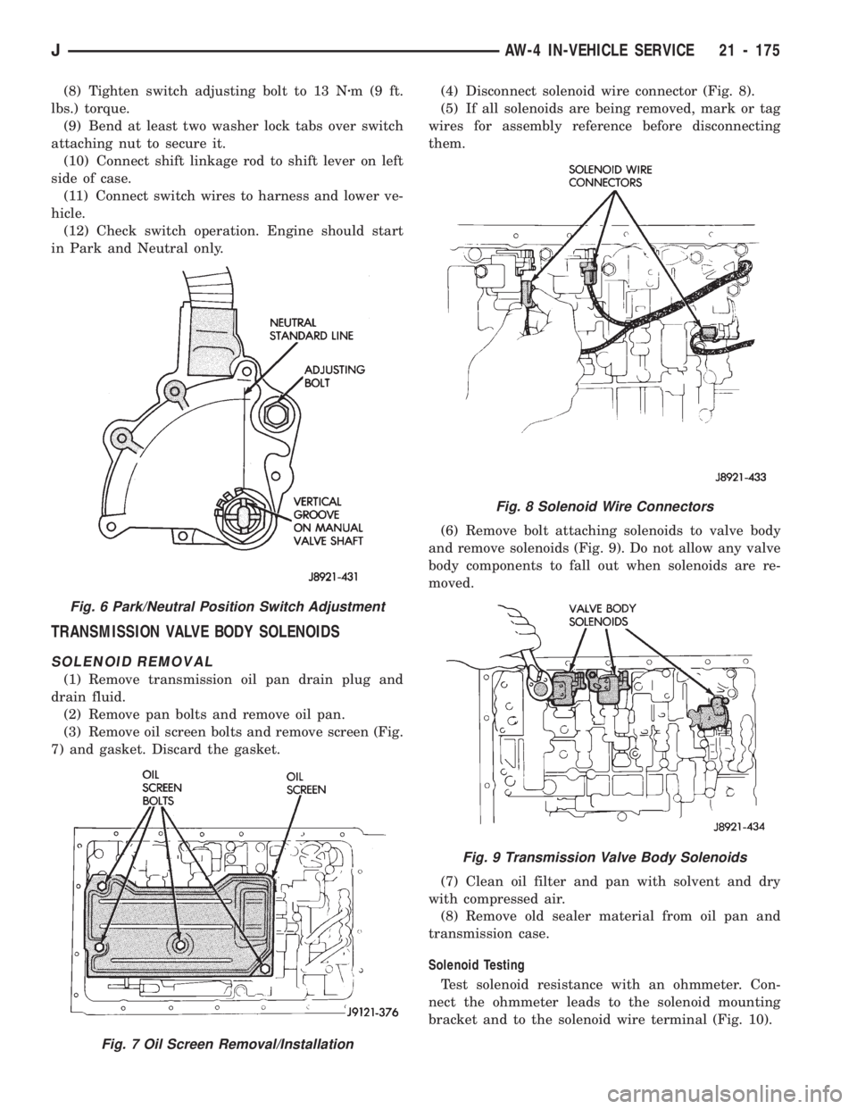
(3) Remove oil screen bolts and remove screen (Fig.
7) and gasket. Discard the gasket.(4) Disconnect solenoid wire connector (Fig. 8).
(5) If all solenoids are being removed, mark or tag
wires for assembly reference before disconnecting
them.
(6) Remove bolt attaching solenoids to valve body
and remove solenoids (Fig. 9). Do not allow any valve
body components to fall out when solenoids are re-
moved.
(7) Clean oil filter and pan with solvent and dry
with compressed air.
(8) Remove old sealer material from oil pan and
transmission case.
Solenoid Testing
Test solenoid resistance with an ohmmeter. Con-
nect the ohmmeter leads to the solenoid mounting
bracket and to the solenoid wire terminal (Fig. 10).
Fig. 8 Solenoid Wire Connectors
Fig. 9 Transmission Valve Body Solenoids
Fig. 6 Park/Neutral Position Switch Adjustment
Fig. 7 Oil Screen Removal/Installation
JAW-4 IN-VEHICLE SERVICE 21 - 175
Page 1287 of 1784
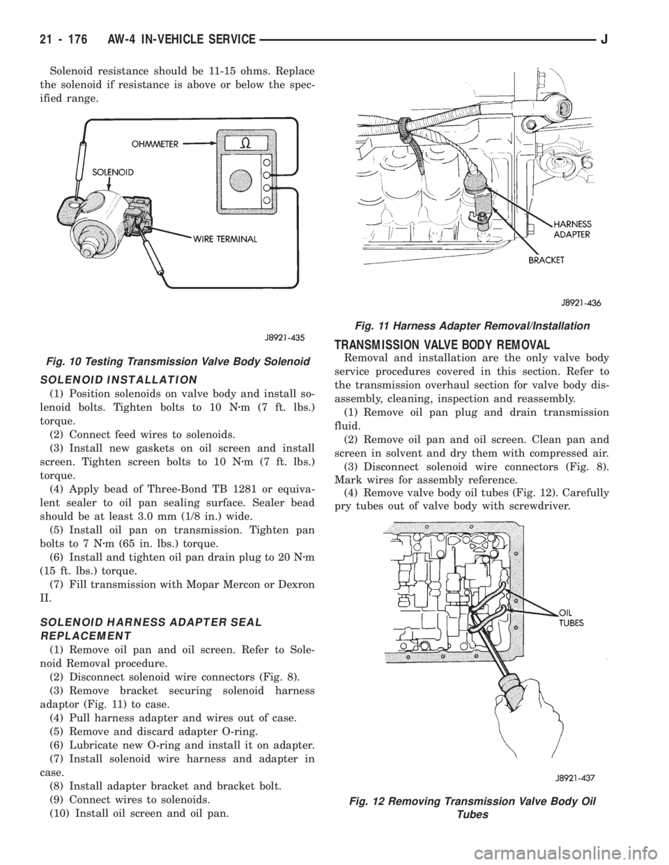
Solenoid resistance should be 11-15 ohms. Replace
the solenoid if resistance is above or below the spec-
ified range.
SOLENOID INSTALLATION
(1) Position solenoids on valve body and install so-
lenoid bolts. Tighten bolts to 10 Nzm (7 ft. lbs.)
torque.
(2) Connect feed wires to solenoids.
(3) Install new gaskets on oil screen and install
screen. Tighten screen bolts to 10 Nzm (7 ft. lbs.)
torque.
(4) Apply bead of Three-Bond TB 1281 or equiva-
lent sealer to oil pan sealing surface. Sealer bead
should be at least 3.0 mm (1/8 in.) wide.
(5) Install oil pan on transmission. Tighten pan
bolts to 7 Nzm (65 in. lbs.) torque.
(6) Install and tighten oil pan drain plug to 20 Nzm
(15 ft. lbs.) torque.
(7) Fill transmission with Mopar Mercon or Dexron
II.
SOLENOID HARNESS ADAPTER SEAL
REPLACEMENT
(1) Remove oil pan and oil screen. Refer to Sole-
noid Removal procedure.
(2) Disconnect solenoid wire connectors (Fig. 8).
(3) Remove bracket securing solenoid harness
adaptor (Fig. 11) to case.
(4) Pull harness adapter and wires out of case.
(5) Remove and discard adapter O-ring.
(6) Lubricate new O-ring and install it on adapter.
(7) Install solenoid wire harness and adapter in
case.
(8) Install adapter bracket and bracket bolt.
(9) Connect wires to solenoids.
(10) Install oil screen and oil pan.
TRANSMISSION VALVE BODY REMOVAL
Removal and installation are the only valve body
service procedures covered in this section. Refer to
the transmission overhaul section for valve body dis-
assembly, cleaning, inspection and reassembly.
(1) Remove oil pan plug and drain transmission
fluid.
(2) Remove oil pan and oil screen. Clean pan and
screen in solvent and dry them with compressed air.
(3) Disconnect solenoid wire connectors (Fig. 8).
Mark wires for assembly reference.
(4) Remove valve body oil tubes (Fig. 12). Carefully
pry tubes out of valve body with screwdriver.
Fig. 11 Harness Adapter Removal/Installation
Fig. 12 Removing Transmission Valve Body Oil
Tubes
Fig. 10 Testing Transmission Valve Body Solenoid
21 - 176 AW-4 IN-VEHICLE SERVICEJ
Page 1288 of 1784
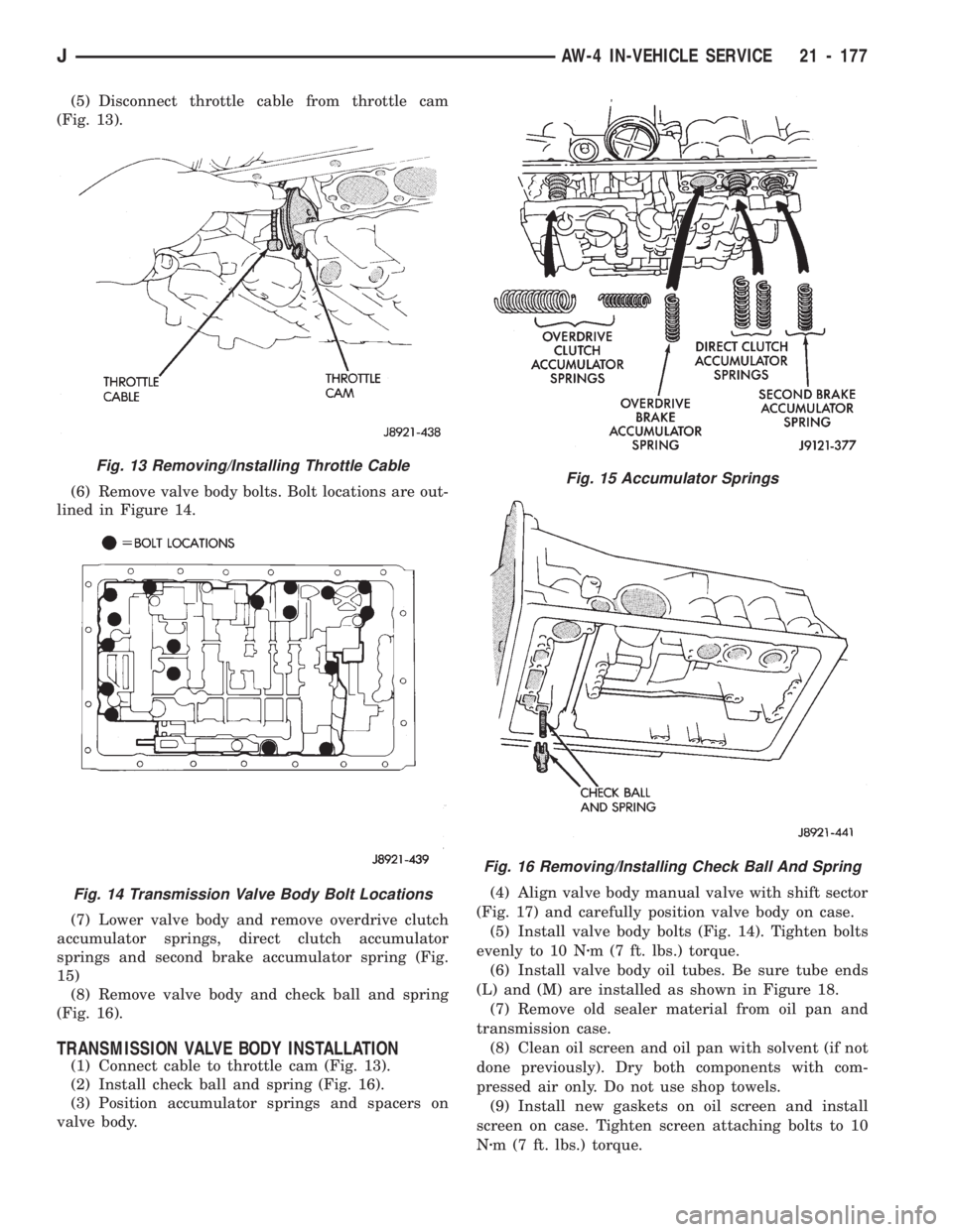
(5) Disconnect throttle cable from throttle cam
(Fig. 13).
(6) Remove valve body bolts. Bolt locations are out-
lined in Figure 14.
(7) Lower valve body and remove overdrive clutch
accumulator springs, direct clutch accumulator
springs and second brake accumulator spring (Fig.
15)
(8) Remove valve body and check ball and spring
(Fig. 16).
TRANSMISSION VALVE BODY INSTALLATION
(1) Connect cable to throttle cam (Fig. 13).
(2) Install check ball and spring (Fig. 16).
(3) Position accumulator springs and spacers on
valve body.(4) Align valve body manual valve with shift sector
(Fig. 17) and carefully position valve body on case.
(5) Install valve body bolts (Fig. 14). Tighten bolts
evenly to 10 Nzm (7 ft. lbs.) torque.
(6) Install valve body oil tubes. Be sure tube ends
(L) and (M) are installed as shown in Figure 18.
(7) Remove old sealer material from oil pan and
transmission case.
(8) Clean oil screen and oil pan with solvent (if not
done previously). Dry both components with com-
pressed air only. Do not use shop towels.
(9) Install new gaskets on oil screen and install
screen on case. Tighten screen attaching bolts to 10
Nzm (7 ft. lbs.) torque.
Fig. 13 Removing/Installing Throttle Cable
Fig. 14 Transmission Valve Body Bolt Locations
Fig. 15 Accumulator Springs
Fig. 16 Removing/Installing Check Ball And Spring
JAW-4 IN-VEHICLE SERVICE 21 - 177