Page 1361 of 1784
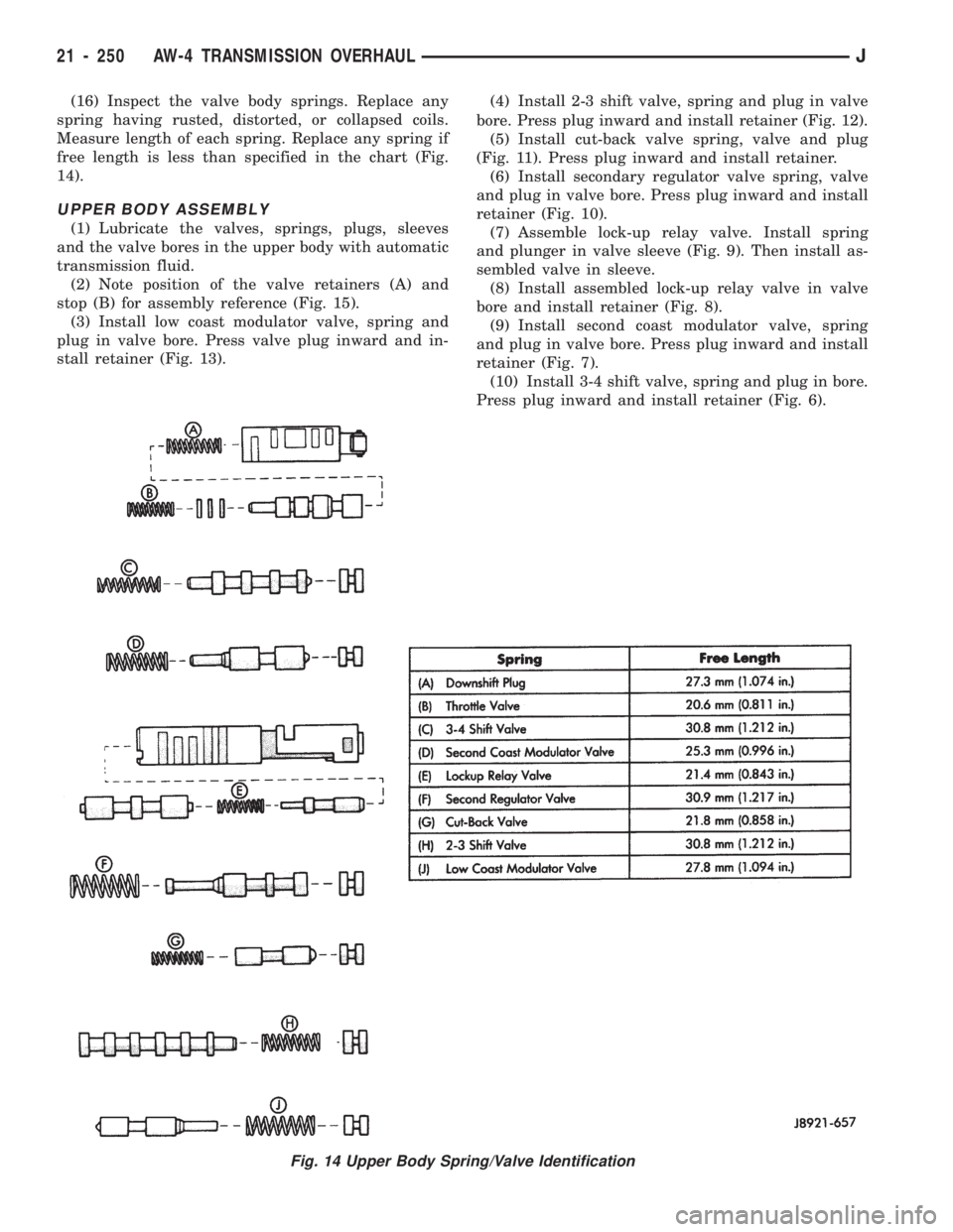
(16) Inspect the valve body springs. Replace any
spring having rusted, distorted, or collapsed coils.
Measure length of each spring. Replace any spring if
free length is less than specified in the chart (Fig.
14).
UPPER BODY ASSEMBLY
(1) Lubricate the valves, springs, plugs, sleeves
and the valve bores in the upper body with automatic
transmission fluid.
(2) Note position of the valve retainers (A) and
stop (B) for assembly reference (Fig. 15).
(3) Install low coast modulator valve, spring and
plug in valve bore. Press valve plug inward and in-
stall retainer (Fig. 13).(4) Install 2-3 shift valve, spring and plug in valve
bore. Press plug inward and install retainer (Fig. 12).
(5) Install cut-back valve spring, valve and plug
(Fig. 11). Press plug inward and install retainer.
(6) Install secondary regulator valve spring, valve
and plug in valve bore. Press plug inward and install
retainer (Fig. 10).
(7) Assemble lock-up relay valve. Install spring
and plunger in valve sleeve (Fig. 9). Then install as-
sembled valve in sleeve.
(8) Install assembled lock-up relay valve in valve
bore and install retainer (Fig. 8).
(9) Install second coast modulator valve, spring
and plug in valve bore. Press plug inward and install
retainer (Fig. 7).
(10) Install 3-4 shift valve, spring and plug in bore.
Press plug inward and install retainer (Fig. 6).
Fig. 14 Upper Body Spring/Valve Identification
21 - 250 AW-4 TRANSMISSION OVERHAULJ
Page 1363 of 1784
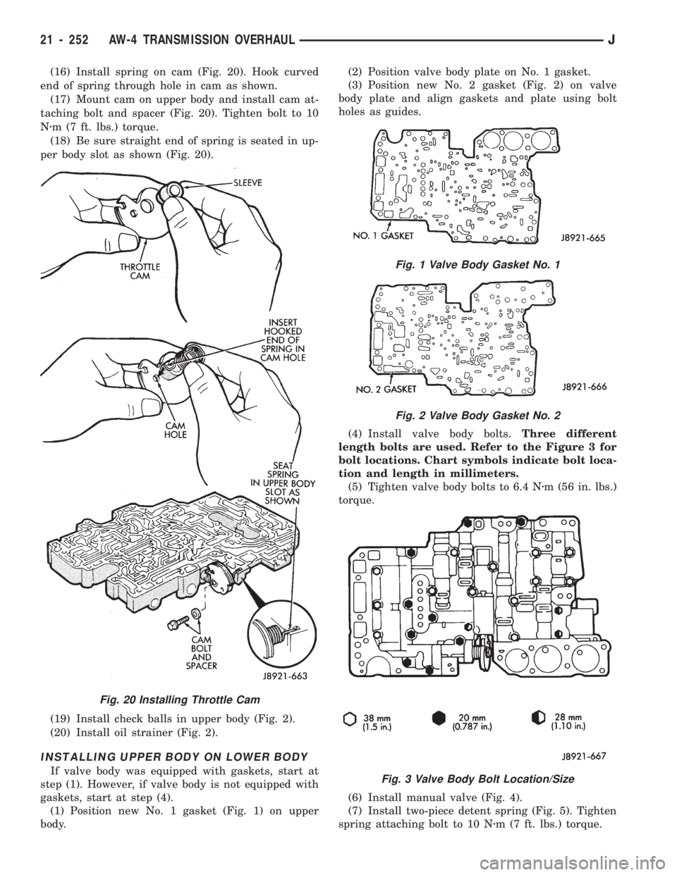
(16) Install spring on cam (Fig. 20). Hook curved
end of spring through hole in cam as shown.
(17) Mount cam on upper body and install cam at-
taching bolt and spacer (Fig. 20). Tighten bolt to 10
Nzm (7 ft. lbs.) torque.
(18) Be sure straight end of spring is seated in up-
per body slot as shown (Fig. 20).
(19) Install check balls in upper body (Fig. 2).
(20) Install oil strainer (Fig. 2).
INSTALLING UPPER BODY ON LOWER BODY
If valve body was equipped with gaskets, start at
step (1). However, if valve body is not equipped with
gaskets, start at step (4).
(1) Position new No. 1 gasket (Fig. 1) on upper
body.(2) Position valve body plate on No. 1 gasket.
(3) Position new No. 2 gasket (Fig. 2) on valve
body plate and align gaskets and plate using bolt
holes as guides.
(4) Install valve body bolts.Three different
length bolts are used. Refer to the Figure 3 for
bolt locations. Chart symbols indicate bolt loca-
tion and length in millimeters.
(5) Tighten valve body bolts to 6.4 Nzm (56 in. lbs.)
torque.
(6) Install manual valve (Fig. 4).
(7) Install two-piece detent spring (Fig. 5). Tighten
spring attaching bolt to 10 Nzm (7 ft. lbs.) torque.
Fig. 20 Installing Throttle Cam
Fig. 1 Valve Body Gasket No. 1
Fig. 2 Valve Body Gasket No. 2
Fig. 3 Valve Body Bolt Location/Size
21 - 252 AW-4 TRANSMISSION OVERHAULJ
Page 1377 of 1784
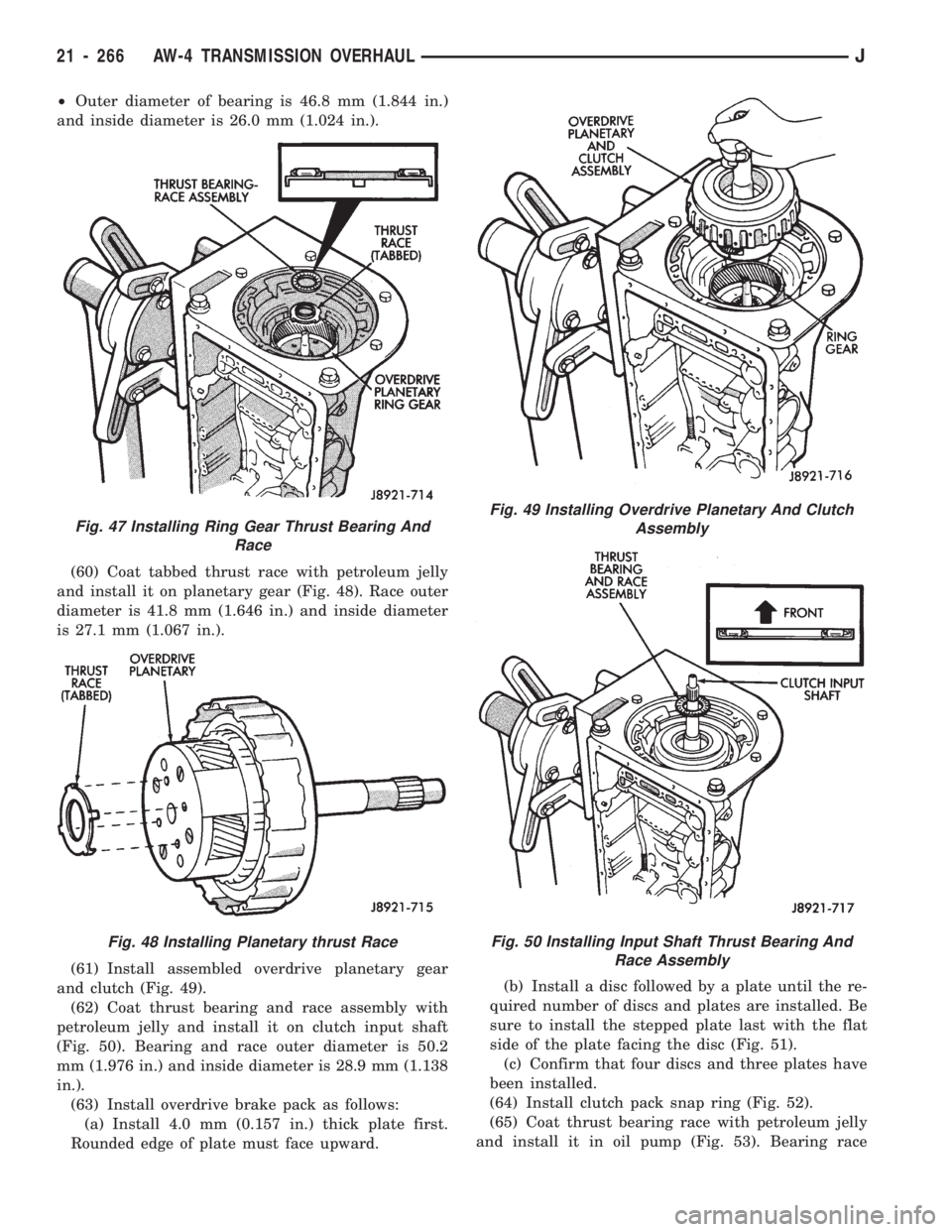
²Outer diameter of bearing is 46.8 mm (1.844 in.)
and inside diameter is 26.0 mm (1.024 in.).
(60) Coat tabbed thrust race with petroleum jelly
and install it on planetary gear (Fig. 48). Race outer
diameter is 41.8 mm (1.646 in.) and inside diameter
is 27.1 mm (1.067 in.).
(61) Install assembled overdrive planetary gear
and clutch (Fig. 49).
(62) Coat thrust bearing and race assembly with
petroleum jelly and install it on clutch input shaft
(Fig. 50). Bearing and race outer diameter is 50.2
mm (1.976 in.) and inside diameter is 28.9 mm (1.138
in.).
(63) Install overdrive brake pack as follows:
(a) Install 4.0 mm (0.157 in.) thick plate first.
Rounded edge of plate must face upward.(b) Install a disc followed by a plate until the re-
quired number of discs and plates are installed. Be
sure to install the stepped plate last with the flat
side of the plate facing the disc (Fig. 51).
(c) Confirm that four discs and three plates have
been installed.
(64) Install clutch pack snap ring (Fig. 52).
(65) Coat thrust bearing race with petroleum jelly
and install it in oil pump (Fig. 53). Bearing race
Fig. 47 Installing Ring Gear Thrust Bearing And
Race
Fig. 48 Installing Planetary thrust Race
Fig. 49 Installing Overdrive Planetary And Clutch
Assembly
Fig. 50 Installing Input Shaft Thrust Bearing And
Race Assembly
21 - 266 AW-4 TRANSMISSION OVERHAULJ
Page 1378 of 1784
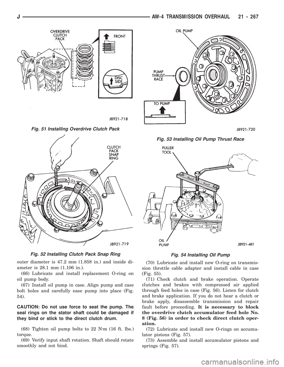
outer diameter is 47.2 mm (1.858 in.) and inside di-
ameter is 28.1 mm (1.106 in.).
(66) Lubricate and install replacement O-ring on
oil pump body.
(67) Install oil pump in case. Align pump and case
bolt holes and carefully ease pump into place (Fig.
54).
CAUTION: Do not use force to seat the pump. The
seal rings on the stator shaft could be damaged if
they bind or stick to the direct clutch drum.
(68) Tighten oil pump bolts to 22 Nzm (16 ft. lbs.)
torque.
(69) Verify input shaft rotation. Shaft should rotate
smoothly and not bind.(70) Lubricate and install new O-ring on transmis-
sion throttle cable adapter and install cable in case
(Fig. 55).
(71) Check clutch and brake operation. Operate
clutches and brakes with compressed air applied
through feed holes in case (Fig. 56). Listen for clutch
and brake application. If you do not hear a clutch or
brake apply, disassemble transmission and repair
fault before proceeding.It is necessary to block
the overdrive clutch accumulator feed hole No.
8 (Fig. 56) in order to check direct clutch oper-
ation.
(72) Lubricate and install new O-rings on accumu-
lator pistons (Fig. 57).
(73) Assemble and install accumulator pistons and
springs (Fig. 57).
Fig. 53 Installing Oil Pump Thrust Race
Fig. 54 Installing Oil Pump
Fig. 51 Installing Overdrive Clutch Pack
Fig. 52 Installing Clutch Pack Snap Ring
JAW-4 TRANSMISSION OVERHAUL 21 - 267
Page 1380 of 1784
(82) Install valve body oil tubes (Fig. 62). Tap
tubes into place with a plastic mallet. Be sure the
flanged tube ends and straight tube ends are in-
stalled as shown.
(83) Install new gaskets on oil screen and install
screen on valve body. Tighten screen bolts to 10 Nzm
(7 ft. lbs.) torque.
(84) Install magnet in oil pan. Be sure magnet
does not interfere with valve body oil tubes.
(85) Apply Mopar or Loctite 599 to sealing surface
of oil pan. Sealer bead should be at least 3 mm (1/8
in.) wide. Install pan on case and tighten pan bolts to
7Nzm (65 in. lbs.) torque.
(86) Install transmission speed sensor rotor and
key on output shaft (Fig. 63).
Fig. 63 Installing Transmission Speed Sensor Rotor
And Key
Fig. 61 Connecting Valve Body Solenoid Wires
Fig. 62 Installing Valve Body Oil Tubes
Fig. 59 Aligning Manual Valve, Shift Sector And
Detent Spring
Fig. 60 Connecting Transmission Throttle Cable
JAW-4 TRANSMISSION OVERHAUL 21 - 269
Page 1389 of 1784
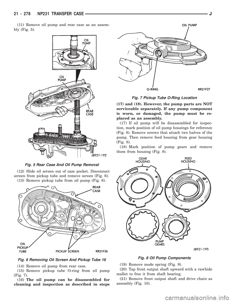
(11) Remove oil pump and rear case as an assem-
bly (Fig. 5).
(12) Slide oil screen out of case pocket. Disconnect
screen from pickup tube and remove screen (Fig. 6).
(13) Remove pickup tube from oil pump (Fig. 6).
(14) Remove oil pump from rear case.
(15) Remove pickup tube O-ring from oil pump
(Fig. 7).
(16)The oil pump can be disassembled for
cleaning and inspection as described in steps(17) and (18). However, the pump parts are NOT
serviceable separately. If any pump component
is worn, or damaged, the pump must be re-
placed as an assembly.
(17) If oil pump will be disassembled for inspec-
tion, mark position of oil pump housings for reference
(Fig. 8). Remove screws that attach two halves of the
pump. Then remove feed housing from gear housing
(Fig. 8).
(18) Mark position of pump gears and remove
them from housing (Fig. 8).
(19) Remove mode spring (Fig. 9).
(20) Tap front output shaft upward with a rawhide
mallet to free it from shaft bearing.
(21) Remove front output shaft and drive chain as
assembly (Fig. 10).
Fig. 5 Rear Case And Oil Pump Removal
Fig. 6 Removing Oil Screen And Pickup Tube 16
Fig. 7 Pickup Tube O-Ring Location
Fig. 8 Oil Pump Components
21 - 278 NP231 TRANSFER CASEJ
Page 1392 of 1784
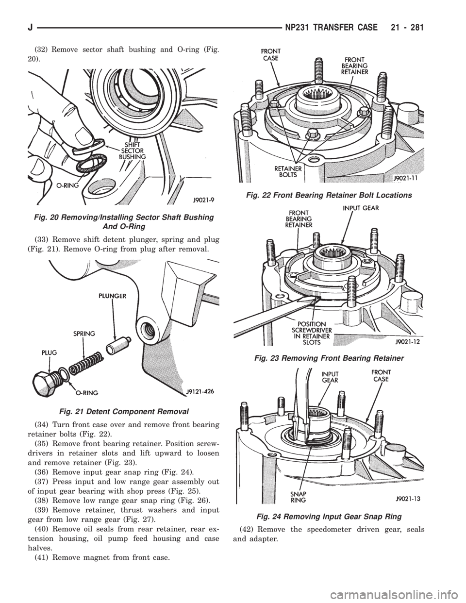
(32) Remove sector shaft bushing and O-ring (Fig.
20).
(33) Remove shift detent plunger, spring and plug
(Fig. 21). Remove O-ring from plug after removal.
(34) Turn front case over and remove front bearing
retainer bolts (Fig. 22).
(35) Remove front bearing retainer. Position screw-
drivers in retainer slots and lift upward to loosen
and remove retainer (Fig. 23).
(36) Remove input gear snap ring (Fig. 24).
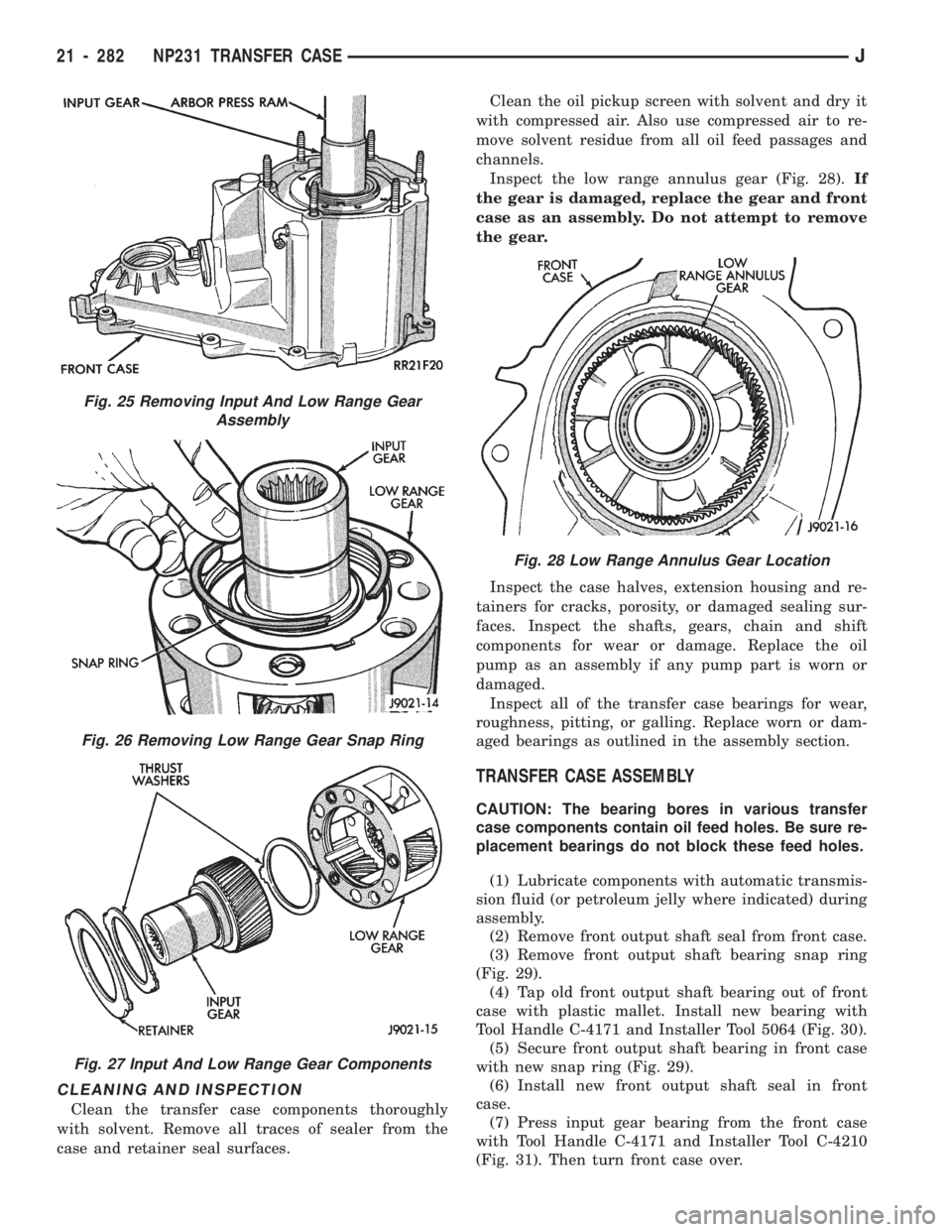
(37) Press input and low range gear assembly out
of input gear bearing with shop press (Fig. 25).
(38) Remove low range gear snap ring (Fig. 26).
(39) Remove retainer, thrust washers and input
gear from low range gear (Fig. 27).
(40) Remove oil seals from rear retainer, rear ex-
tension housing, oil pump feed housing and case
halves.
(41) Remove magnet from front case.(42) Remove the speedometer driven gear, seals
and adapter.
Fig. 20 Removing/Installing Sector Shaft Bushing
And O-Ring
Fig. 21 Detent Component Removal
Fig. 22 Front Bearing Retainer Bolt Locations
Fig. 23 Removing Front Bearing Retainer
Fig. 24 Removing Input Gear Snap Ring
JNP231 TRANSFER CASE 21 - 281
Page 1393 of 1784
CLEANING AND INSPECTION
Clean the transfer case components thoroughly
with solvent. Remove all traces of sealer from the
case and retainer seal surfaces.Clean the oil pickup screen with solvent and dry it
with compressed air. Also use compressed air to re-
move solvent residue from all oil feed passages and
channels.
Inspect the low range annulus gear (Fig. 28).If
the gear is damaged, replace the gear and front
case as an assembly. Do not attempt to remove
the gear.
Inspect the case halves, extension housing and re-
tainers for cracks, porosity, or damaged sealing sur-
faces. Inspect the shafts, gears, chain and shift
components for wear or damage. Replace the oil
pump as an assembly if any pump part is worn or
damaged.
Inspect all of the transfer case bearings for wear,
roughness, pitting, or galling. Replace worn or dam-
aged bearings as outlined in the assembly section.
TRANSFER CASE ASSEMBLY
CAUTION: The bearing bores in various transfer
case components contain oil feed holes. Be sure re-
placement bearings do not block these feed holes.
(1) Lubricate components with automatic transmis-
sion fluid (or petroleum jelly where indicated) during
assembly.
(2) Remove front output shaft seal from front case.
(3) Remove front output shaft bearing snap ring
(Fig. 29).
(4) Tap old front output shaft bearing out of front
case with plastic mallet. Install new bearing with
Tool Handle C-4171 and Installer Tool 5064 (Fig. 30).
(5) Secure front output shaft bearing in front case
with new snap ring (Fig. 29).
(6) Install new front output shaft seal in front
case.
(7) Press input gear bearing from the front case
with Tool Handle C-4171 and Installer Tool C-4210
(Fig. 31). Then turn front case over.
Fig. 25 Removing Input And Low Range Gear
Assembly
Fig. 26 Removing Low Range Gear Snap Ring
Fig. 27 Input And Low Range Gear Components
Fig. 28 Low Range Annulus Gear Location
21 - 282 NP231 TRANSFER CASEJ