1994 JEEP CHEROKEE oil
[x] Cancel search: oilPage 1679 of 1784
²Battery side of fuse No.12 should be battery volt-
age. If not, repair open from ignition switch.
²A/C blower switch (terminal A) should be battery
voltage. If not, repair open from fuse No.12.
2. BLOWER SWITCHÐIgnition in RUN.
²A/C blower switch (Terminal A) with blower
switch in any position should be battery voltage. If
not, repair open from fuse panel.
²A/C blower switch (Terminal L) with blower
switch in LO should be battery voltage. If not, re-
place switch.
²A/C blower switch (Terminal M) with blower
switch in MED should be battery voltage. If not, re-
place switch.
²A/C blower switch (Terminal H) with blower
switch in HI should be battery voltage. If not, replace
switch.
3. BLOWER MOTOR
Turn ignition switch to RUN for voltage tests and
turn ignition switch to OFF for resistance tests.
²A/C blower housing to ground (Terminal G) should
be 0 ohms. If not, repair ground connection. If the
blower motor is still inoperative, replace motor.
²A/C blower motor connector (Terminal C) with
blower switch in LO should be battery voltage. If not,
repair open from blower switch. If the blower motor
is still inoperative, replace motor.
²A/C blower motor connector (Terminal B) with
blower switch in MED should be battery voltage. If
not, repair open from blower switch. If the blower
motor is still inoperative, replace motor.
²A/C blower motor connector (Terminal A) with
blower switch in HI should be battery voltage. If not,
repair open from blower switch. If the blower motor
is still inoperative, replace motor.COMPRESSOR CLUTCH
Refer to Group 8W, Wiring Diagrams for complete
system schematic.
With engine running, Engine Controller may delay
A/C clutch up to 30 seconds.
1. COMPRESSOR CLUTCH.
²Jumper wire from battery positive post to A/C
compressor clutch connector (Terminal A), clutch
should engage. If not, go to next step with jumper in-
stalled.
²Jumper wire from clutch coil frame to chassis
ground, clutch should engage. If not, repair clutch
coil ground or replace coil.
2. LOW PRESSURE SWITCH
Turn ignition switch to RUN, A/C blower switch to
ON and thermostatic control set to MAX cool.
²A/C low pressure switch connector (Terminal A)
should be battery voltage. If not, proceed to thermo-
static control tests (Step 3).
²Jumper wire across A/C low pressure switch con-
nector (Terminals A and B), clutch should engage. If
not, check system refrigerant charge. If system is
properly charged, replace A/C low pressure switch.
3. THERMOSTATIC CONTROL
Turn ignition switch to RUN, A/C blower switch to
ON and thermostatic control set to MAX cool.
²Thermostatic control connector (Terminal A)
should be battery voltage. If not, repair open from
blower switch.
²Thermostatic control connector (Terminal B)
should be battery voltage. If not, replace thermo-
static control.
²A/C low pressure switch connector (Terminal A)
should be battery voltage. If not, repair open from
thermostatic control.
24 - 16 HEATING AND AIR CONDITIONINGJ
Page 1680 of 1784
COMPRESSOR OVERHAUL
INDEX
page page
Compressor............................. 17
Compressor Isolation...................... 17
Description............................. 17Magnetic Clutch......................... 18
Purging Compressor of Air................. 17
DESCRIPTION
The A/C system uses a Sanden compressor. This
compressor is a 7 piston design. Designated the SD-
709, the compressor is mounted on the front right
side of the engine and is driven by a serpentine belt.
System lubrication is provided by 135cc615cc (4.6
cu. in.60.5 cu. in.) of 500 viscosity refrigerant oil.
The clutch used on the compressor consists of 3 ba-
sic components: the pulley, front plate and the field
coil. The pulley and field coil are attached to the
front head of the compressor with tapered snap rings.
The hub is keyed to the compressor shaft and is re-
tained on the shaft with a self-locking nut. Special
service tools are required to remove and install the
clutch plate on the compressor shaft.
COMPRESSOR ISOLATION
It is not necessary to discharge the system for com-
pressor removal. The compressor can be isolated from
the remainder of the system and eliminate the need
for recharging when performing compressor service.
(1) Connect pressure gauge and manifold.
(2) Close both gauge hand valves.
(3) Mid-position both service valves.
WARNING: USE EXTREME CAUTION WHEN THE
ENGINE IS OPERATING. DO NOT STAND IN A DI-
RECT LINE WITH THE FAN. DO NOT PUT YOUR
HANDS NEAR THE PULLEYS, BELTS OR FAN. DO
NOT WEAR LOOSE CLOTHING.
(4) Start the engine and operate the air condition-
ing system.
(5) Turn the suction service valve slowly clockwise
toward the front seated position.
(6) When pressure drops to zero, stop the engine
and compressor and quickly finish front-seating the
suction service valve.
(7) Front-seat the discharge service valve.
(8) Loosen the oil level check plug slowly to re-
lease any internal pressure in the compressor.
The compressor is now isolated from the remainder
of the system.
The service valves can be removed from the com-
pressor.
PURGING COMPRESSOR OF AIR
The compressor must be purged of air whenever it
has been isolated for an oil level check or other ser-
vice procedures without discharging the entire sys-
tem.
(1) Cap the service gauge ports on both of the ser-
vice valves.
(2) Back-seat the suction service valve to allow the
system refrigerant to enter the compressor.
(3) Place the discharge service valve in the mid-po-
sition or cracked-position.
(4) Loosen the discharge service valve gauge port
cap to permit the refrigerant to force any air out of
the compressor.
(5) Back-seat the discharge service valve and
tighten the gauge port cap.
(6) The compressor is now ready for service.
COMPRESSOR
REMOVAL
(1) Isolate the compressor.
(2) Disconnect negative cable from battery.
(3) Disconnect the clutch lead wire.
(4) Remove the discharge and inlet (suction) ser-
vice valves from the compressor. Plug or tape all the
openings.
(5) Remove the serpentine drive belt (refer to
Group 7, Cooling System for the proper procedure).
(6) Remove the bolts and lift the compressor from
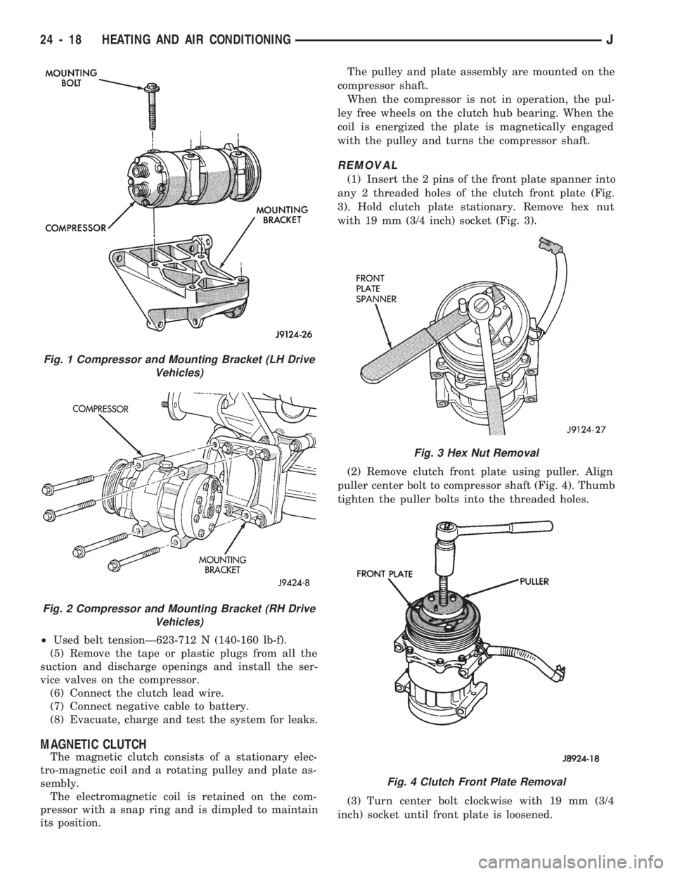
the mounting bracket (Figs. 1 and 2).
INSTALLATION
If a replacement compressor is being installed;
check the oil level. Add or subtract oil as neces-
sary and install the magnetic clutch on the com-
pressor.
(1) If the mounting bracket was removed, install
the bracket to the block. Tighten the mounting bolts
to 27 NIm (20 ft. lbs.) torque.
(2) Install the compressor on the mounting
bracket. Tighten the bolts to 27 NIm (20 ft. lbs.)
torque.
(3) Install the serpentine drive belt (refer to Group
7, Cooling System for the proper procedure).
(4) Tighten the serpentine drive belt to the speci-
fied tension.
²New belt tensionÐ800-900 N (180-200 lb-f).
JHEATING AND AIR CONDITIONING 24 - 17
Page 1681 of 1784
²Used belt tensionÐ623-712 N (140-160 lb-f).
(5) Remove the tape or plastic plugs from all the
suction and discharge openings and install the ser-
vice valves on the compressor.
(6) Connect the clutch lead wire.
(7) Connect negative cable to battery.
(8) Evacuate, charge and test the system for leaks.
MAGNETIC CLUTCH
The magnetic clutch consists of a stationary elec-
tro-magnetic coil and a rotating pulley and plate as-
sembly.
The electromagnetic coil is retained on the com-
pressor with a snap ring and is dimpled to maintain
its position.The pulley and plate assembly are mounted on the
compressor shaft.
When the compressor is not in operation, the pul-
ley free wheels on the clutch hub bearing. When the
coil is energized the plate is magnetically engaged
with the pulley and turns the compressor shaft.
REMOVAL
(1) Insert the 2 pins of the front plate spanner into
any 2 threaded holes of the clutch front plate (Fig.
3). Hold clutch plate stationary. Remove hex nut
with 19 mm (3/4 inch) socket (Fig. 3).
(2) Remove clutch front plate using puller. Align
puller center bolt to compressor shaft (Fig. 4). Thumb
tighten the puller bolts into the threaded holes.
(3) Turn center bolt clockwise with 19 mm (3/4
inch) socket until front plate is loosened.
Fig. 1 Compressor and Mounting Bracket (LH Drive
Vehicles)
Fig. 2 Compressor and Mounting Bracket (RH Drive
Vehicles)
Fig. 3 Hex Nut Removal
Fig. 4 Clutch Front Plate Removal
24 - 18 HEATING AND AIR CONDITIONINGJ
Page 1682 of 1784
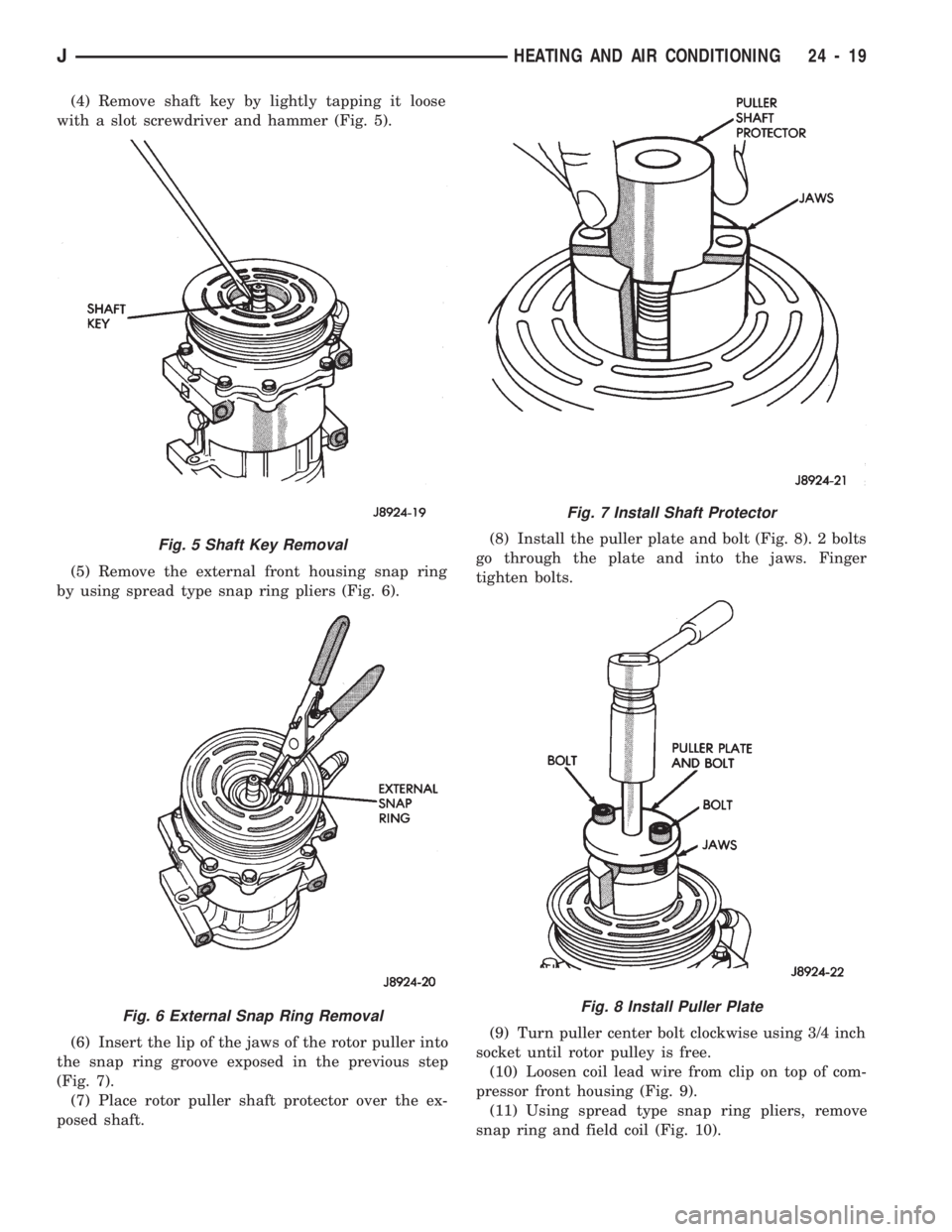
(4) Remove shaft key by lightly tapping it loose
with a slot screwdriver and hammer (Fig. 5).
(5) Remove the external front housing snap ring
by using spread type snap ring pliers (Fig. 6).
(6) Insert the lip of the jaws of the rotor puller into
the snap ring groove exposed in the previous step
(Fig. 7).
(7) Place rotor puller shaft protector over the ex-
posed shaft.(8) Install the puller plate and bolt (Fig. 8). 2 bolts
go through the plate and into the jaws. Finger
tighten bolts.
(9) Turn puller center bolt clockwise using 3/4 inch
socket until rotor pulley is free.
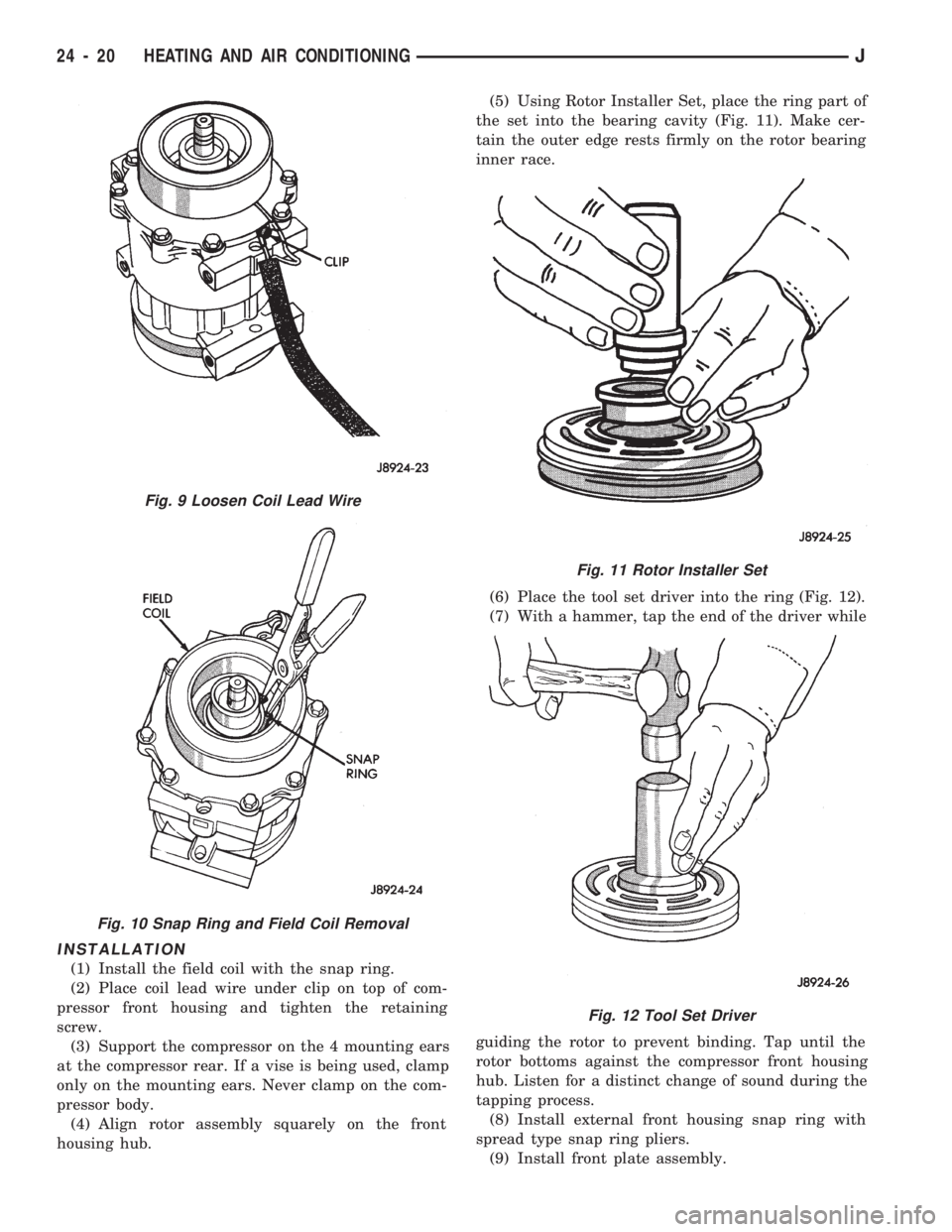
(10) Loosen coil lead wire from clip on top of com-
pressor front housing (Fig. 9).
(11) Using spread type snap ring pliers, remove
snap ring and field coil (Fig. 10).
Fig. 5 Shaft Key Removal
Fig. 6 External Snap Ring Removal
Fig. 7 Install Shaft Protector
Fig. 8 Install Puller Plate
JHEATING AND AIR CONDITIONING 24 - 19
Page 1683 of 1784
INSTALLATION
(1) Install the field coil with the snap ring.
(2) Place coil lead wire under clip on top of com-
pressor front housing and tighten the retaining
screw.
(3) Support the compressor on the 4 mounting ears
at the compressor rear. If a vise is being used, clamp
only on the mounting ears. Never clamp on the com-
pressor body.
(4) Align rotor assembly squarely on the front
housing hub.(5) Using Rotor Installer Set, place the ring part of
the set into the bearing cavity (Fig. 11). Make cer-
tain the outer edge rests firmly on the rotor bearing
inner race.
(6) Place the tool set driver into the ring (Fig. 12).
(7) With a hammer, tap the end of the driver while
guiding the rotor to prevent binding. Tap until the
rotor bottoms against the compressor front housing
hub. Listen for a distinct change of sound during the
tapping process.
(8) Install external front housing snap ring with
spread type snap ring pliers.
(9) Install front plate assembly.
Fig. 9 Loosen Coil Lead Wire
Fig. 10 Snap Ring and Field Coil Removal
Fig. 11 Rotor Installer Set
Fig. 12 Tool Set Driver
24 - 20 HEATING AND AIR CONDITIONINGJ
Page 1685 of 1784
CLIMATE CONTROL SYSTEMÐXJ VEHICLES
INDEX
page page
A/C Recirculating Air Door Vacuum Motor
Replacement.......................... 31
Blower Motor Resistors Replacement......... 35
Blower Motor/Fan Replacement.............. 26
CondenserÐ4.0L Engines.................. 32
Condenser/Receiver DrierÐ2.5L Engines....... 31
Defroster Duct Replacement................ 29
Description............................. 22
Evaporator Coil.......................... 34
Evaporator/Blower Housing................. 33Expansion (H) Valve...................... 35
Heater and A/C Control Panel Replacement.... 26
Heater Control Cable Replacement........... 30
Heater Core............................ 28
Heater Core Housing Replacement........... 29
Heater/Defroster/Instrument Panel Outlet Door
Vacuum Motor Replacement............... 30
Receiver DrierÐ4.0L Engines............... 32
Temperature Control Thermostat............. 35
DESCRIPTION
The Climate Control System combines air condi-
tioning, heating and ventilating capabilities for vehi-
cles equipped with air conditioning. Vehicles without
air conditioning perform heating and ventilating
functions without the air conditioning evaporator.
Both systems consist basically of 2 parts:
²Blower and Air Inlet Assembly
²Heater Core and Air Distribution Assembly
These assemblies, initially installed as a single
unit, may be removed separately from under the in-
strument panel as required for service.
HEATER SYSTEM
The heater system is a blend air type. Outside air
is heated and then blended in varying amounts with
cooler outside air to obtain the desired discharge
temperature. A heater coolant valve provides full
flow to the heater core for all heating modes. The
heater coolant valve remains closed for the ventila-
tion mode, allowing discharge air to approach the
outside ambient air temperature.
AIR CONDITIONING SYSTEM
The air conditioning system has an evaporator to
cool and dehumidify the incoming outside air prior to
blending with the heated air. The evaporator is in
operation during the A/C mode and also in the de-
frost mode for defogging purposes. The evaporator is
not in operation at ambient temperatures below ap-
proximately -1ÉC (30ÉF). To maintain minimum evap-
orator temperature, a fixed thermostat setting switch
cycles the compressor clutch. The blower is operatingthe heater or air conditioning systems, except the
OFF mode. In this mode (OFF) the blower and the
outside air are shut off.
The cooling unit is mounted on the dash panel and
the cooled air is discharged from the instrument
panel registers. The registers are adjusted to provide
general or localized cooling.
SIGHT GLASS
The sight glass is located on top of the receiver/
drier. The sight glass provides a visual check of the
system refrigerant level. A continuous stream of bub-
bles will appear in the sight glass when the system
charge is low. Bubbles will not appear when the sys-
tem is fully charged.
LOW PRESSURE SWITCH
The low pressure switch disengages the magnetic
clutch if the pressure in the system drops below 193
kPa (28 psi). This will occur with a loss in refriger-
ant or with cold ambient temperature.
HEATER VALVE
The heater valve regulates coolant flow to the
heater core. It requires vacuum to shut off flow to
the heater core.
These vehicles are equipped with a bypass-type
heater water valve. When the heater valve is closed,
coolant flow to the heater core is bypassed back to
the engine. When the heater valve is open, coolant is
directed through the heater core and back to the en-
gine.
24 - 22 HEATING AND AIR CONDITIONINGJ
Page 1695 of 1784
INSTALLATION
(1) Remove the plugs from the receiver/drier open-
ings. Install receiver/drier into the condenser.
(2) Install the condenser to the radiator. Tighten
the retaining bolts.
(3) Install the radiator and condenser as an assem-
bly (refer to Group 7, Cooling System for the proper
procedure).
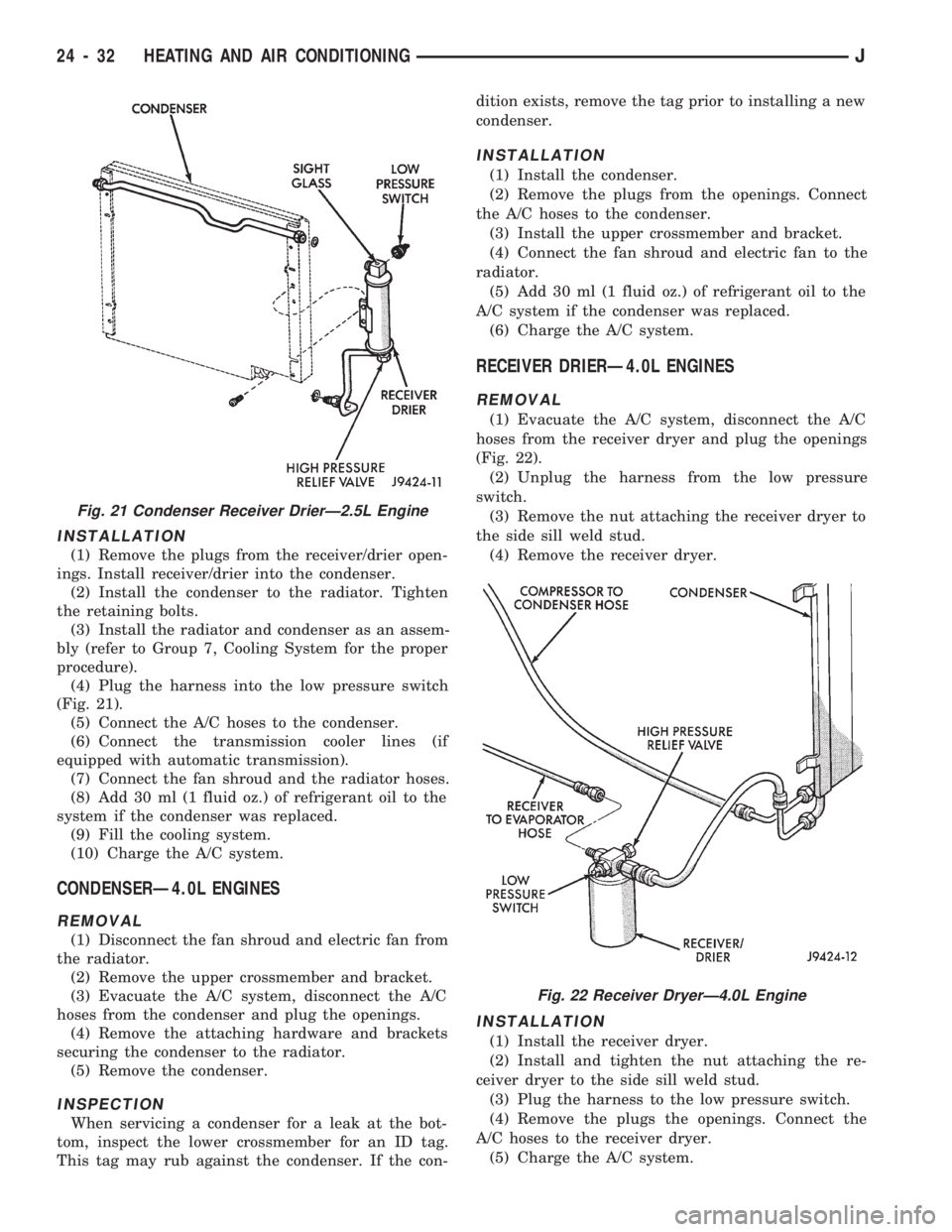
(4) Plug the harness into the low pressure switch
(Fig. 21).
(5) Connect the A/C hoses to the condenser.
(6) Connect the transmission cooler lines (if
equipped with automatic transmission).
(7) Connect the fan shroud and the radiator hoses.
(8) Add 30 ml (1 fluid oz.) of refrigerant oil to the
system if the condenser was replaced.
(9) Fill the cooling system.
(10) Charge the A/C system.
CONDENSERÐ4.0L ENGINES
REMOVAL
(1) Disconnect the fan shroud and electric fan from
the radiator.
(2) Remove the upper crossmember and bracket.
(3) Evacuate the A/C system, disconnect the A/C
hoses from the condenser and plug the openings.
(4) Remove the attaching hardware and brackets
securing the condenser to the radiator.
(5) Remove the condenser.
INSPECTION
When servicing a condenser for a leak at the bot-
tom, inspect the lower crossmember for an ID tag.
This tag may rub against the condenser. If the con-dition exists, remove the tag prior to installing a new
condenser.
INSTALLATION
(1) Install the condenser.
(2) Remove the plugs from the openings. Connect
the A/C hoses to the condenser.
(3) Install the upper crossmember and bracket.
(4) Connect the fan shroud and electric fan to the
radiator.
(5) Add 30 ml (1 fluid oz.) of refrigerant oil to the
A/C system if the condenser was replaced.
(6) Charge the A/C system.
RECEIVER DRIERÐ4.0L ENGINES
REMOVAL
(1) Evacuate the A/C system, disconnect the A/C
hoses from the receiver dryer and plug the openings
(Fig. 22).
(2) Unplug the harness from the low pressure
switch.
(3) Remove the nut attaching the receiver dryer to
the side sill weld stud.
(4) Remove the receiver dryer.
INSTALLATION
(1) Install the receiver dryer.
(2) Install and tighten the nut attaching the re-
ceiver dryer to the side sill weld stud.
(3) Plug the harness to the low pressure switch.
(4) Remove the plugs the openings. Connect the
A/C hoses to the receiver dryer.
(5) Charge the A/C system.
Fig. 21 Condenser Receiver DrierÐ2.5L Engine
Fig. 22 Receiver DryerÐ4.0L Engine
24 - 32 HEATING AND AIR CONDITIONINGJ
Page 1697 of 1784
INSTALLATION
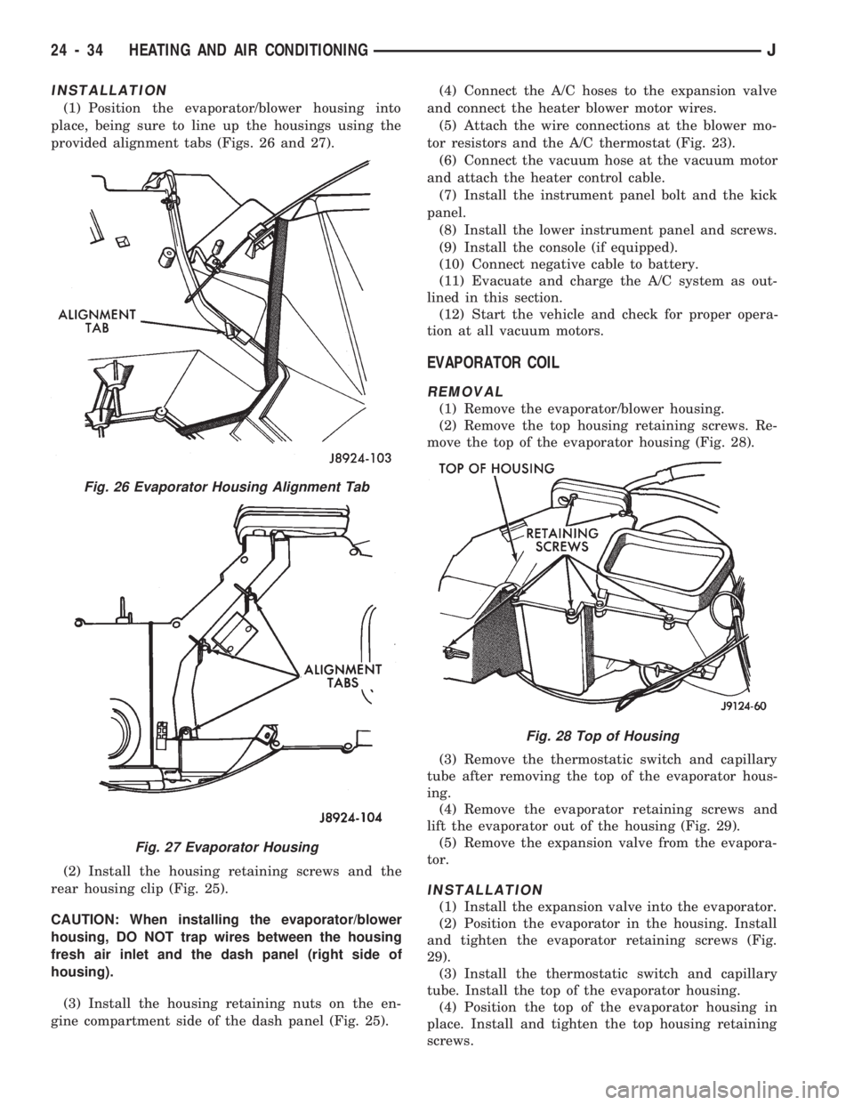
(1) Position the evaporator/blower housing into
place, being sure to line up the housings using the
provided alignment tabs (Figs. 26 and 27).
(2) Install the housing retaining screws and the
rear housing clip (Fig. 25).
CAUTION: When installing the evaporator/blower
housing, DO NOT trap wires between the housing
fresh air inlet and the dash panel (right side of
housing).
(3) Install the housing retaining nuts on the en-
gine compartment side of the dash panel (Fig. 25).(4) Connect the A/C hoses to the expansion valve
and connect the heater blower motor wires.
(5) Attach the wire connections at the blower mo-
tor resistors and the A/C thermostat (Fig. 23).
(6) Connect the vacuum hose at the vacuum motor
and attach the heater control cable.
(7) Install the instrument panel bolt and the kick
panel.
(8) Install the lower instrument panel and screws.
(9) Install the console (if equipped).
(10) Connect negative cable to battery.
(11) Evacuate and charge the A/C system as out-
lined in this section.
(12) Start the vehicle and check for proper opera-
tion at all vacuum motors.
EVAPORATOR COIL
REMOVAL
(1) Remove the evaporator/blower housing.
(2) Remove the top housing retaining screws. Re-
move the top of the evaporator housing (Fig. 28).
(3) Remove the thermostatic switch and capillary
tube after removing the top of the evaporator hous-
ing.
(4) Remove the evaporator retaining screws and
lift the evaporator out of the housing (Fig. 29).
(5) Remove the expansion valve from the evapora-
tor.
INSTALLATION
(1) Install the expansion valve into the evaporator.
(2) Position the evaporator in the housing. Install
and tighten the evaporator retaining screws (Fig.
29).
(3) Install the thermostatic switch and capillary
tube. Install the top of the evaporator housing.
(4) Position the top of the evaporator housing in
place. Install and tighten the top housing retaining
screws.
Fig. 26 Evaporator Housing Alignment Tab
Fig. 27 Evaporator Housing
Fig. 28 Top of Housing
24 - 34 HEATING AND AIR CONDITIONINGJ