1994 JEEP CHEROKEE oil
[x] Cancel search: oilPage 1425 of 1784
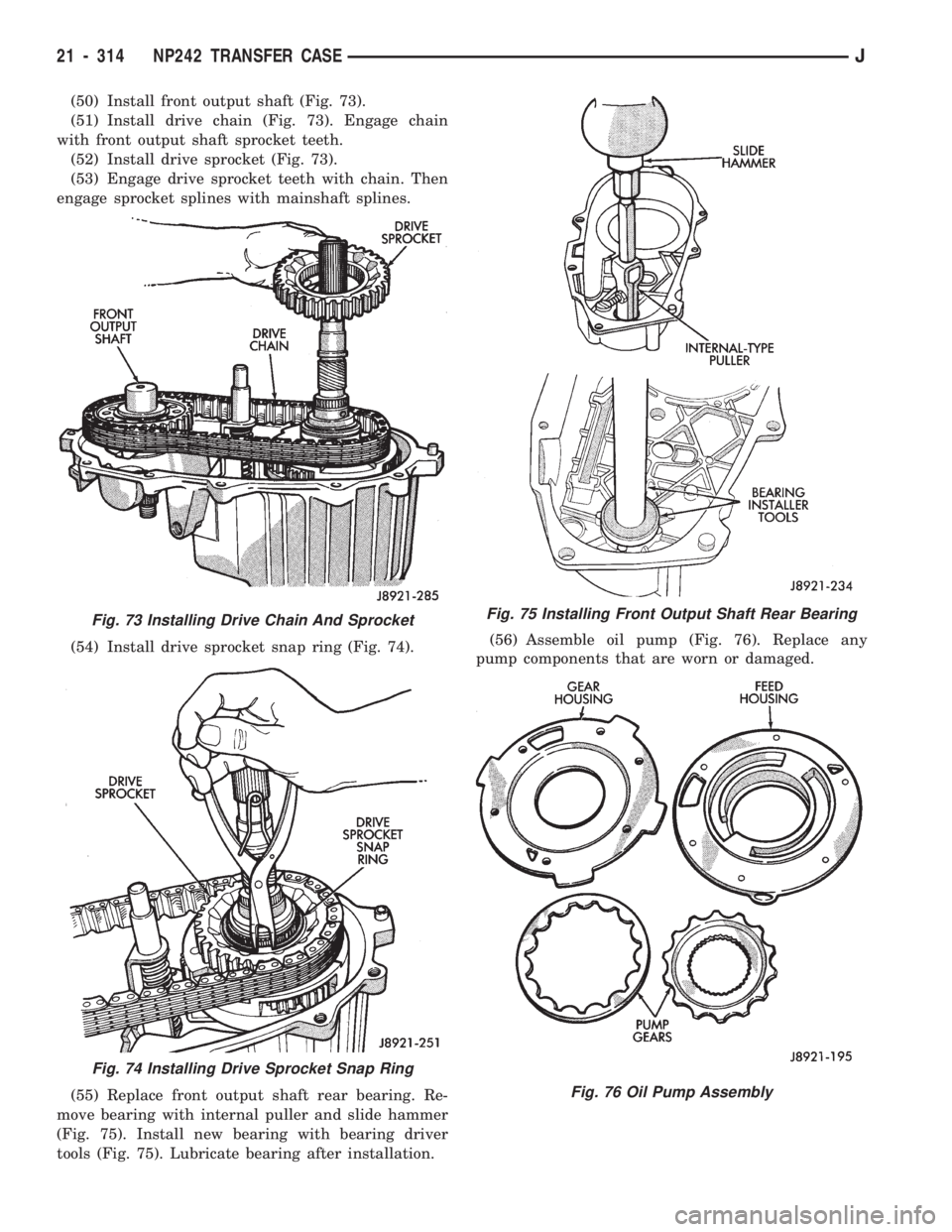
(50) Install front output shaft (Fig. 73).
(51) Install drive chain (Fig. 73). Engage chain
with front output shaft sprocket teeth.
(52) Install drive sprocket (Fig. 73).
(53) Engage drive sprocket teeth with chain. Then
engage sprocket splines with mainshaft splines.
(54) Install drive sprocket snap ring (Fig. 74).
(55) Replace front output shaft rear bearing. Re-
move bearing with internal puller and slide hammer
(Fig. 75). Install new bearing with bearing driver
tools (Fig. 75). Lubricate bearing after installation.(56) Assemble oil pump (Fig. 76). Replace any
pump components that are worn or damaged.
Fig. 73 Installing Drive Chain And Sprocket
Fig. 74 Installing Drive Sprocket Snap Ring
Fig. 75 Installing Front Output Shaft Rear Bearing
Fig. 76 Oil Pump Assembly
21 - 314 NP242 TRANSFER CASEJ
Page 1426 of 1784
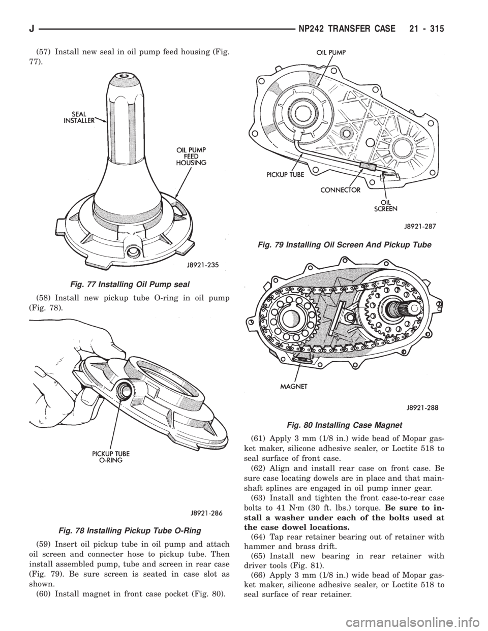
(57) Install new seal in oil pump feed housing (Fig.
77).
(58) Install new pickup tube O-ring in oil pump
(Fig. 78).
(59) Insert oil pickup tube in oil pump and attach
oil screen and connecter hose to pickup tube. Then
install assembled pump, tube and screen in rear case
(Fig. 79). Be sure screen is seated in case slot as
shown.
(60) Install magnet in front case pocket (Fig. 80).(61) Apply 3 mm (1/8 in.) wide bead of Mopar gas-
ket maker, silicone adhesive sealer, or Loctite 518 to
seal surface of front case.
(62) Align and install rear case on front case. Be
sure case locating dowels are in place and that main-
shaft splines are engaged in oil pump inner gear.
(63) Install and tighten the front case-to-rear case
bolts to 41 Nzm (30 ft. lbs.) torque.Be sure to in-
stall a washer under each of the bolts used at
the case dowel locations.
(64) Tap rear retainer bearing out of retainer with
hammer and brass drift.
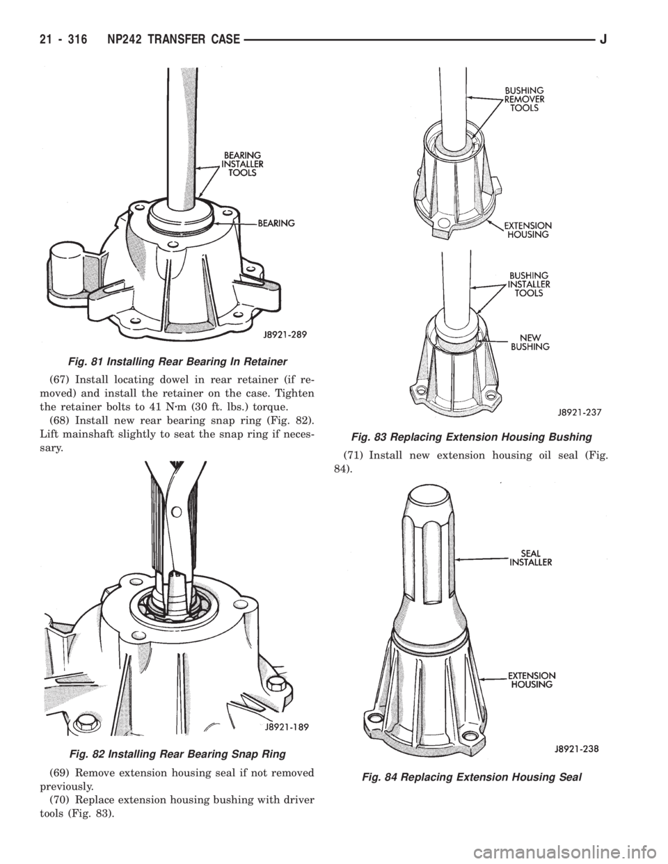
(65) Install new bearing in rear retainer with
driver tools (Fig. 81).
(66) Apply 3 mm (1/8 in.) wide bead of Mopar gas-
ket maker, silicone adhesive sealer, or Loctite 518 to
seal surface of rear retainer.
Fig. 77 Installing Oil Pump seal
Fig. 78 Installing Pickup Tube O-Ring
Fig. 79 Installing Oil Screen And Pickup Tube
Fig. 80 Installing Case Magnet
JNP242 TRANSFER CASE 21 - 315
Page 1427 of 1784
(67) Install locating dowel in rear retainer (if re-
moved) and install the retainer on the case. Tighten
the retainer bolts to 41 Nzm (30 ft. lbs.) torque.
(68) Install new rear bearing snap ring (Fig. 82).
Lift mainshaft slightly to seat the snap ring if neces-
sary.
(69) Remove extension housing seal if not removed
previously.
(70) Replace extension housing bushing with driver
tools (Fig. 83).(71) Install new extension housing oil seal (Fig.
84).
Fig. 83 Replacing Extension Housing Bushing
Fig. 84 Replacing Extension Housing Seal
Fig. 81 Installing Rear Bearing In Retainer
Fig. 82 Installing Rear Bearing Snap Ring
21 - 316 NP242 TRANSFER CASEJ
Page 1436 of 1784
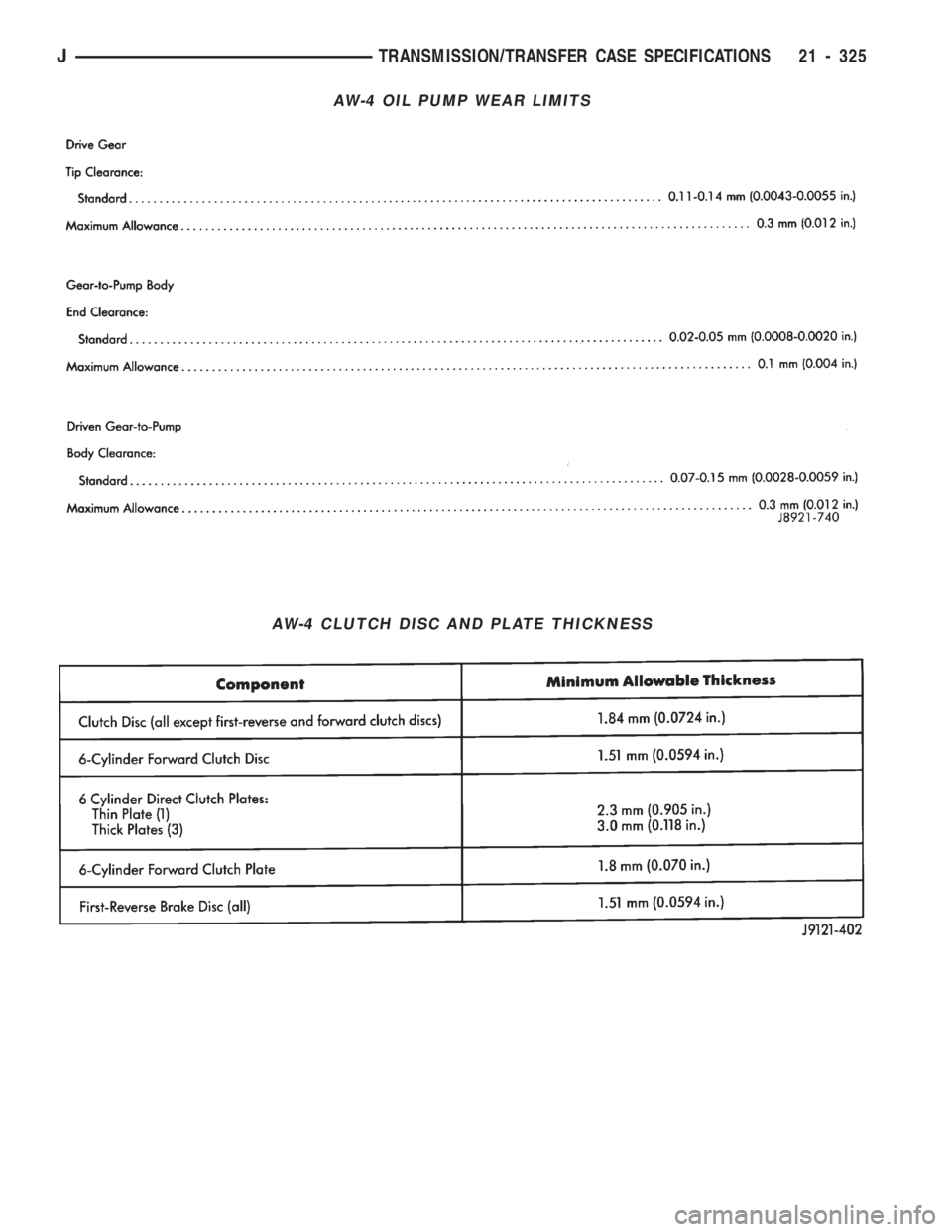
AW-4 OIL PUMP WEAR LIMITS
AW-4 CLUTCH DISC AND PLATE THICKNESS
JTRANSMISSION/TRANSFER CASE SPECIFICATIONS 21 - 325
Page 1445 of 1784
TIRE CHAINS
Tire snow chains may be used on certain models.
Refer to Owner's Manual for more information.
CLEANING OF TIRES
Steam cleaning may be used for cleaning.
DO NOT use gasoline or wire brush for cleaning.
DO NOT use mineral oil or an oil-based solvent.
PRESSURE GAUGES
High-quality, dial-type, air-pressure gauges are
recommended. After checking with the gauge, re-
place valve cap and finger tight.
TIRE INFLATION PRESSURES
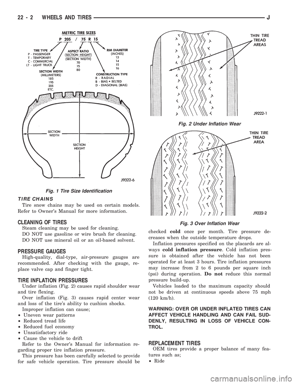
Under inflation (Fig. 2) causes rapid shoulder wear
and tire flexing.
Over inflation (Fig. 3) causes rapid center wear
and loss of the tire's ability to cushion shocks.
Improper inflation can cause;
²Uneven wear patterns
²Reduced tread life
²Reduced fuel economy
²Unsatisfactory ride
²Cause the vehicle to drift
Refer to the Owner's Manual for information re-
garding proper tire inflation pressure.
This pressure has been carefully selected to provide
for safe vehicle operation. Tire pressure should becheckedcoldonce per month. Tire pressure de-
creases when the outside temperature drops.
Inflation pressures specified on the placards are al-
wayscold inflation pressure. Cold inflation pres-
sure is obtained after the vehicle has not been
operated for at least 3 hours. Tire inflation pressures
may increase from 2 to 6 pounds per square inch
(psi) during operation.Do notreduce this normal
pressure build-up.
Vehicles loaded to the maximum capacity should
not be driven at continuous speeds above 75 mph
(120 km/h).
WARNING: OVER OR UNDER INFLATED TIRES CAN
AFFECT VEHICLE HANDLING AND CAN FAIL SUD-
DENLY, RESULTING IN LOSS OF VEHICLE CON-
TROL.
REPLACEMENT TIRES
OEM tires provide a proper balance of many fea-
tures such as;
²Ride
Fig. 1 Tire Size Identification
Fig. 2 Under Inflation Wear
Fig. 3 Over Inflation Wear
22 - 2 WHEELS AND TIRESJ
Page 1449 of 1784
WHEELS
GENERAL INFORMATION
Original equipment wheels are designed for the
specified Maximum Vehicle Capacity.
All models use steel or cast aluminum drop center
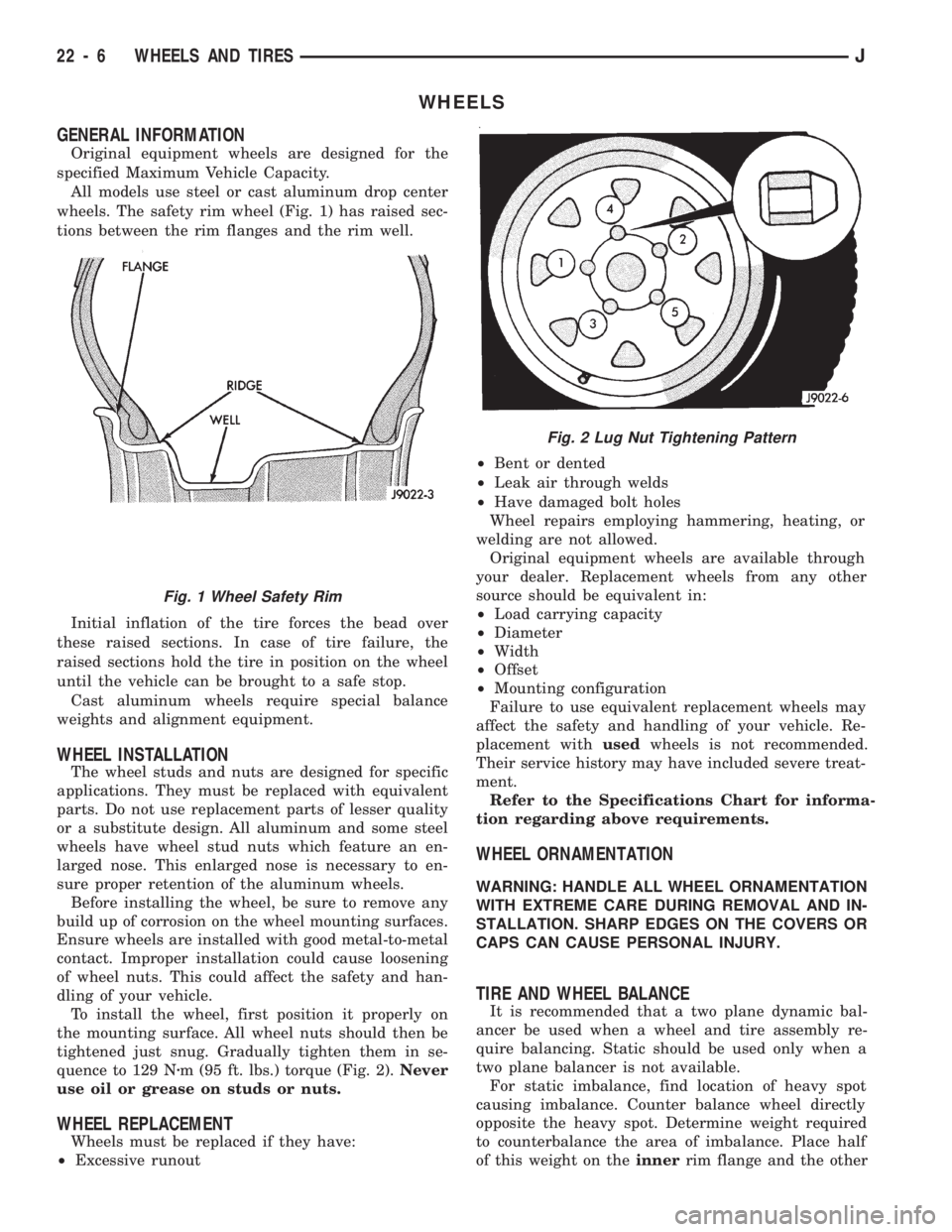
wheels. The safety rim wheel (Fig. 1) has raised sec-
tions between the rim flanges and the rim well.
Initial inflation of the tire forces the bead over
these raised sections. In case of tire failure, the
raised sections hold the tire in position on the wheel
until the vehicle can be brought to a safe stop.
Cast aluminum wheels require special balance
weights and alignment equipment.
WHEEL INSTALLATION
The wheel studs and nuts are designed for specific
applications. They must be replaced with equivalent
parts. Do not use replacement parts of lesser quality
or a substitute design. All aluminum and some steel
wheels have wheel stud nuts which feature an en-
larged nose. This enlarged nose is necessary to en-
sure proper retention of the aluminum wheels.
Before installing the wheel, be sure to remove any
build up of corrosion on the wheel mounting surfaces.
Ensure wheels are installed with good metal-to-metal
contact. Improper installation could cause loosening
of wheel nuts. This could affect the safety and han-
dling of your vehicle.
To install the wheel, first position it properly on
the mounting surface. All wheel nuts should then be
tightened just snug. Gradually tighten them in se-
quence to 129 Nzm (95 ft. lbs.) torque (Fig. 2).Never
use oil or grease on studs or nuts.
WHEEL REPLACEMENT
Wheels must be replaced if they have:
²Excessive runout²Bent or dented
²Leak air through welds
²Have damaged bolt holes
Wheel repairs employing hammering, heating, or
welding are not allowed.
Original equipment wheels are available through
your dealer. Replacement wheels from any other
source should be equivalent in:
²Load carrying capacity
²Diameter
²Width
²Offset
²Mounting configuration
Failure to use equivalent replacement wheels may
affect the safety and handling of your vehicle. Re-
placement withusedwheels is not recommended.
Their service history may have included severe treat-
ment.
Refer to the Specifications Chart for informa-
tion regarding above requirements.
WHEEL ORNAMENTATION
WARNING: HANDLE ALL WHEEL ORNAMENTATION
WITH EXTREME CARE DURING REMOVAL AND IN-
STALLATION. SHARP EDGES ON THE COVERS OR
CAPS CAN CAUSE PERSONAL INJURY.
TIRE AND WHEEL BALANCE
It is recommended that a two plane dynamic bal-
ancer be used when a wheel and tire assembly re-
quire balancing. Static should be used only when a
two plane balancer is not available.
For static imbalance, find location of heavy spot
causing imbalance. Counter balance wheel directly
opposite the heavy spot. Determine weight required
to counterbalance the area of imbalance. Place half
of this weight on theinnerrim flange and the other
Fig. 2 Lug Nut Tightening Pattern
Fig. 1 Wheel Safety Rim
22 - 6 WHEELS AND TIRESJ
Page 1525 of 1784
INSTALLATION
(1) Connect the replacement support rod and cylin-
der to the ball studs.
(2) Secure the support rod and cylinder to the ball
studs with the retainer clips.
(3) Remove the support from the liftgate and test
the operation of the support rod.
LIFTGATE SUPPORT ROD CYLINDER DISPOSAL
WARNING: SAFETY GOGGLES MUST BE WORN
DURING THE DISPOSAL PROCEDURE. THE HIGH
PRESSURE GAS CHARGE IN THE SUPPORT ROD
CYLINDERS WILL BE RELEASED DURING THE
PROCEDURE.
(1) Remove the support rod cylinder(s) from the
liftgate.
(2) Position the support rod cylinder horizontally
in a vise and clamp the cylinder securely.
(3) Wrap the cylinder with 4-5 layers of shop tow-
els.
(4) Measure 1 and 1/2 inches inward from the end
of the cylinder. Mark this location on the towels with
chalk. The cylinder will be punctured at this location
to release the gas charge.
(5) Use a punch and hammer to puncture cylinder.
Force the punch through towels and into the cylinder
with a hammer. Continue striking the punch until
the gas begins to escapebut do not remove the
punch.
(6) Hold the towels and punch in position until all
the gas has escaped. Complete de-pressurization will
require about 4 to 10 seconds. After all the gas has
escaped, slowly remove the punch.
(7) Hold a towel over the hole in cylinder and press
the support rod piston all the way into the cylinder
to purge remaining oil.
(8) Remove the support rod cylinder from the vise
and discard it.
(9) If both support rod cylinders are being re-
placed, repeat this procedure for the remaining cylin-
der.
LIFTGATE SUPPORT ROD BALL STUD
REPLACEMENT
REMOVAL
(1) Open the liftgate.
(2) Support the liftgate in the open position.
(3) Remove the retainer clip that attaches the sup-
port rod and cylinder to the ball stud.
(4) Disconnect the support rod from the ball stud.
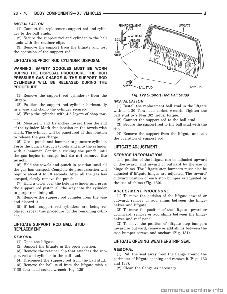
(5) Remove the ball stud from the liftgate with a
T-30 Torx-head socket wrench (Fig. 129).
INSTALLATION
(1) Install the replacement ball stud in the liftgate
with a T-30 Torx-head socket wrench. Tighten the
ball stud to 7 Nzm (62 in-lbs) torque.
(2) Connect the support rod to the ball stud.
(3) Secure the support rod to the ball stud with the
clip.
(4) Remove the support from the liftgate and test
the operation of support rod.
LIFTGATE ADJUSTMENT
SERVICE INFORMATION
The position of the liftgate can be adjusted upward
or downward, and inward or outward by the use of
hinge shims. The liftgate stop bumpers must also be
adjusted if liftgate hinges are adjusted. The inward/
outward position of each stop bumper is adjusted by
the use of shims (Fig. 130).
ADJUSTMENT PROCEDURE
(1) To move the position of the liftgate inward or
outward, remove or add shims between the hinge-
halves and liftgate.
(2) To move the position of the liftgate upward or
downward, remove or add shims between the hinge-
halves and roof panel.
(3) To move the position of liftgate stop bumpers
inward or outward, remove or add shims between the
stop bumper screws and anchors (Fig. 131).
LIFTGATE OPENING WEATHERSTRIP SEAL
REMOVAL
(1) Pull the seal away from the flange around the
perimeter of liftgate opening and remove it (Figs. 132
and 133).
(2) Clean the flange as necessary.
Fig. 129 Support Rod Ball Studs
23 - 70 BODY COMPONENTSÐXJ VEHICLESJ
Page 1620 of 1784
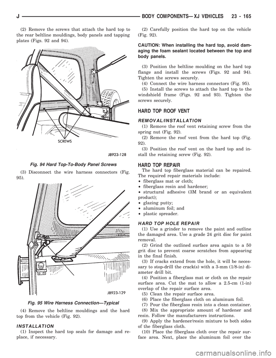
(2) Remove the screws that attach the hard top to
the rear beltline mouldings, body panels and tapping
plates (Figs. 92 and 94).
(3) Disconnect the wire harness connectors (Fig.
95).
(4) Remove the beltline mouldings and the hard
top from the vehicle (Fig. 92).
INSTALLATION
(1) Inspect the hard top seals for damage and re-
place, if necessary.(2) Carefully position the hard top on the vehicle
(Fig. 92).
CAUTION: When installing the hard top, avoid dam-
aging the foam sealant located between the top and
body panels.
(3) Position the beltline moulding on the hard top
flange and install the screws (Figs. 92 and 94).
Tighten the screws securely.
(4) Connect the wire harness connectors (Fig. 95).
(5) Install the screws to attach the hard top to the
windshield frame (Figs. 92 and 93). Tighten the
screws securely.
HARD TOP ROOF VENT
REMOVAL/INSTALLATION
(1) Remove the roof vent retaining screw from the
spring nut (Fig. 92).
(2) Remove the roof vent from the hard top (Fig.
92).
(3) Position the roof vent on the hard top and in-
stall the retaining screw (Fig. 92).
HARD TOP REPAIR
The hard top fiberglass material can be repaired.
The required repair materials include:
²fiberglass mat or cloth;
²fiberglass resin and hardener;
²structural adhesive (3M brand or an equivalent
product);
²glazing putty;
²aluminum foil; and
²plastic spreader.
HARD TOP HOLE REPAIR
(1) Use a grinder to remove the paint and outline
the damaged area. Use a grade 24 grit disc for paint
removal.
(2) Grind the outlined surface area again to a 50
grit disc to prevent coarse scratches from appearing
in the final finish.
(3) If cracks extend from the hole, it will be neces-
sary to stop-drill the crack(s) with a 3-mm (1/8-in) di-
ameter drill bit.
(4) Position a fiberglass mat or cloth on the repair
surface area. Cut the mat to allow a 2.5-cm (1-in)
overlap of the repair surface area.
(5) Clean the repair surface area.
(6) Place the fiberglass cloth on aluminum foil.
(7) Pour the fiberglass resin into a clean container.
(8) Mix the appropriate amount of hardener and
resin. Follow the manufacturers instructions.
(9) Apply the hardener/resin mixture to both sides
of the fiberglass cloth.
(10) Place the fiberglass cloth over the repair sur-
face area. Next, place the aluminum foil over the
Fig. 94 Hard Top-To-Body Panel Screws
Fig. 95 Wire Harness ConnectionÐTypical
JBODY COMPONENTSÐXJ VEHICLES 23 - 165