1994 JEEP CHEROKEE lock
[x] Cancel search: lockPage 923 of 1784
DO NOT rotate the crankshaft. This will cause
the Plastigage to shift, resulting in an inaccurate
reading. Plastigage must not be permitted to
crumble. If brittle, obtain fresh stock.
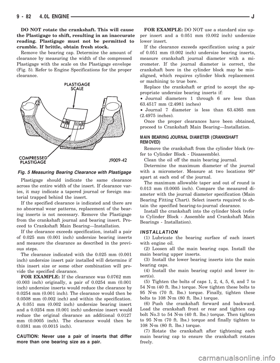
Remove the bearing cap. Determine the amount of
clearance by measuring the width of the compressed
Plastigage with the scale on the Plastigage envelope
(Fig. 5). Refer to Engine Specifications for the proper
clearance.
Plastigage should indicate the same clearance
across the entire width of the insert. If clearance var-
ies, it may indicate a tapered journal or foreign ma-
terial trapped behind the insert.
If the specified clearance is indicated and there are
no abnormal wear patterns, replacement of the bear-
ing inserts is not necessary. Remove the Plastigage
from the crankshaft journal and bearing insert. Pro-
ceed to Crankshaft Main BearingÐInstallation.
If the clearance exceeds specification, install a pair
of 0.025 mm (0.001 inch) undersize bearing inserts
and measure the clearance as described in the previ-
ous steps.
The clearance indicated with the 0.025 mm (0.001
inch) undersize insert pair installed will determine if
this insert size or some other combination will pro-
vide the specified clearance.
FOR EXAMPLE:If the clearance was 0.0762 mm
(0.003 inch) originally, a pair of 0.0254 mm (0.001
inch) undersize inserts would reduce the clearance by
0.0254 mm (0.001 inch). The clearance would then be
0.0508 mm (0.002 inch) and within the specification.
A 0.051 mm (0.002 inch) undersize bearing insert
and a 0.0254 mm (0.001 inch) undersize insert would
reduce the original clearance an additional 0.0127
mm (0.0005 inch). The clearance would then be
0.0381 mm (0.0015 inch).
CAUTION: Never use a pair of inserts that differ
more than one bearing size as a pair.FOR EXAMPLE:DO NOT use a standard size up-
per insert and a 0.051 mm (0.002 inch) undersize
lower insert.
If the clearance exceeds specification using a pair
of 0.051 mm (0.002 inch) undersize bearing inserts,
measure crankshaft journal diameter with a mi-
crometer. If the journal diameter is correct, the
crankshaft bore in the cylinder block may be mis-
aligned, which requires cylinder block replacement
or machining to true bore.
Replace the crankshaft or grind to accept the ap-
propriate undersize bearing inserts if:
²Journal diameters 1 through 6 are less than
63.4517 mm (2.4981 inches)
²Journal 7 diameter is less than 63.4365 mm
(2.4975 inches).
Once the proper clearances have been obtained,
proceed to Crankshaft Main BearingÐInstallation.
MAIN BEARING JOURNAL DIAMETER (CRANKSHAFT
REMOVED)
Remove the crankshaft from the cylinder block (re-
fer to Cylinder Block - Disassemble).
Clean the oil off the main bearing journal.
Determine the maximum diameter of the journal
with a micrometer. Measure at two locations 90É
apart at each end of the journal.
The maximum allowable taper and out of round is
0.013 mm (0.0005 inch). Compare the measured di-
ameter with the journal diameter specification (Main
Bearing Fitting Chart). Select inserts required to ob-
tain the specified bearing-to-journal clearance.
Install the crankshaft into the cylinder block (refer
to Cylinder Block - Assemble and Crankshaft Main
Bearings - Installation).
INSTALLATION
(1) Lubricate the bearing surface of each insert
with engine oil.
(2) Loosen all the main bearing caps. Install the
main bearing upper inserts.
(3) Install the lower bearing inserts into the main
bearing caps.
(4) Install the main bearing cap(s) and lower in-
sert(s).
(5) Tighten the bolts of caps 1, 2, 4, 5, 6, and 7 to
54 Nzm (40 ft. lbs.) torque. Now tighten these bolts to
95 Nzm (70 ft. lbs.) torque. Finally, tighten these
bolts to 108 Nzm (80 ft. lbs.) torque.
(6) Push the crankshaft forward and backward.
Load the crankshaft front or rear and tighten cap
bolt No.3 to 54 Nzm (40 ft. lbs.) torque. Then tighten
to 95 Nzm (70 ft. lbs.) torque and finally tighten to
108 Nzm (80 ft. lbs.) torque.
(7) Rotate the crankshaft after tightening each
main bearing cap to ensure the crankshaft rotates
freely.
Fig. 5 Measuring Bearing Clearance with Plastigage
9 - 82 4.0L ENGINEJ
Page 925 of 1784

(8) Check crankshaft end play. Crankshaft end
play is controlled by the thrust bearing which is
flange and installed at the No.2 main bearing posi-
tion.
(a) Attach a magnetic base dial indicator to the
cylinder block at either the front or rear of the en-
gine.
(b) Position the dial indicator rod so that it is
parallel to the center line of the crankshaft.
(c) Pry the crankshaft forward, position the dial
indicator to zero.
(d) Pry the crankshaft forward and backward.
Note the dial indicator readings. End play is the
difference between the high and low measurements
(Fig. 6). Correct end play is 0.038-0.165 mm
(0.0015-0.0065 inch). The desired specifications are
0.051-0.064 mm (0.002-0.0025 inch).
(e) If end play is not within specification, inspect
crankshaft thrust faces for wear. If no wear is ap-
parent, replace the thrust bearing and measure end
play. If end play is still not within specification, re-
place the crankshaft.
If the crankshaft was removed, install the crank-
shaft into the cylinder block (refer to Cylinder Block -
Assemble).
(9) Install the oil pan.
(10) Install the drain plug. Tighten the plug to 34
Nzm (25 ft. lbs.) torque.
(11) Lower the vehicle.
(12) Install the spark plugs. Tighten the plugs to
37 Nzm (27 ft. lbs.) torque.
(13) Fill the oil pan with engine oil to the full
mark on the dipstick level.
(14) Connect negative cable to battery.
REAR MAIN OIL SEALS
The crankshaft rear main bearing oil seal consists
of two half pieces of viton with a single lip that ef-fectively seals the rear of the crankshaft. Replace the
upper and lower seal halves as a unit to ensure leak-
free operation.
REMOVAL
(1) Remove the engine flywheel or converter drive
plate.
(2) Remove the oil pan.
(3) Remove the rear main bearing cap (No.7).
(4) Push the upper seal out of the groove. Ensure
that the crankshaft and seal groove are not damaged.
(5) Remove the lower half of the seal from the
bearing cap.
INSTALLATION
(1) Wipe the seal surface area of the crankshaft
until it is clean.
(2) Apply a thin coat of engine oil.
(3) Coat the lip of the seal with engine oil.
(4) Carefully position the upper seal into the
groove in the cylinder block. The lip of the seal faces
toward the front of the engine.
(5) Place the lower half of the seal into bearing cap
No.7 (Fig. 7).
(6) Coat the outer curved surface of the lower seal
with soap and the lip of the seal with engine oil (Fig.
7).
(7) Position the lower seal into the bearing cap re-
cess and seat it firmly. Be sure the seal is flush with
the cylinder block pan rail.
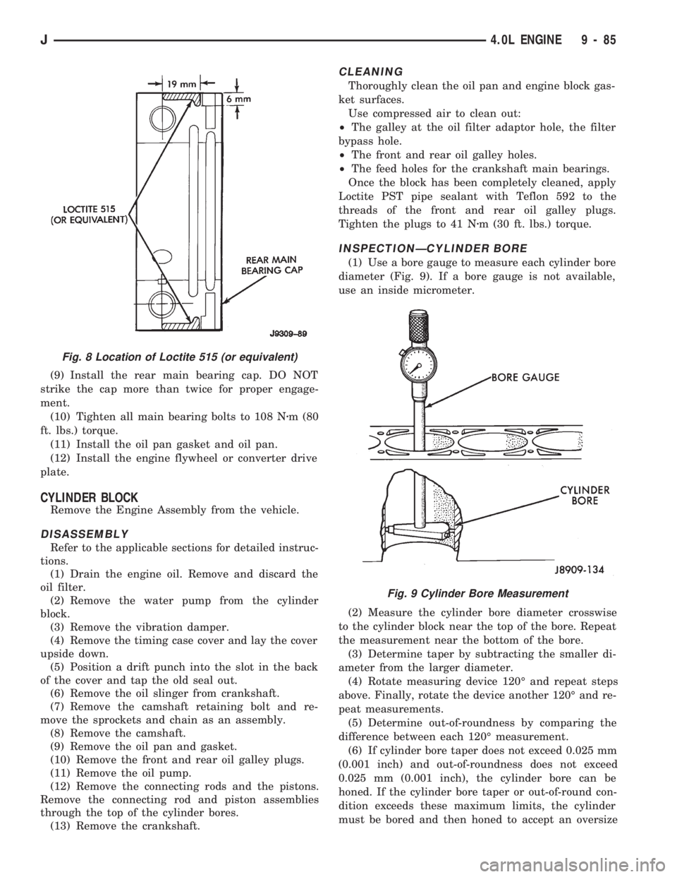
(8) Apply Loctite 515, or equivalent on the rear
bearing cap (Fig. 8). The bead should be 3 mm (0.125
in) thick. DO NOT apply Loctite 515, or equivalent
to the lip of the seal.
Fig. 7 Rear Main Bearing Oil Seal
Fig. 6 Crankshaft End Play Measurement
9 - 84 4.0L ENGINEJ
Page 926 of 1784
(9) Install the rear main bearing cap. DO NOT
strike the cap more than twice for proper engage-
ment.
(10) Tighten all main bearing bolts to 108 Nzm (80
ft. lbs.) torque.
(11) Install the oil pan gasket and oil pan.
(12) Install the engine flywheel or converter drive
plate.
CYLINDER BLOCK
Remove the Engine Assembly from the vehicle.
DISASSEMBLY
Refer to the applicable sections for detailed instruc-
tions.
(1) Drain the engine oil. Remove and discard the
oil filter.
(2) Remove the water pump from the cylinder
block.
(3) Remove the vibration damper.
(4) Remove the timing case cover and lay the cover
upside down.
(5) Position a drift punch into the slot in the back
of the cover and tap the old seal out.
(6) Remove the oil slinger from crankshaft.
(7) Remove the camshaft retaining bolt and re-
move the sprockets and chain as an assembly.
(8) Remove the camshaft.
(9) Remove the oil pan and gasket.
(10) Remove the front and rear oil galley plugs.
(11) Remove the oil pump.
(12) Remove the connecting rods and the pistons.
Remove the connecting rod and piston assemblies
through the top of the cylinder bores.
(13) Remove the crankshaft.
CLEANING
Thoroughly clean the oil pan and engine block gas-
ket surfaces.
Use compressed air to clean out:
²The galley at the oil filter adaptor hole, the filter
bypass hole.
²The front and rear oil galley holes.
²The feed holes for the crankshaft main bearings.
Once the block has been completely cleaned, apply
Loctite PST pipe sealant with Teflon 592 to the
threads of the front and rear oil galley plugs.
Tighten the plugs to 41 Nzm (30 ft. lbs.) torque.
INSPECTIONÐCYLINDER BORE
(1) Use a bore gauge to measure each cylinder bore
diameter (Fig. 9). If a bore gauge is not available,
use an inside micrometer.
(2) Measure the cylinder bore diameter crosswise
to the cylinder block near the top of the bore. Repeat
the measurement near the bottom of the bore.
(3) Determine taper by subtracting the smaller di-
ameter from the larger diameter.
(4) Rotate measuring device 120É and repeat steps
above. Finally, rotate the device another 120É and re-
peat measurements.
(5) Determine out-of-roundness by comparing the
difference between each 120É measurement.
(6) If cylinder bore taper does not exceed 0.025 mm
(0.001 inch) and out-of-roundness does not exceed
0.025 mm (0.001 inch), the cylinder bore can be
honed. If the cylinder bore taper or out-of-round con-
dition exceeds these maximum limits, the cylinder
must be bored and then honed to accept an oversize
Fig. 8 Location of Loctite 515 (or equivalent)
Fig. 9 Cylinder Bore Measurement
J4.0L ENGINE 9 - 85
Page 937 of 1784
red. Remove the exhaust tailpipe/muffler clamp and
twist the exhaust tailpipe out of the muffler.
INSTALLATION
(1) Install the muffler onto the catalytic converter.
Install the clamp and tighten the nuts finger tight.
(2) Install the exhaust tailpipe into the rear of the
muffler.
(3) Install the exhaust tailpipe/muffler assembly
on the rear exhaust tailpipe hanger. Make sure that
the exhaust tailpipe has sufficient clearance from the
floor pan.
(4) Install the remaining clamps and the front ex-
haust tailpipe hanger.
(5) Tighten the nuts on the muffler-to-catalytic
converter clamp to 61 Nzm (45 ft. lbs.) torque (Fig.
6). Tighten the nuts on the rear exhaust tailpipe
clamp to 14 Nzm (10 ft. lbs.) torque (Fig. 7).
(6) Lower the vehicle.
(7) Start the engine and inspect for exhaust leaks
and exhaust system contact with the body panels.
Adjust the alignment, if needed.
MUFFLER AND EXHAUST TAILPIPEÐYJ VEHICLES
All original equipment exhaust systems are manu-
factured with the exhaust tailpipe welded to the muf-
fler. Service replacement mufflers and exhaust
tailpipes are clamped together.
WARNING: IF TORCHES ARE USED WHEN WORK-
ING ON THE EXHAUST SYSTEM, DO NOT ALLOW
THE FLAME NEAR THE FUEL LINES.
REMOVAL
(1) Raise the vehicle and support the rear of the
vehicle by the side rails and allow the axle to hang
free.
(2) Remove the front muffler clamp from the cata-
lytic converter and muffler connection (Fig. 6).
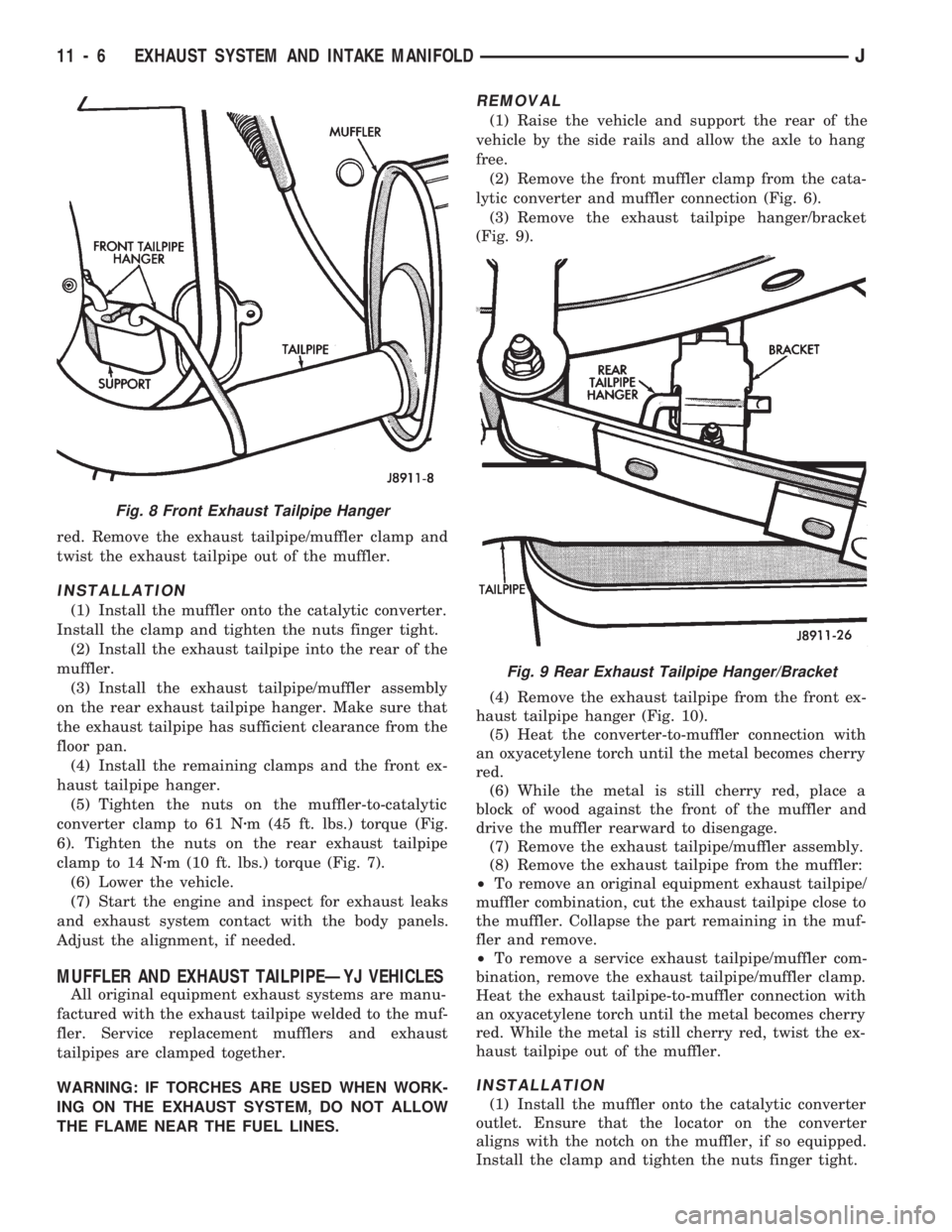
(3) Remove the exhaust tailpipe hanger/bracket
(Fig. 9).
(4) Remove the exhaust tailpipe from the front ex-
haust tailpipe hanger (Fig. 10).
(5) Heat the converter-to-muffler connection with
an oxyacetylene torch until the metal becomes cherry
red.
(6) While the metal is still cherry red, place a
block of wood against the front of the muffler and
drive the muffler rearward to disengage.
(7) Remove the exhaust tailpipe/muffler assembly.
(8) Remove the exhaust tailpipe from the muffler:
²To remove an original equipment exhaust tailpipe/
muffler combination, cut the exhaust tailpipe close to
the muffler. Collapse the part remaining in the muf-
fler and remove.
²To remove a service exhaust tailpipe/muffler com-
bination, remove the exhaust tailpipe/muffler clamp.
Heat the exhaust tailpipe-to-muffler connection with
an oxyacetylene torch until the metal becomes cherry
red. While the metal is still cherry red, twist the ex-
haust tailpipe out of the muffler.
INSTALLATION
(1) Install the muffler onto the catalytic converter
outlet. Ensure that the locator on the converter
aligns with the notch on the muffler, if so equipped.
Install the clamp and tighten the nuts finger tight.
Fig. 8 Front Exhaust Tailpipe Hanger
Fig. 9 Rear Exhaust Tailpipe Hanger/Bracket
11 - 6 EXHAUST SYSTEM AND INTAKE MANIFOLDJ
Page 939 of 1784
INTAKE MANIFOLDÐ2.5L ENGINE
REMOVAL
(1) Disconnect the battery negative cable.
(2) Remove the air inlet hose from the throttle
body and air cleaner.
(3) Loosen the accessory drive belt tension and re-
move the belt from the power steering pump.
(4) Remove the power steering pump and brackets
from the water pump and intake manifold. Support
power steering pump and bracket with mechanics
wire attached to the radiator upper crossmember.
(5) Remove the fuel tank filler cap to relieve the
fuel tank pressure.
(6) Install the fuel tank filler cap.
(7) Disconnect fuel supply and return tube from
the fuel rail (refer to Group 14, Fuel System - Quick
Connect Fittings).
(8) Disconnect the accelerator cable from the throt-
tle body and the holddown bracket.
CAUTION: When disconnecting the cruise control
connector at the throttle body, DO NOT pry the con-
nector off with pliers or screwdriver. Use finger
pressure only. Prying the connector off could break
it.
(9) Disconnect the electrical connectors. Pull the
harnesses away from the manifold.
²The throttle position sensor.
²The idle speed control motor.
²The coolant temperature sensor at the thermostat.
²The manifold air temperature sensor at the intake
manifold.
²The fuel injectors.
²The oxygen sensor.
(10) Disconnect the crankcase ventilation (CCV)
vacuum hose and manifold absolute pressure (MAP)
sensor vacuum hose connector at the intake mani-
fold.
(11) Disconnect vacuum hose from vacuum port on
the intake manifold.
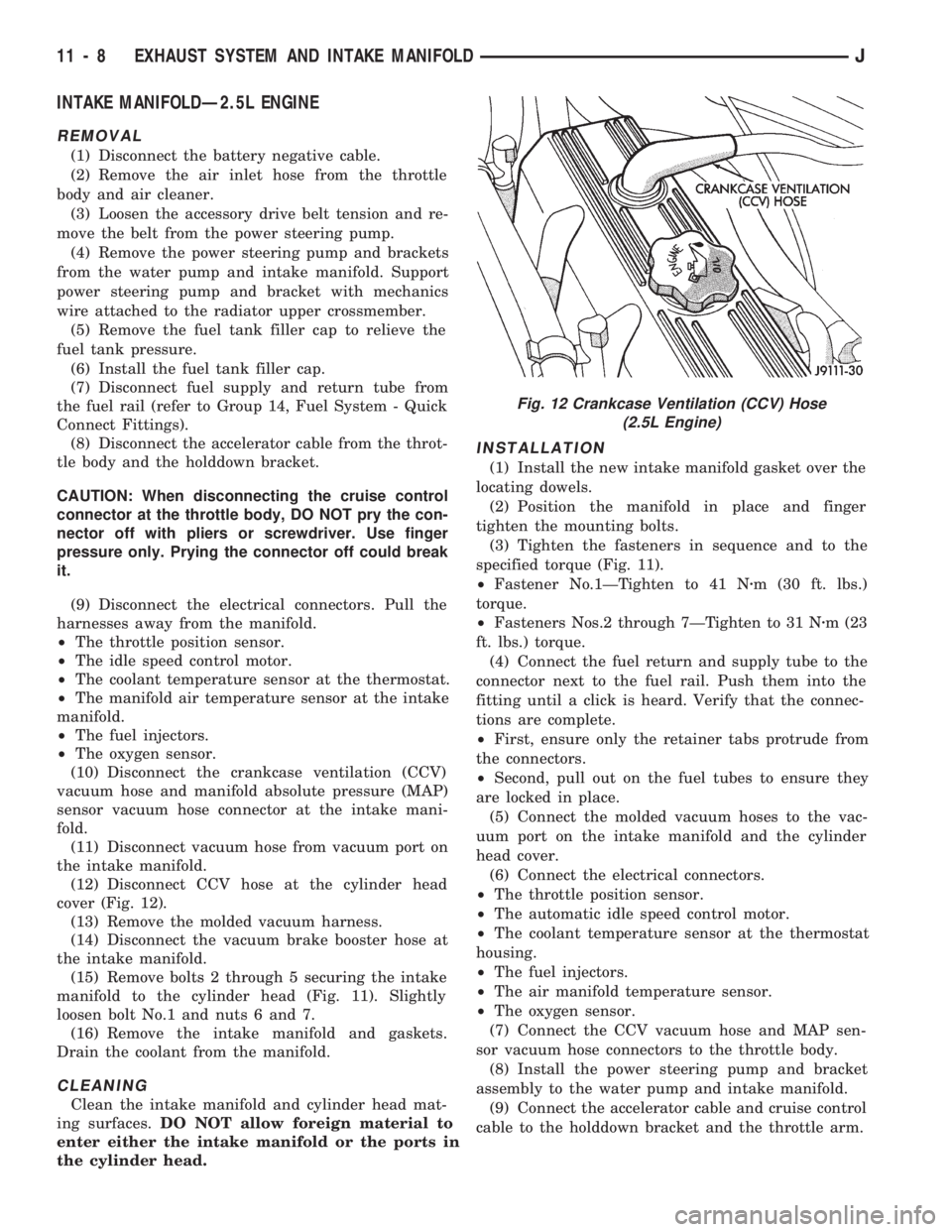
(12) Disconnect CCV hose at the cylinder head
cover (Fig. 12).
(13) Remove the molded vacuum harness.
(14) Disconnect the vacuum brake booster hose at
the intake manifold.
(15) Remove bolts 2 through 5 securing the intake
manifold to the cylinder head (Fig. 11). Slightly
loosen bolt No.1 and nuts 6 and 7.
(16) Remove the intake manifold and gaskets.
Drain the coolant from the manifold.
CLEANING
Clean the intake manifold and cylinder head mat-
ing surfaces.DO NOT allow foreign material to
enter either the intake manifold or the ports in
the cylinder head.
INSTALLATION
(1) Install the new intake manifold gasket over the
locating dowels.
(2) Position the manifold in place and finger
tighten the mounting bolts.
(3) Tighten the fasteners in sequence and to the
specified torque (Fig. 11).
²Fastener No.1ÐTighten to 41 Nzm (30 ft. lbs.)
torque.
²Fasteners Nos.2 through 7ÐTighten to 31 Nzm (23
ft. lbs.) torque.
(4) Connect the fuel return and supply tube to the
connector next to the fuel rail. Push them into the
fitting until a click is heard. Verify that the connec-
tions are complete.
²First, ensure only the retainer tabs protrude from
the connectors.
²Second, pull out on the fuel tubes to ensure they
are locked in place.
(5) Connect the molded vacuum hoses to the vac-
uum port on the intake manifold and the cylinder
head cover.
(6) Connect the electrical connectors.
²The throttle position sensor.
²The automatic idle speed control motor.
²The coolant temperature sensor at the thermostat
housing.
²The fuel injectors.
²The air manifold temperature sensor.
²The oxygen sensor.
(7) Connect the CCV vacuum hose and MAP sen-
sor vacuum hose connectors to the throttle body.
(8) Install the power steering pump and bracket
assembly to the water pump and intake manifold.
(9) Connect the accelerator cable and cruise control
cable to the holddown bracket and the throttle arm.
Fig. 12 Crankcase Ventilation (CCV) Hose
(2.5L Engine)
11 - 8 EXHAUST SYSTEM AND INTAKE MANIFOLDJ
Page 944 of 1784
XJ BUMPERS
INDEX
page page
Front Bumper............................ 3
Front Tow Hooks......................... 5Rear Bumper............................ 6
FRONT BUMPER
REMOVAL/DISASSEMBLY
(1) The bumper guards, end caps and tow hooks
can be removed from XJ front bumpers with the
bumper attached to the vehicle. Do not remove the
bumper from the vehicle if only these components re-
quire service.
If equipped with a brush guard, refer to the
Brush Guard Removal within Group 23ÐBody
Components.
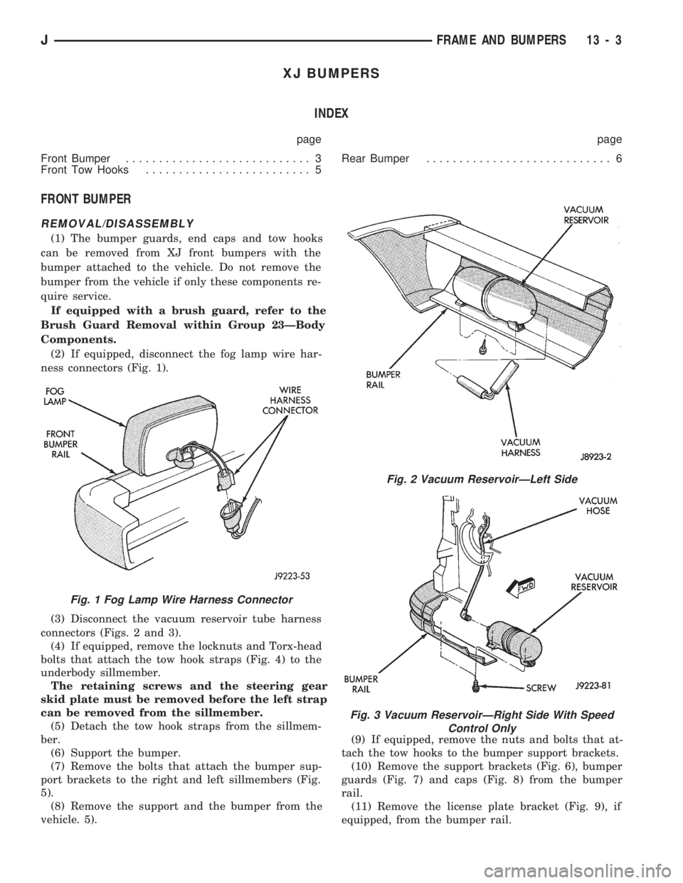
(2) If equipped, disconnect the fog lamp wire har-
ness connectors (Fig. 1).
(3) Disconnect the vacuum reservoir tube harness
connectors (Figs. 2 and 3).
(4) If equipped, remove the locknuts and Torx-head
bolts that attach the tow hook straps (Fig. 4) to the
underbody sillmember.
The retaining screws and the steering gear
skid plate must be removed before the left strap
can be removed from the sillmember.
(5) Detach the tow hook straps from the sillmem-
ber.
(6) Support the bumper.
(7) Remove the bolts that attach the bumper sup-
port brackets to the right and left sillmembers (Fig.
5).
(8) Remove the support and the bumper from the
vehicle. 5).(9) If equipped, remove the nuts and bolts that at-
tach the tow hooks to the bumper support brackets.
(10) Remove the support brackets (Fig. 6), bumper
guards (Fig. 7) and caps (Fig. 8) from the bumper
rail.
(11) Remove the license plate bracket (Fig. 9), if
equipped, from the bumper rail.
Fig. 1 Fog Lamp Wire Harness Connector
Fig. 2 Vacuum ReservoirÐLeft Side
Fig. 3 Vacuum ReservoirÐRight Side With Speed
Control Only
JFRAME AND BUMPERS 13 - 3
Page 946 of 1784
ets and bumper guards on the bumper rail. Tighten
hardware in the sequence indicated in Figure 7.
Tighten the locknuts with 20 Nzm (15 ft-lbs) torque.
Tighten bolts to 56 Nzm (41 ft-lbs) torque.(3) If not equipped with bumper guards, install the
bumper support brackets on the bumper rail. Tighten
bolts to 56 Nzm (41 ft-lbs) torque.
(4) If equipped with tow hooks, install the bolts
and nuts that attach them to the bumper support
brackets. Tighten nuts with 100 Nzm (74 ft-lbs)
torque.
(5) Install the bumper end caps on the bumper rail
(Fig. 8). Tighten nuts with 8 Nzm (72 in-lbs) torque.
(6) Install the license plate bracket on the bumper
rail. Tighten the nuts securely.
(7) If equipped, install the fog lamps on the
bumper rail. Tighten the nuts securely.
(8) If removed, install the vacuum reservoir(s) on
the bumper rail. Tighten the retaining screws and
bolts to 8 Nzm (72 in-lbs) torque.
(9) Position and support the bumper at the front of
the vehicle.
(10) Attach the bumper support brackets to the
right and left sillmembers and reinforcement brack-
ets. Tighten screws and bolts to 56 Nzm (41 ft-lbs)
torque.
(11) If equipped, install the Torx-head bolts and
locknuts that attach the tow hook straps to the un-
derbody sillmember. Tighten locknuts with 30 Nzm
(22 ft-lbs) torque.
Install the steering gear skid plate and screws
after the left tow hook strap has been installed.
(12) If equipped, connect the fog lamp wire harness
connectors.
(13) Connect the vacuum reservoir tube harness
connectors.
(14) Remove the bumper support.
FRONT TOW HOOKS
If a tow hook must be replaced or removed only for
service access, remove the nuts and bolts that attach
it to the bumper support bracket. When installing a
tow hook, tighten nuts with 100 Nzm (74 ft-lbs)
torque.
If a tow hook/bumper support bracket must be re-
placed, refer to the following removal and installa-
tion procedures.
REMOVAL
If equipped with a brush guard, refer to the
Brush Guard Removal within Group 23ÐBody
Components.
(1) If equipped, disconnect the fog lamp wire har-
ness connectors.
(2) Disconnect the vacuum reservoir tube harness
connectors.
(3) Support the bumper.
(4) Remove the bolts that attach the bumper sup-
port brackets to the right and left sillmembers.
(5) Remove the locknuts and Torx-head bolts that
attach the tow hook straps to the underbody sillmem-
ber.
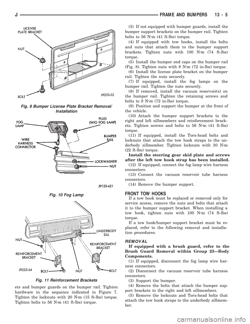
Fig. 9 Bumper License Plate Bracket Removal/
Installation
Fig. 10 Fog Lamp
Fig. 11 Reinforcement Brackets
JFRAME AND BUMPERS 13 - 5
Page 947 of 1784
The retaining screws and the steering gear
skid plate must be removed before the left strap
can be removed from the sillmember.
(6) Detach the tow hook straps from the sillmem-
ber.
(7) Remove the support and the bumper from the
vehicle.
(8) Remove the nuts and bolts that attach the tow
hooks to the bumper support brackets.
(9) Remove the tow hook from the bumper support
bracket (Fig. 4).
(10) Remove the support bracket from the bumper
rail.
INSTALLATION
(1) If equipped, install the bumper guard and
bumper support bracket on the bumper rail. Tighten
the retaining hardware in the sequence indicated in
Figure 7. Tighten locknuts to 20 Nzm (15 ft-lbs)
torque. Tighten bolts to 56 Nzm (41 ft-lbs) torque.
(2) If not equipped with bumper guards, install the
bumper support bracket on the bumper rail. Tighten
bolts to 56 Nzm (41 ft-lbs) torque.
(3) Position the tow hook at the support bracket.
Install the bolts and nuts that attach tow hook to the
bumper support bracket. (Fig. 4). Tighten nuts to 100
Nzm (74 ft-lbs) torque.
(4) Position and support the bumper at the front of
the vehicle.
(5) Attach the bumper support brackets to the
right and left sillmembers and reinforcement brack-
ets. Tighten screws and bolts to 56 Nzm (41 ft-lbs)
torque.
(6) If equipped, install the Torx-head bolts and
locknuts that attach the tow hook straps to the un-
derbody sillmember. Tighten locknuts to 30 Nzm (22
ft-lbs) torque.
Install the steering gear skid plate and screws
after the left tow hook strap has been installed.
(7) If equipped, connect the fog lamp wire harness
connectors. Connect the vacuum reservoir tube har-
ness connectors.
(8) Remove the bumper support.
REAR BUMPER
REMOVAL
(1) For vehicles equipped with a trailer hitch, re-
move the hitch before removing the bumper. If nec-
essary, refer to the removal procedure within Group
23ÐBody Components.
(2) Raise and support the rear of the vehicle.
(3) Support the bumper.
(4) Remove the bolts that attach the bumper sup-
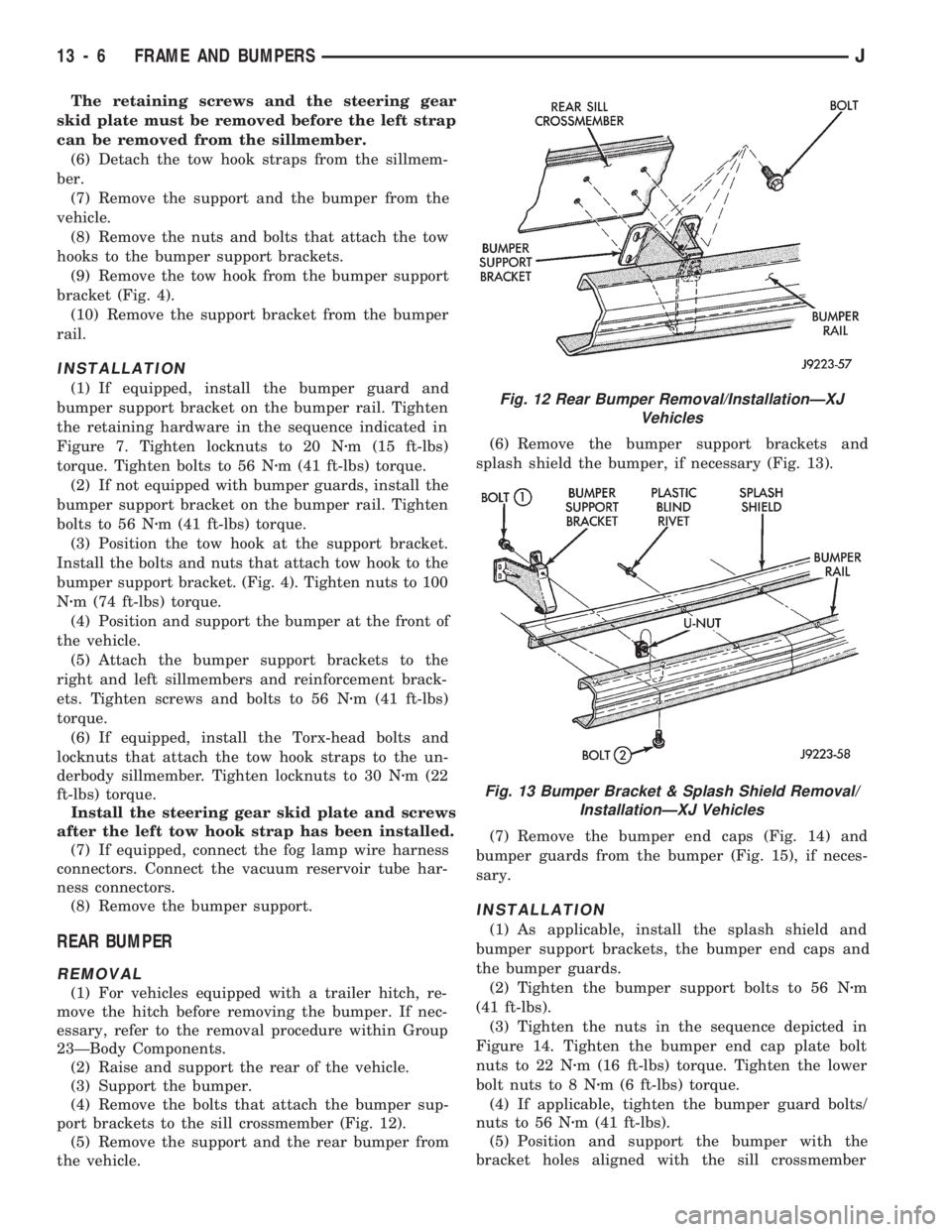
port brackets to the sill crossmember (Fig. 12).
(5) Remove the support and the rear bumper from
the vehicle.(6) Remove the bumper support brackets and
splash shield the bumper, if necessary (Fig. 13).
(7) Remove the bumper end caps (Fig. 14) and
bumper guards from the bumper (Fig. 15), if neces-
sary.
INSTALLATION
(1) As applicable, install the splash shield and
bumper support brackets, the bumper end caps and
the bumper guards.
(2) Tighten the bumper support bolts to 56 Nzm
(41 ft-lbs).
(3) Tighten the nuts in the sequence depicted in
Figure 14. Tighten the bumper end cap plate bolt
nuts to 22 Nzm (16 ft-lbs) torque. Tighten the lower
bolt nuts to 8 Nzm (6 ft-lbs) torque.
(4) If applicable, tighten the bumper guard bolts/
nuts to 56 Nzm (41 ft-lbs).
(5) Position and support the bumper with the
bracket holes aligned with the sill crossmember
Fig. 12 Rear Bumper Removal/InstallationÐXJ
Vehicles
Fig. 13 Bumper Bracket & Splash Shield Removal/
InstallationÐXJ Vehicles
13 - 6 FRAME AND BUMPERSJ