1994 JEEP CHEROKEE lock
[x] Cancel search: lockPage 994 of 1784
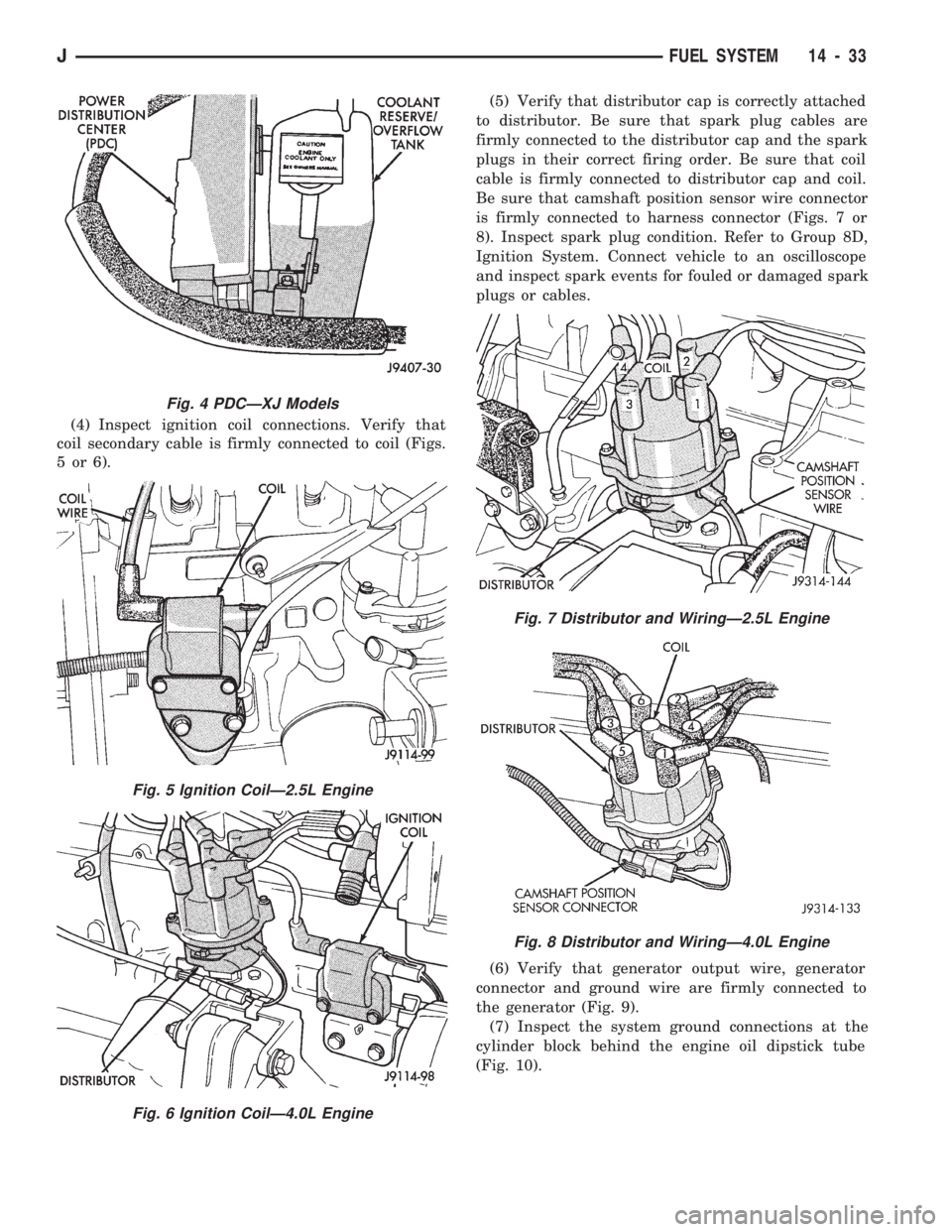
(4) Inspect ignition coil connections. Verify that
coil secondary cable is firmly connected to coil (Figs.
5or6).(5) Verify that distributor cap is correctly attached
to distributor. Be sure that spark plug cables are
firmly connected to the distributor cap and the spark
plugs in their correct firing order. Be sure that coil
cable is firmly connected to distributor cap and coil.
Be sure that camshaft position sensor wire connector
is firmly connected to harness connector (Figs. 7 or
8). Inspect spark plug condition. Refer to Group 8D,
Ignition System. Connect vehicle to an oscilloscope
and inspect spark events for fouled or damaged spark
plugs or cables.
(6) Verify that generator output wire, generator
connector and ground wire are firmly connected to
the generator (Fig. 9).
(7) Inspect the system ground connections at the
cylinder block behind the engine oil dipstick tube
(Fig. 10).
Fig. 4 PDCÐXJ Models
Fig. 5 Ignition CoilÐ2.5L Engine
Fig. 6 Ignition CoilÐ4.0L Engine
Fig. 7 Distributor and WiringÐ2.5L Engine
Fig. 8 Distributor and WiringÐ4.0L Engine
JFUEL SYSTEM 14 - 33
Page 1007 of 1784
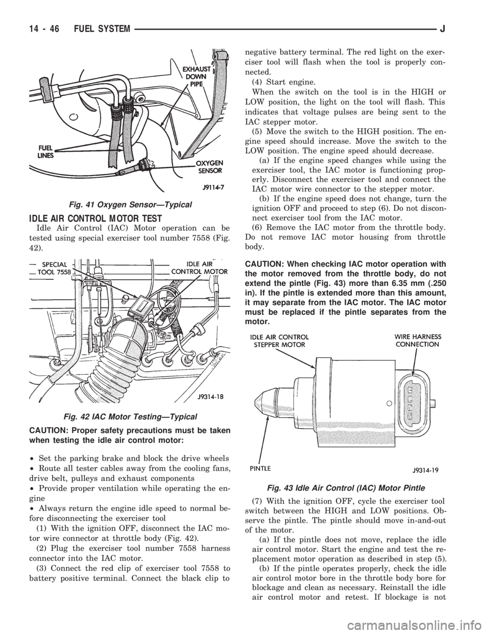
IDLE AIR CONTROL MOTOR TEST
Idle Air Control (IAC) Motor operation can be
tested using special exerciser tool number 7558 (Fig.
42).
CAUTION: Proper safety precautions must be taken
when testing the idle air control motor:
²Set the parking brake and block the drive wheels
²Route all tester cables away from the cooling fans,
drive belt, pulleys and exhaust components
²Provide proper ventilation while operating the en-
gine
²Always return the engine idle speed to normal be-
fore disconnecting the exerciser tool
(1) With the ignition OFF, disconnect the IAC mo-
tor wire connector at throttle body (Fig. 42).
(2) Plug the exerciser tool number 7558 harness
connector into the IAC motor.
(3) Connect the red clip of exerciser tool 7558 to
battery positive terminal. Connect the black clip tonegative battery terminal. The red light on the exer-
ciser tool will flash when the tool is properly con-
nected.
(4) Start engine.
When the switch on the tool is in the HIGH or
LOW position, the light on the tool will flash. This
indicates that voltage pulses are being sent to the
IAC stepper motor.
(5) Move the switch to the HIGH position. The en-
gine speed should increase. Move the switch to the
LOW position. The engine speed should decrease.
(a) If the engine speed changes while using the
exerciser tool, the IAC motor is functioning prop-
erly. Disconnect the exerciser tool and connect the
IAC motor wire connector to the stepper motor.
(b) If the engine speed does not change, turn the
ignition OFF and proceed to step (6). Do not discon-
nect exerciser tool from the IAC motor.
(6) Remove the IAC motor from the throttle body.
Do not remove IAC motor housing from throttle
body.
CAUTION: When checking IAC motor operation with
the motor removed from the throttle body, do not
extend the pintle (Fig. 43) more than 6.35 mm (.250
in). If the pintle is extended more than this amount,
it may separate from the IAC motor. The IAC motor
must be replaced if the pintle separates from the
motor.
(7) With the ignition OFF, cycle the exerciser tool
switch between the HIGH and LOW positions. Ob-
serve the pintle. The pintle should move in-and-out
of the motor.
(a) If the pintle does not move, replace the idle
air control motor. Start the engine and test the re-
placement motor operation as described in step (5).
(b) If the pintle operates properly, check the idle
air control motor bore in the throttle body bore for
blockage and clean as necessary. Reinstall the idle
air control motor and retest. If blockage is not
Fig. 41 Oxygen SensorÐTypical
Fig. 42 IAC Motor TestingÐTypical
Fig. 43 Idle Air Control (IAC) Motor Pintle
14 - 46 FUEL SYSTEMJ
Page 1016 of 1784
REMOVAL
(1) Disconnect the electrical connector from the
sensor.
(2) Remove the sensor from the intake manifold.
INSTALLATION
(1) Install the sensor into the intake manifold.
Tighten the sensor to 28 Nzm (20 ft. lbs.) torque.
(2) Connect the electrical connector to the sensor.
CRANKSHAFT POSITION SENSOR
For description, operation and removal/installation
procedures, refer to Group 8D, Ignition Systems in
this manual.
ENGINE COOLANT TEMPERATURE SENSOR
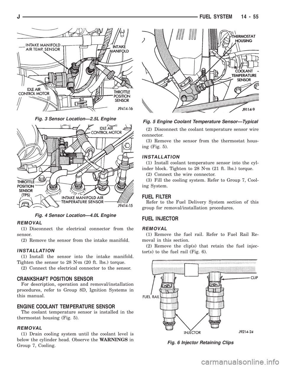
The coolant temperature sensor is installed in the
thermostat housing (Fig. 5).
REMOVAL
(1) Drain cooling system until the coolant level is
below the cylinder head. Observe theWARNINGSin
Group 7, Cooling.(2) Disconnect the coolant temperature sensor wire
connector.
(3) Remove the sensor from the thermostat hous-
ing (Fig. 5).
INSTALLATION
(1) Install coolant temperature sensor into the cyl-
inder block. Tighten to 28 Nzm (21 ft. lbs.) torque.
(2) Connect the wire connector.
(3) Fill the cooling system. Refer to Group 7, Cool-
ing System.
FUEL FILTER
Refer to the Fuel Delivery System section of this
group for removal/installation procedures.
FUEL INJECTOR
REMOVAL
(1) Remove the fuel rail. Refer to Fuel Rail Re-
moval in this section.
(2) Remove the clip(s) that retain the fuel injec-
tor(s) to the fuel rail (Fig. 6).
Fig. 3 Sensor LocationÐ2.5L Engine
Fig. 4 Sensor LocationÐ4.0L Engine
Fig. 5 Engine Coolant Temperature SensorÐTypical
Fig. 6 Injector Retaining Clips
JFUEL SYSTEM 14 - 55
Page 1039 of 1784
pump. The power steering pump is a constant flow
rate and displacement, vane-type pump. The internal
parts in the housing operate submerged in fluid. The
flow control orifice is part of the high pressure line
fitting. The pressure relief valve inside the flow con-
trol valve limits the pump pressure.
Power steering pumps have different pres-
sure rates and are not interchangeable with
other pumps.
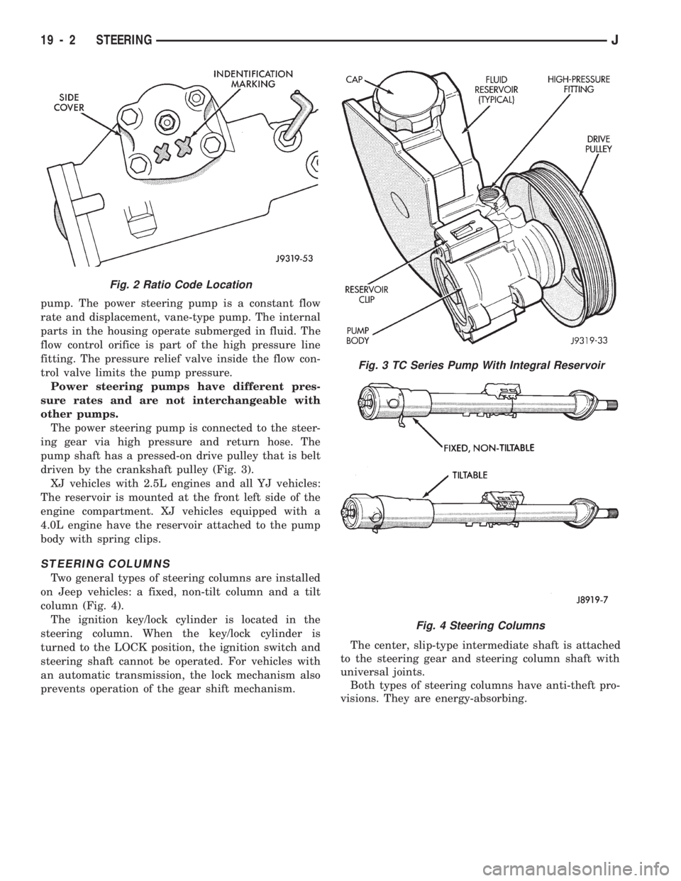
The power steering pump is connected to the steer-
ing gear via high pressure and return hose. The
pump shaft has a pressed-on drive pulley that is belt
driven by the crankshaft pulley (Fig. 3).
XJ vehicles with 2.5L engines and all YJ vehicles:
The reservoir is mounted at the front left side of the
engine compartment. XJ vehicles equipped with a
4.0L engine have the reservoir attached to the pump
body with spring clips.
STEERING COLUMNS
Two general types of steering columns are installed
on Jeep vehicles: a fixed, non-tilt column and a tilt
column (Fig. 4).
The ignition key/lock cylinder is located in the
steering column. When the key/lock cylinder is
turned to the LOCK position, the ignition switch and
steering shaft cannot be operated. For vehicles with
an automatic transmission, the lock mechanism also
prevents operation of the gear shift mechanism.The center, slip-type intermediate shaft is attached
to the steering gear and steering column shaft with
universal joints.
Both types of steering columns have anti-theft pro-
visions. They are energy-absorbing.
Fig. 3 TC Series Pump With Integral Reservoir
Fig. 4 Steering Columns
Fig. 2 Ratio Code Location
19 - 2 STEERINGJ
Page 1049 of 1784
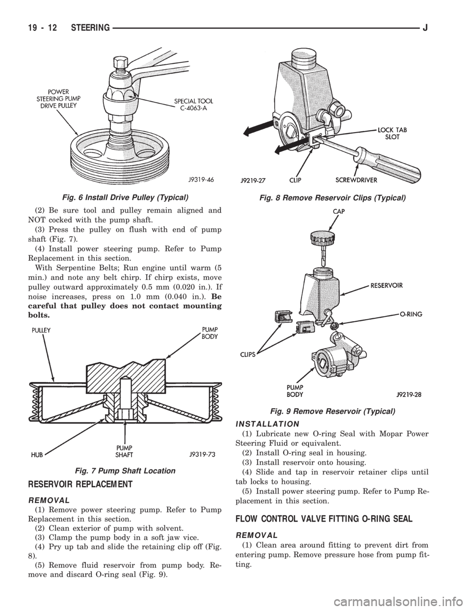
(2) Be sure tool and pulley remain aligned and
NOT cocked with the pump shaft.
(3) Press the pulley on flush with end of pump
shaft (Fig. 7).
(4) Install power steering pump. Refer to Pump
Replacement in this section.
With Serpentine Belts; Run engine until warm (5
min.) and note any belt chirp. If chirp exists, move
pulley outward approximately 0.5 mm (0.020 in.). If
noise increases, press on 1.0 mm (0.040 in.).Be
careful that pulley does not contact mounting
bolts.
RESERVOIR REPLACEMENT
REMOVAL
(1) Remove power steering pump. Refer to Pump
Replacement in this section.
(2) Clean exterior of pump with solvent.
(3) Clamp the pump body in a soft jaw vice.
(4) Pry up tab and slide the retaining clip off (Fig.
8).
(5) Remove fluid reservoir from pump body. Re-
move and discard O-ring seal (Fig. 9).
INSTALLATION
(1) Lubricate new O-ring Seal with Mopar Power
Steering Fluid or equivalent.
(2) Install O-ring seal in housing.
(3) Install reservoir onto housing.
(4) Slide and tap in reservoir retainer clips until
tab locks to housing.
(5) Install power steering pump. Refer to Pump Re-
placement in this section.
FLOW CONTROL VALVE FITTING O-RING SEAL
REMOVAL
(1) Clean area around fitting to prevent dirt from
entering pump. Remove pressure hose from pump fit-
ting.
Fig. 8 Remove Reservoir Clips (Typical)
Fig. 9 Remove Reservoir (Typical)
Fig. 6 Install Drive Pulley (Typical)
Fig. 7 Pump Shaft Location
19 - 12 STEERINGJ
Page 1050 of 1784
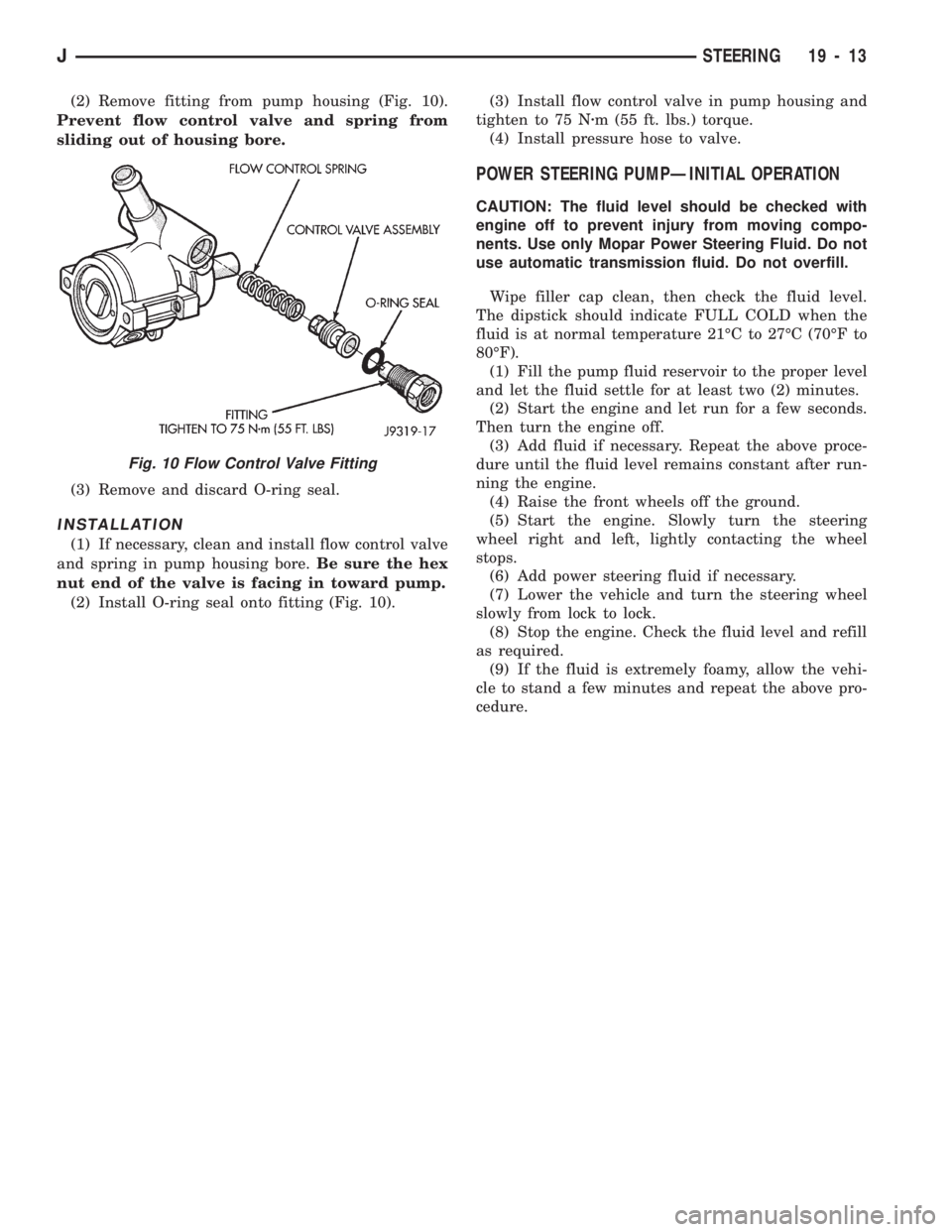
(2) Remove fitting from pump housing (Fig. 10).
Prevent flow control valve and spring from
sliding out of housing bore.
(3) Remove and discard O-ring seal.
INSTALLATION
(1) If necessary, clean and install flow control valve
and spring in pump housing bore.Be sure the hex
nut end of the valve is facing in toward pump.
(2) Install O-ring seal onto fitting (Fig. 10).(3) Install flow control valve in pump housing and
tighten to 75 Nzm (55 ft. lbs.) torque.
(4) Install pressure hose to valve.
POWER STEERING PUMPÐINITIAL OPERATION
CAUTION: The fluid level should be checked with
engine off to prevent injury from moving compo-
nents. Use only Mopar Power Steering Fluid. Do not
use automatic transmission fluid. Do not overfill.
Wipe filler cap clean, then check the fluid level.
The dipstick should indicate FULL COLD when the
fluid is at normal temperature 21ÉC to 27ÉC (70ÉF to
80ÉF).
(1) Fill the pump fluid reservoir to the proper level
and let the fluid settle for at least two (2) minutes.
(2) Start the engine and let run for a few seconds.
Then turn the engine off.
(3) Add fluid if necessary. Repeat the above proce-
dure until the fluid level remains constant after run-
ning the engine.
(4) Raise the front wheels off the ground.
(5) Start the engine. Slowly turn the steering
wheel right and left, lightly contacting the wheel
stops.
(6) Add power steering fluid if necessary.
(7) Lower the vehicle and turn the steering wheel
slowly from lock to lock.
(8) Stop the engine. Check the fluid level and refill
as required.
(9) If the fluid is extremely foamy, allow the vehi-
cle to stand a few minutes and repeat the above pro-
cedure.
Fig. 10 Flow Control Valve Fitting
JSTEERING 19 - 13
Page 1060 of 1784
²SECOND - over-center preload adjustment
WORM THRUST BEARING PRELOAD
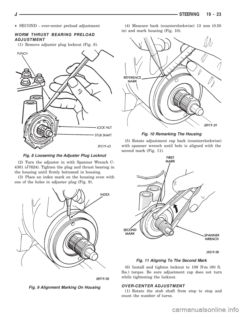
ADJUSTMENT
(1) Remove adjuster plug locknut (Fig. 8).
(2) Turn the adjuster in with Spanner Wrench C-
4381 (J7624). Tighten the plug and thrust bearing in
the housing until firmly bottomed in housing.
(3) Place an index mark on the housing even with
one of the holes in adjuster plug (Fig. 9).(4) Measure back (counterclockwise) 13 mm (0.50
in) and mark housing (Fig. 10).
(5) Rotate adjustment cap back (counterclockwise)
with spanner wrench until hole is aligned with the
second mark (Fig. 11).
(6) Install and tighten locknut to 109 Nzm (80 ft.
lbs.) torque. Be sure adjustment cap does not turn
while tightening the locknut.
OVER-CENTER ADJUSTMENT
(1) Rotate the stub shaft from stop to stop and
count the number of turns.
Fig. 10 Remarking The Housing
Fig. 11 Aligning To The Second Mark
Fig. 8 Loosening the Adjuster Plug Locknut
Fig. 9 Alignment Marking On Housing
JSTEERING 19 - 23
Page 1061 of 1784
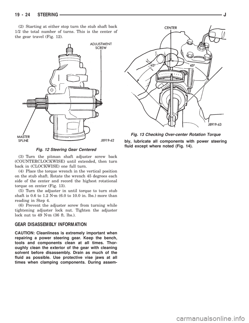
(2) Starting at either stop turn the stub shaft back
1/2 the total number of turns. This is the center of
the gear travel (Fig. 12).
(3) Turn the pitman shaft adjuster screw back
(COUNTERCLOCKWISE) until extended, then turn
back in (CLOCKWISE) one full turn.
(4) Place the torque wrench in the vertical position
on the stub shaft. Rotate the wrench 45 degrees each
side of the center and record the highest rotational
torque on center (Fig. 13).
(5) Turn the adjuster in until torque to turn stub
shaft is 0.6 to 1.2 Nzm (6.0 to 10.0 in. lbs.) more than
reading in Step 4.
(6) Prevent the adjuster screw from turning while
tightening adjuster lock nut. Tighten the adjuster
lock nut to 49 Nzm (36 ft. lbs.).
GEAR DISASSEMBLY INFORMATION
CAUTION: Cleanliness is extremely important when
repairing a power steering gear. Keep the bench,
tools and components clean at all times. Thor-
oughly clean the exterior of the gear with cleaning
solvent before disassembly. Drain as much of the
fluid as possible. Use protective vise jaws at all
times when clamping components. During assem-bly, lubricate all components with power steering
fluid except where noted (Fig. 14).
Fig. 13 Checking Over-center Rotation Torque
Fig. 12 Steering Gear Centered
19 - 24 STEERINGJ