1994 JEEP CHEROKEE tire pressure
[x] Cancel search: tire pressurePage 431 of 1784
(3) Move vehicle with the headlamps located di-
rectly above the 7.62-meters (25-feet) reference line.
(4) Equalize all the tire pressures.
(5) Rock vehicle from side to side to stabilize the
springs and shock absorbers.
(6) Use tape to attach a vehicle centerline on the
screen/wall (6). Ensure that it is aligned with and
represents the centerline of the vehicle.
(7) Measure distance between the vehicle head-
lamp centers. Divide this distance by two. Measure
the one/half distance outward from each side of the
vehicle centerline (6). Use tape to attach the right
and left lamp vertical centerline (4 and 5) on the
screen/wall (6).
(8) Measure the distance from the center of each
headlamp to the floor.
(9) Measure the lamp-to-floor distance upward
from the floor at each lamp vertical centerline (4 and
5). Use tape to attach the lamp horizontal centerline
(3) on the screen/wall.
ADJUSTMENT
(1) Remove screws and both headlamp bezels.
(2) Clean front of the headlamps.
(3) Place headlamps on LOW beam.
(4) Cover front of the headlamp that is not being
adjusted.
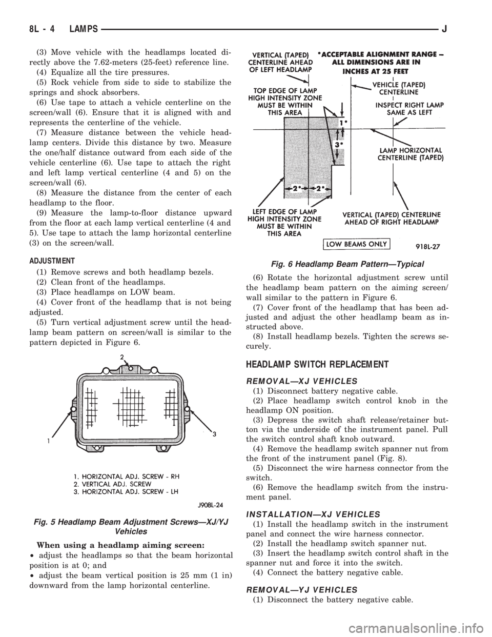
(5) Turn vertical adjustment screw until the head-
lamp beam pattern on screen/wall is similar to the
pattern depicted in Figure 6.
When using a headlamp aiming screen:
²adjust the headlamps so that the beam horizontal
position is at 0; and
²adjust the beam vertical position is 25 mm (1 in)
downward from the lamp horizontal centerline.(6) Rotate the horizontal adjustment screw until
the headlamp beam pattern on the aiming screen/
wall similar to the pattern in Figure 6.
(7) Cover front of the headlamp that has been ad-
justed and adjust the other headlamp beam as in-
structed above.
(8) Install headlamp bezels. Tighten the screws se-
curely.
HEADLAMP SWITCH REPLACEMENT
REMOVALÐXJ VEHICLES
(1) Disconnect battery negative cable.
(2) Place headlamp switch control knob in the
headlamp ON position.
(3) Depress the switch shaft release/retainer but-
ton via the underside of the instrument panel. Pull
the switch control shaft knob outward.
(4) Remove the headlamp switch spanner nut from
the front of the instrument panel (Fig. 8).
(5) Disconnect the wire harness connector from the
switch.
(6) Remove the headlamp switch from the instru-
ment panel.
INSTALLATIONÐXJ VEHICLES
(1) Install the headlamp switch in the instrument
panel and connect the wire harness connector.
(2) Install the headlamp switch spanner nut.
(3) Insert the headlamp switch control shaft in the
spanner nut and force it into the switch.
(4) Connect the battery negative cable.
REMOVALÐYJ VEHICLES
(1) Disconnect the battery negative cable.
Fig. 5 Headlamp Beam Adjustment ScrewsÐXJ/YJ
Vehicles
Fig. 6 Headlamp Beam PatternÐTypical
8L - 4 LAMPSJ
Page 440 of 1784
(1) Position the vehicle in dark area with a level
floor and with a screen (wall) that has a white sur-
face.
(2) Mark a reference line on the floor 7.62 meters
(25 feet) away from and parallel to the ``aiming''
screen/wall.
(3) Position vehicle with the fog lamps located di-
rectly above the 7.62-meters (25-feet) reference line.
(4) Equalize all the tire pressures.
(5) Rock the vehicle from side to side to stabilize
the springs and shock absorbers.
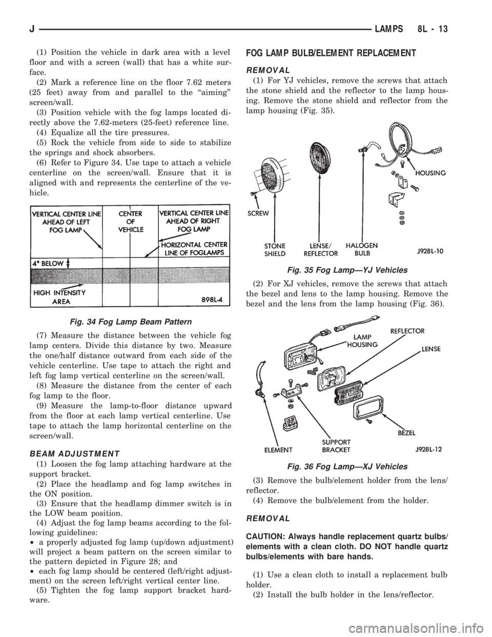
(6) Refer to Figure 34. Use tape to attach a vehicle
centerline on the screen/wall. Ensure that it is
aligned with and represents the centerline of the ve-
hicle.
(7) Measure the distance between the vehicle fog
lamp centers. Divide this distance by two. Measure
the one/half distance outward from each side of the
vehicle centerline. Use tape to attach the right and
left fog lamp vertical centerline on the screen/wall.
(8) Measure the distance from the center of each
fog lamp to the floor.
(9) Measure the lamp-to-floor distance upward
from the floor at each lamp vertical centerline. Use
tape to attach the lamp horizontal centerline on the
screen/wall.
BEAM ADJUSTMENT
(1) Loosen the fog lamp attaching hardware at the
support bracket.
(2) Place the headlamp and fog lamp switches in
the ON position.
(3) Ensure that the headlamp dimmer switch is in
the LOW beam position.
(4) Adjust the fog lamp beams according to the fol-
lowing guidelines:
²a properly adjusted fog lamp (up/down adjustment)
will project a beam pattern on the screen similar to
the pattern depicted in Figure 28; and
²each fog lamp should be centered (left/right adjust-
ment) on the screen left/right vertical center line.
(5) Tighten the fog lamp support bracket hard-
ware.
FOG LAMP BULB/ELEMENT REPLACEMENT
REMOVAL
(1) For YJ vehicles, remove the screws that attach
the stone shield and the reflector to the lamp hous-
ing. Remove the stone shield and reflector from the
lamp housing (Fig. 35).
(2) For XJ vehicles, remove the screws that attach
the bezel and lens to the lamp housing. Remove the
bezel and the lens from the lamp housing (Fig. 36).
(3) Remove the bulb/element holder from the lens/
reflector.
(4) Remove the bulb/element from the holder.
REMOVAL
CAUTION: Always handle replacement quartz bulbs/
elements with a clean cloth. DO NOT handle quartz
bulbs/elements with bare hands.
(1) Use a clean cloth to install a replacement bulb
holder.
(2) Install the bulb holder in the lens/reflector.
Fig. 34 Fog Lamp Beam Pattern
Fig. 35 Fog LampÐYJ Vehicles
Fig. 36 Fog LampÐXJ Vehicles
JLAMPS 8L - 13
Page 845 of 1784

CONNECTING ROD BEARING CLEARANCE
Engine connecting rod bearing clearances can be
determined by use of Plastigage, or equivalent. The
following is the recommended procedures for the use
of Plastigage:
(1) Remove oil film from surface to be checked.
Plastigage is soluble in oil.
(2) Place a piece of Plastigage across the entire
width of the bearing cap shell (Fig. 2). Position the
Plastigage approximately 6.35 mm (1/4 inch) off cen-
ter and away from the oil holes. In addition, suspect
areas can be checked by placing the Plastigage in the
suspect area.
(3) The crankshaft must be turned until the con-
necting rod to be checked starts moving toward the
top of the engine. Only then should the rod cap with
Plastigage in place be assembled. Tighten the rod
cap nut to 45 Nzm (33 ft. lbs.) torque.DO NOT ro-
tate the crankshaft or the Plastigage may be
smeared, giving inaccurate results.
(4) Remove the bearing cap and compare the width
of the flattened Plastigage with the scale provided on
the package (Fig. 3). Plastigage generally comes in 2
scales (one scale is in inches and the other is a met-
ric scale). Locate the band closest to the same width.
This band shows the amount of clearance. Differ-
ences in readings between the ends indicate the
amount of taper present. Record all readings taken
(refer to Engine Specifications).
(5) Plastigage is available in a variety of clearance
ranges. The 0.025-0.076 mm (0.001-0.003 inch) range
is usually the most appropriate for checking engine
bearing clearances.
REPAIR DAMAGED OR WORN THREADS
Damaged or worn threads can be repaired. Essen-
tially, this repair consists of:
²Drilling out worn or damaged threads.
²Tapping the hole with a special Heli-Coil Tap, or
equivalent.
²Installing an insert into the tapped hole.
This brings the hole back to its original thread size.
CAUTION: Be sure that the tapped holes maintain
the original center line.Heli-Coil tools and inserts are readily available
from automotive parts jobbers.
SERVICE ENGINE ASSEMBLY (SHORT BLOCK)
A service replacement engine assembly (short
block) may be installed whenever the original cylin-
der block is defective or damaged beyond repair. It
consists of the cylinder block, crankshaft, piston and
rod assemblies. If needed, the camshaft must be pro-
cured separately and installed before the engine is
installed in the vehicle.
A short block is identified with the letter ``S'' stamped
on the same machined surface where the build date
code is stamped for complete engine assemblies.
Installation includes the transfer of components
from the defective or damaged original engine. Fol-
low the appropriate procedures for cleaning, inspec-
tion and torque tightening.
HYDROSTATIC LOCK
When an engine is suspected of hydrostatic lock
(regardless of what caused the problem), follow the
steps below.
(1) Perform the Fuel Pressure Release Procedure
(refer to Group 14, Fuel System).
(2) Disconnect the negative cable from the battery.
(3) Inspect air cleaner, induction system and in-
take manifold to ensure system is dry and clear of
foreign material.
(4) Place a shop towel around the spark plugs to
catch any fluid that may possibly be under pressure in
the cylinder head. Remove the plugs from the engine.
CAUTION: DO NOT use the starter motor to rotate
the crankshaft. Severe damage could occur.
(5) With all spark plugs removed, rotate the crank-
shaft using a breaker bar and socket.
(6) Identify the fluid in the cylinders (i.e. coolant,
fuel, oil, etc.).
(7) Make sure all fluid has been removed from the
cylinders.
(8) Repair engine or components as necessary to
prevent this problem from occurring again.
(9) Squirt engine oil into the cylinders to lubricate
the walls. This will prevent damage on restart.
(10) Install new spark plugs. Tighten the spark
plugs to 37 Nzm (27 ft. lbs.) torque.
(11) Drain engine oil. Remove and discard the oil
filter.
(12) Install the drain plug. Tighten the plug to 34
Nzm (25 ft. lbs.) torque.
(13) Install a new oil filter.
(14) Fill engine crankcase with the specified
amount and grade of oil (refer to Group 0, Lubrica-
tion and Maintenance).
(15) Connect the negative cable to the battery.
(16) Start the engine and check for any leaks.
Fig. 3 Clearance Measurement
9 - 4 ENGINESJ
Page 951 of 1784

CONSTRUCTION
The frame is constructed of high-strength channel
steel siderails and crossmembers. The crossmembers
join the siderails and retain them in alignment in re-
lation to each other. This provides resistance to
frame twists and strains.
FRAME ALIGNMENT
INCORRECT ALIGNMENT
Incorrect frame alignment is usually a result of:
²collision impact, or
²the vehicle being operated with excessive loads, or
²loads not positioned in a properly distributed man-
ner on the vehicle.
A mis-aligned frame will affect front axle and/or
rear axle alignment. It can cause excessive wear and
mechanical failures in the powertrain. Window glass
cracks and door opening/closing problems. Vehicle
performance can also be impaired.
RE-ALIGNMENT
With collision damage, it is important that the ex-
istence of any frame alignment damage be deter-
mined. If necessary, the frame should be correctly re-
aligned. Refer to the reference dimensions listed on
frame alignment dimension chart (Fig. 4).
FRAME INSPECTION/MEASUREMENTS
INSPECTION
Before proceeding with measurements, inspect all
components for visible damage and other metal dam-
age. Also, inspect all connections for loose and miss-
ing hardware.
All damaged areas must be repaired and/or the
components replaced, as necessary.
MEASUREMENTS
Measure the frame for mis-alignment with the
body attached to the frame. Figure 4 provides the
alignment reference dimensions. The following infor-
mation applies to all measurements.
(1) Place the vehicle on a level surface.
(2) If the vehicle is loaded, ensure that the vehicle
weight plus the payload does not exceed the gross ve-
hicle weight rating. Also, ensure that the load is dis-
tributed in the vehicle as evenly as possible.
(3) Measure the tire inflation pressures and adjust
the pressure, if necessary.
HORIZONTAL OR DIAGONAL FRAME MEASUREMENTS
Determine the frame horizontal non-square devia-
tion(s) according to the following procedure.
(1) Select several reference points along one frame
siderail, preferably at the crossmember junctions.(2) Transfer these reference points to the surface/
floor with a plumb bob. Paper sheets can be attached
to the surface below the reference points for better
measurement accuracy.
(3) Locate the reference points on the other frame
siderail and transfer them to the surface/floor with
the same procedure as above.
(4) Move the vehicle away and measure between
all the reference points diagonally from and parallel
to the siderails (Fig. 5). The measurements should
not differ by more than 6 mm (1/4 in).
(5) Measure the distance between the two front
reference points and the distance between the two
rear reference points. Divide each distance in half
and indicate the two half-way points on the surface/
floor. Designate the front point as ``1'' and the rear
point as ``2'' (Fig. 5).
(6) Place a chalk-line between points 1 and 2 and
``snap'' the string.
(7) Determine how close the center line is to the
diagonal intersection points A, B, C, D, E, and F in
Figure 5.
(8) The reference marks on the surface/floor will
provide an illustrated indication of the degree of
frame misalignment.
(9) A reference point transferred from one frame
siderail may be 3 mm (1/8 in) ahead or behind the
reference point from the opposite siderail.
(10) Frame bow to the side should not exceed 3
mm per 2,540 mm (1/8 inch per 100 inches) in
length.
(11) The overall width of the frame should not
vary more than 3 mm (1/8 in) from reference point-
to-reference point.
(12) Repeat steps (1) through (11) after straighten-
ing the frame to evaluate the effectiveness.
TWIST AND PARALLEL FRAME MEASUREMENTS
Determine the amount of frame twist and siderail
deviation according to the following procedure.
(1) Mark the vertical measurement reference
points under the frame siderails at 305-mm (12-in)
intervals starting at the rear frame crossmember.
(2) Measure the vertical distance up from a level
surface to each reference point located under the left
and right frame siderails.
(3) The distance to a reference point under one
frame siderail should be 3 mm (1/8 in) greater or less
than the point under the opposite siderail.
(4) Plot the measured vertical distances to scale on
a sheet of graph paper. Plot the distances so that the
frame siderails are located adjacent to each other.
Join the vertical distance points.
13 - 10 FRAME AND BUMPERSJ
Page 1028 of 1784
²Have a 3 degree maximum operating angle
²Have at least a 1/2 degree continuous operating
(propeller shaft) angle
Engine speed (R.P.M.) is the main factor though in
determining maximum allowable operating angles.
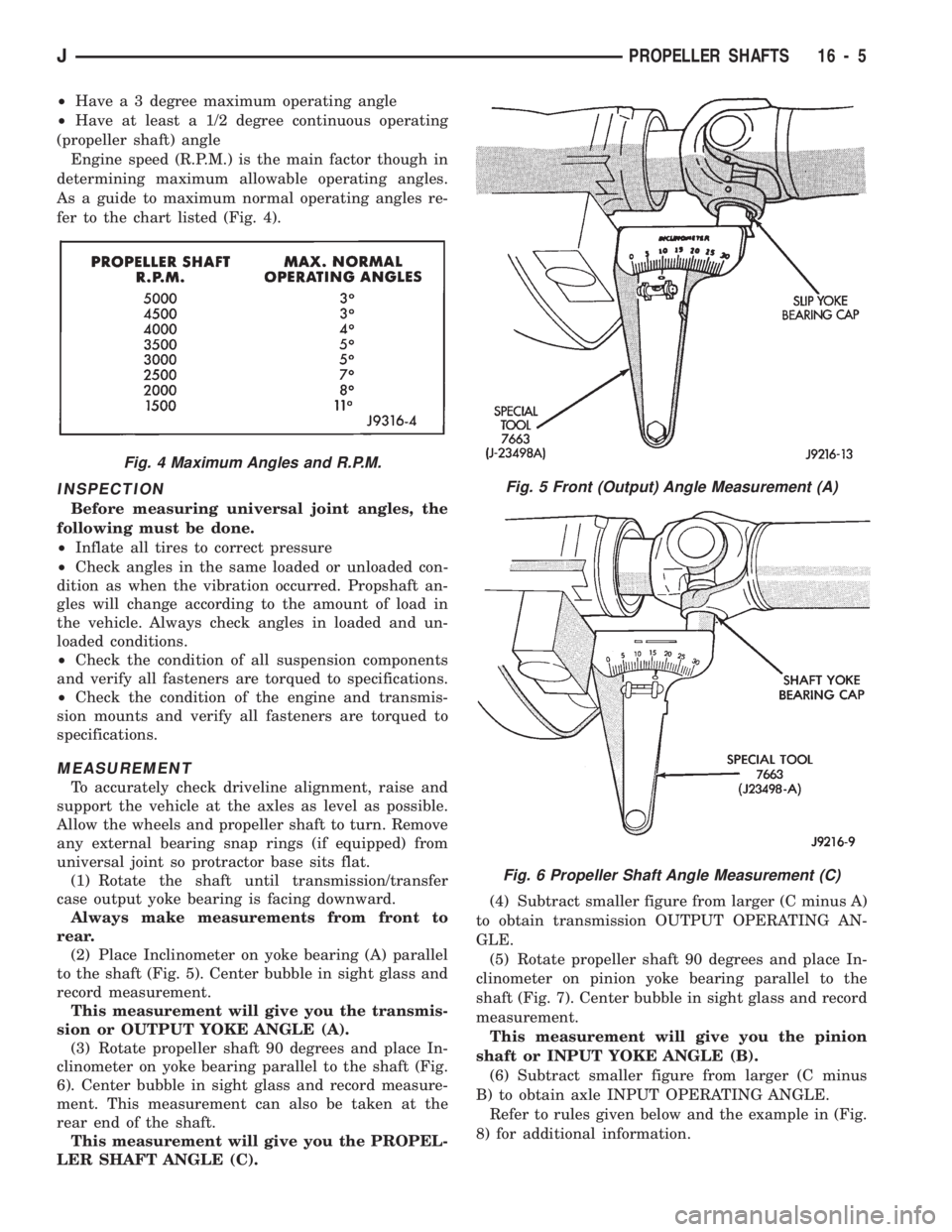
As a guide to maximum normal operating angles re-
fer to the chart listed (Fig. 4).
INSPECTION
Before measuring universal joint angles, the
following must be done.
²Inflate all tires to correct pressure
²Check angles in the same loaded or unloaded con-
dition as when the vibration occurred. Propshaft an-
gles will change according to the amount of load in
the vehicle. Always check angles in loaded and un-
loaded conditions.
²Check the condition of all suspension components
and verify all fasteners are torqued to specifications.
²Check the condition of the engine and transmis-
sion mounts and verify all fasteners are torqued to
specifications.
MEASUREMENT
To accurately check driveline alignment, raise and
support the vehicle at the axles as level as possible.
Allow the wheels and propeller shaft to turn. Remove
any external bearing snap rings (if equipped) from
universal joint so protractor base sits flat.
(1) Rotate the shaft until transmission/transfer
case output yoke bearing is facing downward.
Always make measurements from front to
rear.
(2) Place Inclinometer on yoke bearing (A) parallel
to the shaft (Fig. 5). Center bubble in sight glass and
record measurement.
This measurement will give you the transmis-
sion or OUTPUT YOKE ANGLE (A).
(3) Rotate propeller shaft 90 degrees and place In-
clinometer on yoke bearing parallel to the shaft (Fig.
6). Center bubble in sight glass and record measure-
ment. This measurement can also be taken at the
rear end of the shaft.
This measurement will give you the PROPEL-
LER SHAFT ANGLE (C).(4) Subtract smaller figure from larger (C minus A)
to obtain transmission OUTPUT OPERATING AN-
GLE.
(5) Rotate propeller shaft 90 degrees and place In-
clinometer on pinion yoke bearing parallel to the
shaft (Fig. 7). Center bubble in sight glass and record
measurement.
This measurement will give you the pinion
shaft or INPUT YOKE ANGLE (B).
(6) Subtract smaller figure from larger (C minus
B) to obtain axle INPUT OPERATING ANGLE.
Refer to rules given below and the example in (Fig.
8) for additional information.
Fig. 4 Maximum Angles and R.P.M.
Fig. 5 Front (Output) Angle Measurement (A)
Fig. 6 Propeller Shaft Angle Measurement (C)
JPROPELLER SHAFTS 16 - 5
Page 1218 of 1784
Fitting And Cooler Line Service
The cooler lines and quick disconnect fittings are
NOT serviceable. Damaged fittings or cooler lines
are to be replaced as assemblies.
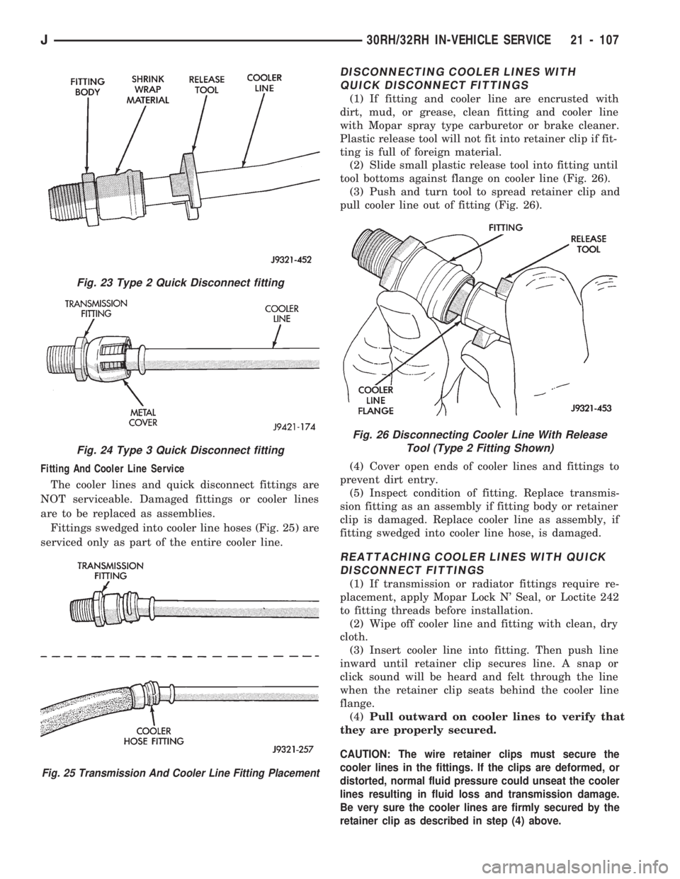
Fittings swedged into cooler line hoses (Fig. 25) are
serviced only as part of the entire cooler line.
DISCONNECTING COOLER LINES WITH
QUICK DISCONNECT FITTINGS
(1) If fitting and cooler line are encrusted with
dirt, mud, or grease, clean fitting and cooler line
with Mopar spray type carburetor or brake cleaner.
Plastic release tool will not fit into retainer clip if fit-
ting is full of foreign material.
(2) Slide small plastic release tool into fitting until
tool bottoms against flange on cooler line (Fig. 26).
(3) Push and turn tool to spread retainer clip and
pull cooler line out of fitting (Fig. 26).
(4) Cover open ends of cooler lines and fittings to
prevent dirt entry.
(5) Inspect condition of fitting. Replace transmis-
sion fitting as an assembly if fitting body or retainer
clip is damaged. Replace cooler line as assembly, if
fitting swedged into cooler line hose, is damaged.
REATTACHING COOLER LINES WITH QUICK
DISCONNECT FITTINGS
(1) If transmission or radiator fittings require re-
placement, apply Mopar Lock N' Seal, or Loctite 242
to fitting threads before installation.
(2) Wipe off cooler line and fitting with clean, dry
cloth.
(3) Insert cooler line into fitting. Then push line
inward until retainer clip secures line. A snap or
click sound will be heard and felt through the line
when the retainer clip seats behind the cooler line
flange.
(4)Pull outward on cooler lines to verify that
they are properly secured.
CAUTION: The wire retainer clips must secure the
cooler lines in the fittings. If the clips are deformed, or
distorted, normal fluid pressure could unseat the cooler
lines resulting in fluid loss and transmission damage.
Be very sure the cooler lines are firmly secured by the
retainer clip as described in step (4) above.
Fig. 23 Type 2 Quick Disconnect fitting
Fig. 24 Type 3 Quick Disconnect fitting
Fig. 25 Transmission And Cooler Line Fitting Placement
Fig. 26 Disconnecting Cooler Line With Release
Tool (Type 2 Fitting Shown)
J30RH/32RH IN-VEHICLE SERVICE 21 - 107
Page 1242 of 1784
(11) Install first clutch disc in retainer on top of
bottom pressure plate. Then install a clutch plate fol-
lowed by a clutch disc until entire clutch pack is in-
stalled.
²3 discs and 2 plates are used in 30RH (Fig. 65)
²4 discs and 3 plates are required in 32RH (Fig.
66).
(12) Install top pressure plate (Figs. 65-66).
(13) Install selective snap ring (Figs. 65-66). Be
sure snap ring is fully seated in retainer groove.
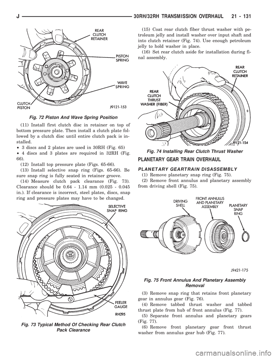
(14) Measure clutch pack clearance (Fig. 73).
Clearance should be 0.64 - 1.14 mm (0.025 - 0.045
in.). If clearance is incorrect, steel plates, discs, snap
ring and pressure plates may have to be changed.(15) Coat rear clutch fiber thrust washer with pe-
troleum jelly and install washer over input shaft and
into clutch retainer (Fig. 74). Use enough petroleum
jelly to hold washer in place.
(16) Set rear clutch aside for installation during fi-
nal assembly.
PLANETARY GEAR TRAIN OVERHAUL
PLANETARY GEARTRAIN DISASSEMBLY
(1) Remove planetary snap ring (Fig. 75).
(2) Remove front annulus and planetary assembly
from driving shell (Fig. 75).
(3) Remove snap ring that retains front planetary
gear in annulus gear (Fig. 76).
(4) Remove tabbed thrust washer and tabbed
thrust plate from hub of front annulus (Fig. 77).
(5) Separate front annulus and planetary gears
(Fig. 77).
(6) Remove front planetary gear front thrust
washer from annulus gear hub (Fig. 77).
Fig. 72 Piston And Wave Spring Position
Fig. 73 Typical Method Of Checking Rear Clutch
Pack Clearance
Fig. 74 Installing Rear Clutch Thrust Washer
Fig. 75 Front Annulus And Planetary Assembly
Removal
J30RH/32RH TRANSMISSION OVERHAUL 21 - 131
Page 1444 of 1784
WHEELS AND TIRES
CONTENTS
page page
SPECIFICATIONS....................... 11
TIRES................................. 1VEHICLE VIBRATION..................... 9
WHEELS............................... 6
TIRES
INDEX
page page
Cleaning of Tires.......................... 2
General Information........................ 1
Pressure Gauges......................... 2
Repairing Leaks.......................... 3
Replacement Tires........................ 2Rotation................................ 3
Tire Inflation Pressures..................... 2
Tire Noise or Vibration..................... 4
Tire Wear Patterns........................ 4
Tread Wear Indicators...................... 3
GENERAL INFORMATION
Tires are designed for each specific vehicle. They
provide the best overall performance for normal op-
eration. The ride and handling characteristics match
the vehicle's requirements. With proper care they
will give excellent reliability, traction, skid resis-
tance, and tread life. These tires have specific load
carrying capacities. When correctly inflated, they
will operate properly.
Tires used in cool climates, and with light loads
will have a longer life than tires used in hot climates
with heavy loads. Abrasive road surfaces will accel-
erate tire wear.
Driving habits have more effect on tire life than
any other factor. Careful drivers will obtain much
greater mileage than careless drivers.
Driving habits that shorten the life of any tire;
²Rapid acceleration and deceleration
²Severe application of brakes
²High-speed driving
²Taking turns at excessive speeds
²Striking curbs and other obstacles
It is very important to follow the tire rotation in-
terval
IDENTIFICATION
Tire type, size, aspect ratio and speed rating are
encoded in the letters and numbers imprinted on the
side wall of the tire. Refer to the chart to decipher
the tire identification code (Fig. 1).
Performance tires will have a speed rating letter
after the aspect ratio number. The speed rating isnot always printed on the tire sidewall. The letterS
indicates that the tire is speed rated up to 112 mph.
²Qup to 100 mph
²Tup to 118 mph
²Uup to 124 mph
²Hup to 130 mph
²Vup to 149 mph
²Zmore than 149 mph (consult the tire manufac-
turer for the specific speed rating)
An All Season type tire will have eitherM+S,M
&SorMÐS(indicating mud and snow traction) im-
printed on the side wall.
RADIAL-PLY TIRES
Radial-ply tires improve handling, tread life, ride
quality and decrease rolling resistance.
Radial-ply tires must always be used in sets of
four. Under no circumstances should they be used on
the front only. They may be mixed with temporary
spare tires when necessary, but reduced speeds are
recommended.
Radial-ply tires have the same load-carrying capac-
ity as other types of tires of the same size. They use
the same recommended inflation pressures.
SPARE TIRE (TEMPORARY)
The compact spare tire is designed for emergency
use only. The original tire should be repaired and re-
installed at the first opportunity. Refer to Owner's
Manual for complete details.
JWHEELS AND TIRES 22 - 1