1994 JEEP CHEROKEE Ac control
[x] Cancel search: Ac controlPage 3 of 1784
ROUTINE SERVICE
The following routine vehicle service is highly rec-
ommended on a monthly basis.
TIRESÐInspect the tires for unusual wear/damage
and determine if the inflation pressure is acceptable
for the vehicle load.
BATTERYÐInspect and clean the terminals.
Tighten the terminals, if necessary.
FLUIDSÐDetermine if the coolant, brake fluid,
power steering, automatic transmission, and clutch
fluid level are acceptable. Add fluid, if necessary.
LIGHTS/ELECTRICALÐTest all the electrically
operated systems in the vehicle for proper operation.
It is also recommended that the engine oil level
and the windshield washer fluid level be deter-
mined (and corrected) during each fuel fill-up.
FUEL REQUIREMENTS
All Jeeptengines require the use of unleaded gas-
oline. In addition, the fuel must have a minimum oc-
tane rating of 87.
CAUTION: UNLEADED FUEL ONLY must be used in
vehicles equipped with a catalyst emission control
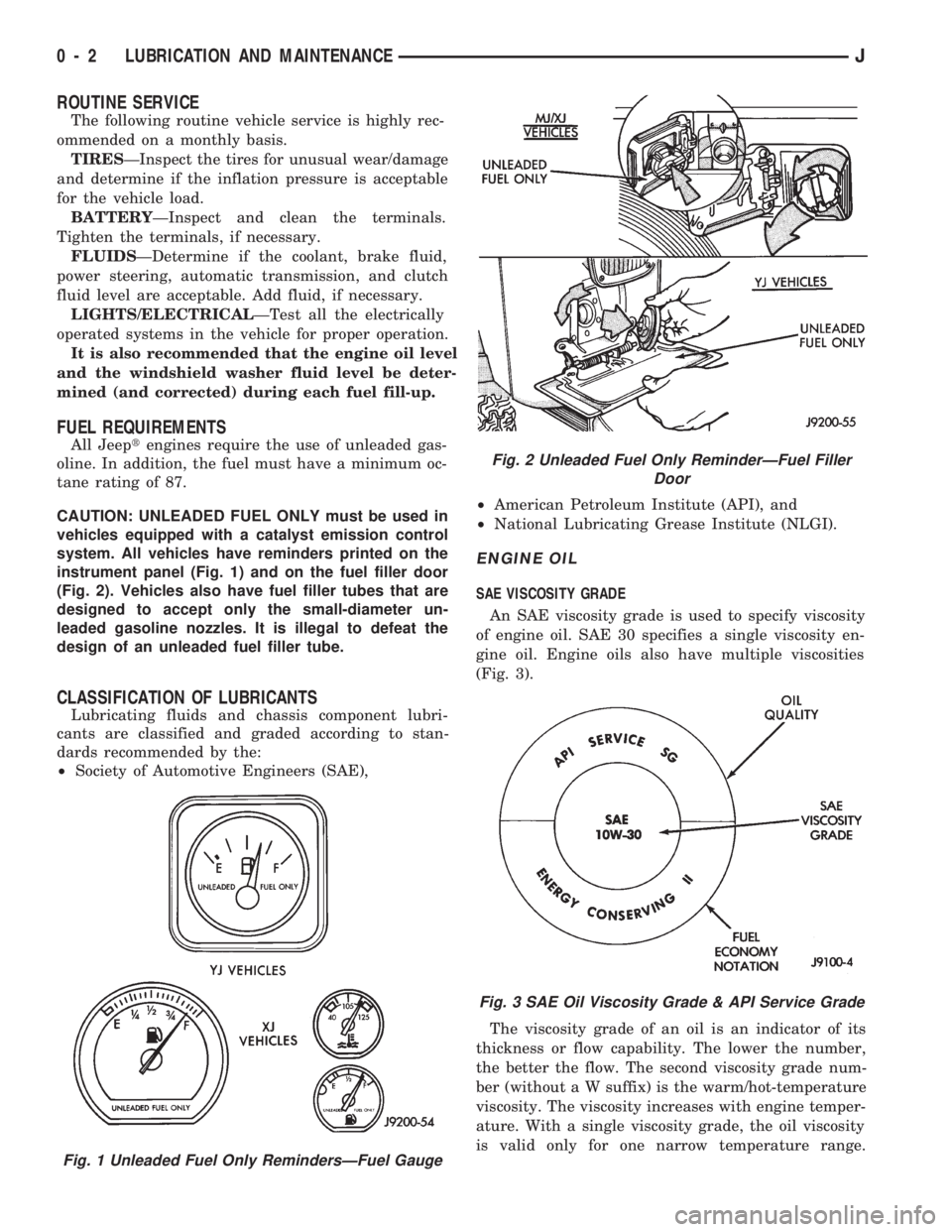
system. All vehicles have reminders printed on the
instrument panel (Fig. 1) and on the fuel filler door
(Fig. 2). Vehicles also have fuel filler tubes that are
designed to accept only the small-diameter un-
leaded gasoline nozzles. It is illegal to defeat the
design of an unleaded fuel filler tube.
CLASSIFICATION OF LUBRICANTS
Lubricating fluids and chassis component lubri-
cants are classified and graded according to stan-
dards recommended by the:
²Society of Automotive Engineers (SAE),²American Petroleum Institute (API), and
²National Lubricating Grease Institute (NLGI).
ENGINE OIL
SAE VISCOSITY GRADE
An SAE viscosity grade is used to specify viscosity
of engine oil. SAE 30 specifies a single viscosity en-
gine oil. Engine oils also have multiple viscosities
(Fig. 3).
The viscosity grade of an oil is an indicator of its
thickness or flow capability. The lower the number,
the better the flow. The second viscosity grade num-
ber (without a W suffix) is the warm/hot-temperature
viscosity. The viscosity increases with engine temper-
ature. With a single viscosity grade, the oil viscosity
is valid only for one narrow temperature range.
Fig. 1 Unleaded Fuel Only RemindersÐFuel Gauge
Fig. 2 Unleaded Fuel Only ReminderÐFuel Filler
Door
Fig. 3 SAE Oil Viscosity Grade & API Service Grade
0 - 2 LUBRICATION AND MAINTENANCEJ
Page 4 of 1784
Above that temperature range the viscosity will de-
crease, and below that range the viscosity will in-
crease.
An engine oil with an SAE 5W-30 viscosity grade
provides good flow capability for fast cold weather
engine starts. The viscosity will then increase with
engine temperature to provide good high-tempera-
ture engine lubrication.
API SERVICE GRADE
The API Service Grade specifies the type of engine/
operating conditions for which the oil is intended.
The API Service Grade specifications also apply to
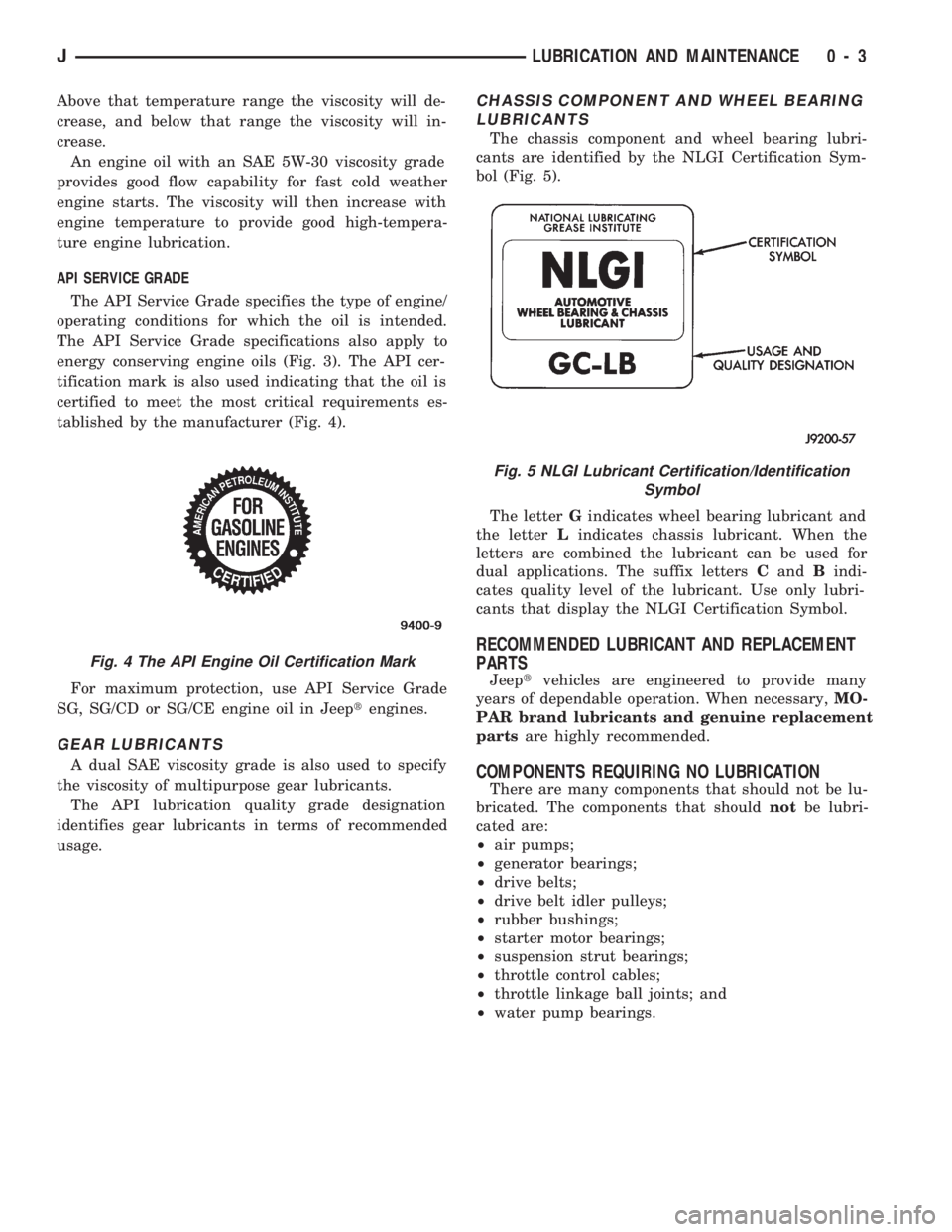
energy conserving engine oils (Fig. 3). The API cer-
tification mark is also used indicating that the oil is
certified to meet the most critical requirements es-
tablished by the manufacturer (Fig. 4).
For maximum protection, use API Service Grade
SG, SG/CD or SG/CE engine oil in Jeeptengines.
GEAR LUBRICANTS
A dual SAE viscosity grade is also used to specify
the viscosity of multipurpose gear lubricants.
The API lubrication quality grade designation
identifies gear lubricants in terms of recommended
usage.
CHASSIS COMPONENT AND WHEEL BEARING
LUBRICANTS
The chassis component and wheel bearing lubri-
cants are identified by the NLGI Certification Sym-
bol (Fig. 5).
The letterGindicates wheel bearing lubricant and
the letterLindicates chassis lubricant. When the
letters are combined the lubricant can be used for
dual applications. The suffix lettersCandBindi-
cates quality level of the lubricant. Use only lubri-
cants that display the NLGI Certification Symbol.
RECOMMENDED LUBRICANT AND REPLACEMENT
PARTS
Jeeptvehicles are engineered to provide many
years of dependable operation. When necessary,MO-
PAR brand lubricants and genuine replacement
partsare highly recommended.
COMPONENTS REQUIRING NO LUBRICATION
There are many components that should not be lu-
bricated. The components that shouldnotbe lubri-
cated are:
²air pumps;
²generator bearings;
²drive belts;
²drive belt idler pulleys;
²rubber bushings;
²starter motor bearings;
²suspension strut bearings;
²throttle control cables;
²throttle linkage ball joints; and
²water pump bearings.
Fig. 4 The API Engine Oil Certification Mark
Fig. 5 NLGI Lubricant Certification/Identification
Symbol
JLUBRICATION AND MAINTENANCE 0 - 3
Page 19 of 1784

In areas of the country where carbon monoxide lev-
els are high, gasolines are being treated with oxy-
genated materials such as MTBE, ETBE and
ethanol.
Chrysler Corporation supports these efforts toward
cleaner air and recommends the use of these gaso-
lines as they become available.
IGNITION CABLES, DISTRIBUTOR CAP AND
ROTOR
REQUIRED IGNITION SYSTEM MAINTENANCE
The ignition cables, distributor cap and rotor must
be replaced after each 96 000-km (60,000-miles). Re-
fer to Group 8DÐIgnition Systems for additional in-
formation.
IGNITION TIMING
The ignition timing for 2.5L and 4.0L engines is
not adjustable. Refer to the specifications listed on
the engine Emission Control Information Label. Re-
fer to Group 25ÐEmission Control Systems for addi-
tional information.
SPARK PLUGS
REQUIRED MAINTENANCE
The spark plugs must be replaced after each 48
000-km (30,000-miles). Refer to the Spark Plugs
chart below and to Group 8DÐIgnition Systems for
additional information.
BATTERY
RECOMMENDED MAINTENANCE
The battery electrolyte level should be checked and
the cable clamps should be inspected for corrosion.
This should be done when the oil is changed and the
oil filter is replaced.
The battery cables should be inspected for abnor-
mal clamp and battery terminal post corrosion. Ser-
vice the terminals and cable clamps as necessary.In addition, the general condition of the battery
should be determined before the start of cold and hot
weather seasons. If the battery condition is marginal
or worse, it should be replaced.
Care should be taken when disposing a bat-
tery after removal from a vehicle. Lead-acid bat-
teries are highly poisonous and, when
indiscriminately disposed, could create a prob-
lem for the environment. Contact the applicable
local city or county government agency to deter-
mine where automobile (lead-acid) batteries can
be properly disposed in the local area.
INSPECTION/SERVICE
WARNING: WEAR SAFETY GLASSES, RUBBER
GLOVES AND PROTECTIVE CLOTHING WHEN HAN-
DLING/SERVICING A BATTERY. THE BATTERY
ELECTROLYTE CONTAINS SULFURIC ACID AND
WILL CAUSE HARM IF IT CONTACTS SKIN, EYES
OR CLOTHING. IT WILL ALSO DAMAGE PAINTED
(AS WELL AS UN-PAINTED) SURFACES OF A VEHI-
CLE. IF SULFURIC ACID CONTACTS ANY OF
THESE, FLUSH IMMEDIATELY WITH LARGE
AMOUNTS OF WATER. IF SULFURIC ACID CON-
TACTS SKIN OR EYES, GET IMMEDIATE MEDICAL
ATTENTION. DO NOT SMOKE IN THE VICINITY OF
A BATTERY. KEEP OPEN FLAMES AND SPARKS
AWAY FROM BATTERY FILLER CAPS BECAUSE
EXPLOSIVE GAS IS ALWAYS PRESENT.
(1) Disconnect the battery negative cable and then
the positive cable.
(2) Clean the battery cable clamps and terminal
posts with a wire brush and a battery terminal
cleaner.
(3) Pry the battery cell filler caps upward to re-
move them and inspect each filler well (low-mainte-
nance batteries only, not applicable to maintenance-
free batteries). It could possibly be necessary to
loosen the battery holddown clamp to remove the
caps. Maintain the electrolyte level above the battery
plates and at the bottom of the filler well ring. Add
distilled water or low-mineral content drinking wa-
ter, if necessary. In freezing weather (below 0ÉC/
32ÉF), add the water just before driving to ensure
that it mixes thoroughly with the electrolyte. This
will prevent it from freezing.
(4) Remove the battery holddown strap and clean
the battery case/battery tray.Clean with bicarbonate
of soda (baking soda) and water. Rinse and dry the
battery case/tray thoroughly after cleaning.
(5) Position the battery in the tray and install the
holddown strap.Do not over-tighten the nuts.
(6) Connect the battery positive cable and then the
negative cable to the battery.
SPARK PLUGS
0 - 18 LUBRICATION AND MAINTENANCEJ
Page 20 of 1784
(7) Apply a small amount of chassis lubricant (or
an equivalent protective coating) to the cable termi-
nals to minimize corrosion.
RUBBER AND PLASTIC DUCTS/HOSES/TUBING
RECOMMENDED MAINTENANCE
Rubber and plastic ducts/hoses/tubing should be in-
spected at the same time the engine oil is changed
and the oil filter is replaced.
The conditions associated with vehicle operation
determines the usable life of the rubber and plastic
ducts/hoses/tubing. These conditions include:
²the extent and quality of vehicle maintenance,
²the geographic area of vehicle operation, and
²the length of exposure time to excess heat and
chemical contaminants.
DUCT/HOSE/TUBING INSPECTIONÐEXCEPT
EMISSION CONTROL HOSES/TUBING
Refer to Group 25ÐEmission Control Systems.
Engine performance could be affected by air leaks
into various hoses.
Rubber/plastic ducts, hoses and tubing should
be replaced immediately if there is any evidence
of deterioration.
(1) Inspect all hose fittings for looseness and corro-
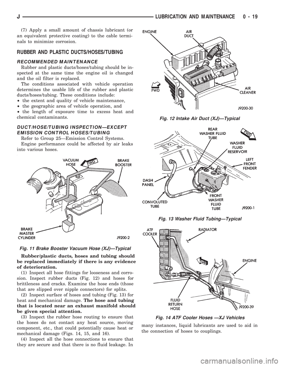
sion. Inspect rubber ducts (Fig. 12) and hoses for
brittleness and cracks. Examine the hose ends (those
that are slipped over nipple connectors) for splits.
(2) Inspect surface of hoses and tubing (Fig. 13) for
heat and mechanical damage.The hose and tubing
that is located near an exhaust manifold should
be given special attention.
(3) Inspect the rubber hose routing to ensure that
the hoses do not contact any heat source, moving
component, etc., that could potentially cause heat or
mechanical damage (Figs. 14, 15, and 16).
(4) Inspect all the hose connections to ensure that
they are secure and that there is no fluid leakage. Inmany instances, liquid lubricants are used to aid in
the connection of hoses to couplings.
Fig. 12 Intake Air Duct (XJ)ÐTypical
Fig. 13 Washer Fluid TubingÐTypical
Fig. 14 ATF Cooler Hoses ÐXJ Vehicles
Fig. 11 Brake Booster Vacuum Hose (XJ)ÐTypical
JLUBRICATION AND MAINTENANCE 0 - 19
Page 39 of 1784
axle assembly to the frame. The lower arms uses
shims at the frame mount to allow for adjustment of
caster and pinion angle. The suspension arm travel
(jounce or rebound) is limited through the use of rub-
ber bumpers.
Suspension components which use rubber bushings
should be tightened at vehicle ride height. This will
prevent premature failure of the bushing and main-
tain ride comfort. Bushings must never be lubricated.
The coil springs control ride quality and maintain
proper ride height. The coil springs mount up in the
fender shield which is part of the unitized body
bracket. A rubber isolator is located between the top
of the spring and the frame. The bottom of the spring
seats on a axle pad and is retained with a clip.
The shock absorbers dampen jounce and rebound of
the vehicle over various road conditions. The top of
the shock absorbers are bolted to the frame. The bot-
tom of the shocks are bolted to the axle spring
bracket.
The stabilizer bar is used to minimize vehicle front
sway during turns. The spring steel bar helps to con-
trol the vehicle body in relationship to the suspen-
sion. The bar extends across the front underside of
the chassis and connects to the frame rails. Links are
connected from the bar to the axle brackets. Stabi-
lizer bar mounts are isolated by rubber bushings.
The track bar is used to minimize front axle side-
to-side movement. The bar is attached to a frame rail
bracket with a ball stud and isolated with a bushing
at the axle bracket.
TUBE AXLE (2WD VEHICLES)
The front axle used on two-wheel drive vehicles is
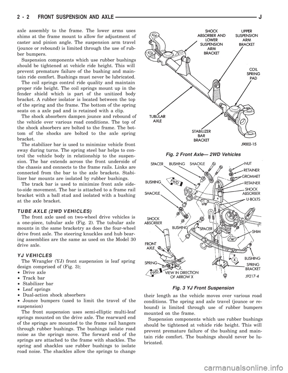
a one-piece, tubular axle (Fig. 2). The tubular axle
mounts in the same bracketry as does the four-wheel
drive front axle. The steering knuckles and hub bear-
ing assemblies are the same as used on the Model 30
drive axle.
YJ VEHICLES
The Wrangler (YJ) front suspension is leaf spring
design comprised of (Fig. 3);
²Drive axle
²Track bar
²Stabilizer bar
²Leaf springs
²Dual-action shock absorbers
²Jounce bumpers (used to limit the travel of the
suspension)
The front suspension uses semi-elliptic multi-leaf
springs mounted on the drive axle. The rearward end
of the springs are mounted to the frame rail hangers
through rubber bushings. The bushings isolate road
noise as the springs move. The forward end of the
springs are attached to the frame with shackles. The
spring and shackles use rubber bushings to isolate
road noise. The shackles allow the springs to changetheir length as the vehicle moves over various road
conditions. The spring and axle travel (jounce or re-
bound) is limited through use of rubber bumpers
mounted on the frame.
Suspension components which use rubber bushings
should be tightened at vehicle ride height. This will
prevent premature failure of the bushing and main-
tain ride comfort. The bushings should never be lu-
bricated.
Fig. 2 Front AxleÐ 2WD Vehicles
Fig. 3 YJ Front Suspension
2 - 2 FRONT SUSPENSION AND AXLEJ
Page 63 of 1784
(3) Place the socket (driver) against one bearing
cap. Position the yoke with the socket wrench in a
vise.
(4) Compress the vise to force the bearing caps into
the yoke. Force the caps enough to install the retain-
ing clips.
(5) Install the bearing cap retaining clips.
(6) Install the axle shaft, refer to Hub Bearing and
Axle Shaft installation.
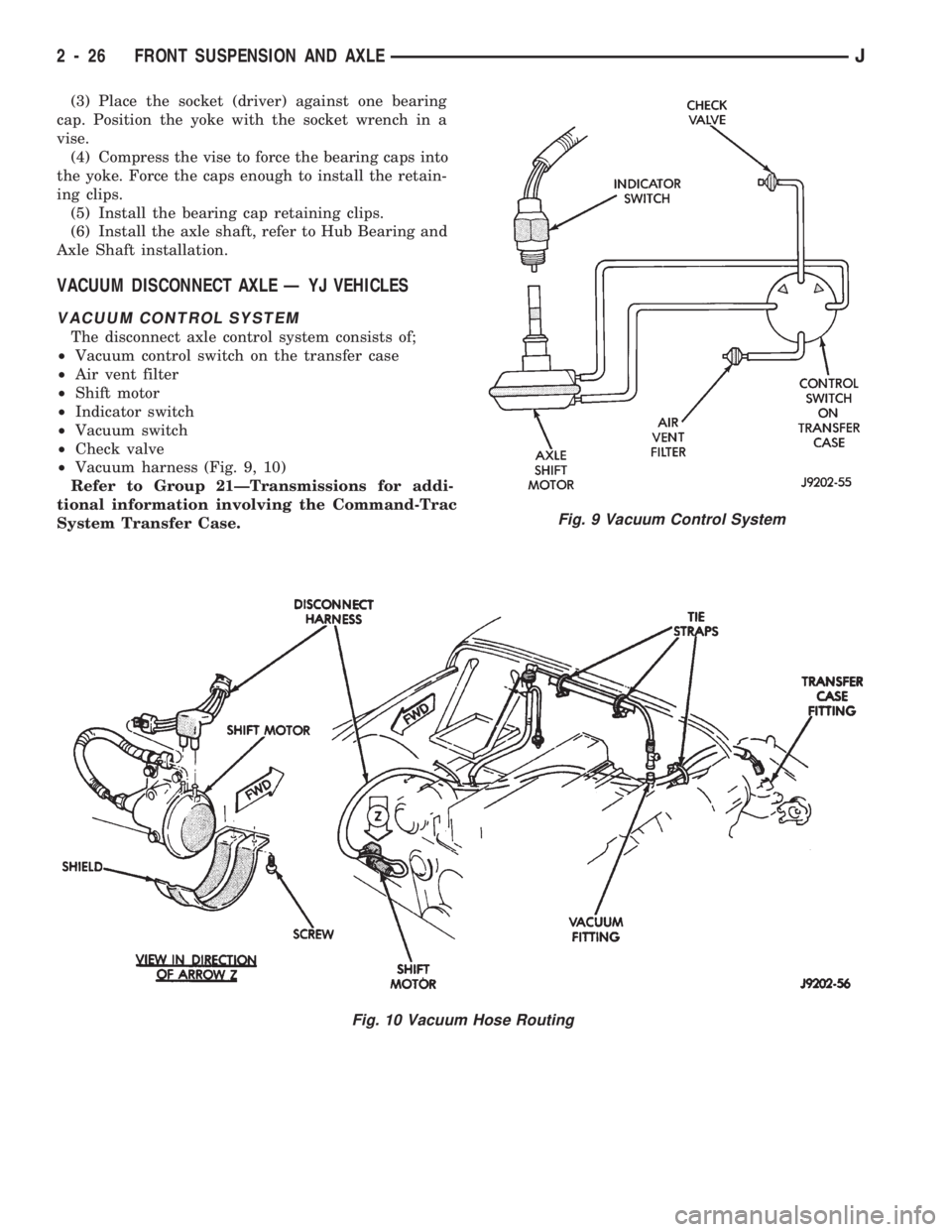
VACUUM DISCONNECT AXLE Ð YJ VEHICLES
VACUUM CONTROL SYSTEM
The disconnect axle control system consists of;
²Vacuum control switch on the transfer case
²Air vent filter
²Shift motor
²Indicator switch
²Vacuum switch
²Check valve
²Vacuum harness (Fig. 9, 10)
Refer to Group 21ÐTransmissions for addi-
tional information involving the Command-Trac
System Transfer Case.
Fig. 9 Vacuum Control System
Fig. 10 Vacuum Hose Routing
2 - 26 FRONT SUSPENSION AND AXLEJ
Page 86 of 1784

FUEL SYSTEM
CONTENTS
page page
ACCELERATOR PEDAL AND THROTTLE CABLE... 16
FUEL DELIVERY SYSTEM................. 2
FUEL TANKS........................... 12
GENERAL INFORMATION.................. 1
MULTI-PORT FUEL INJECTION (MFI)ÐCOMPO-
NENT DESCRIPTION/SYSTEM OPERATION . 17MULTI-PORT FUEL INJECTION (MFI)Ð
COMPONENT REMOVAL/INSTALLATION . . . 54
MULTI-PORT FUEL INJECTION (MFI)Ð
GENERAL DIAGNOSIS.................. 32
SPECIFICATIONS....................... 62
GENERAL INFORMATION
Throughout this group, references are made to par-
ticular vehicle models by alphabetical designation or
by the particular vehicle nameplate. A chart showing
a breakdown of the alphabetical designations is in-
cluded in the Introduction section at the beginning of
this manual.
TheFuel Systemconsists of: the fuel tank, an
electric (fuel tank mounted) fuel pump and a fuel fil-
ter. It also consists of fuel tubes/lines/hoses, vacuum
hoses, throttle body and fuel injectors.
TheFuel Delivery Systemconsists of: the electric
fuel pump, fuel filter, fuel tubes/lines/hoses, fuel rail,
fuel injectors and fuel pressure regulator.
AFuel Return Systemis used on all vehicles.
The system consists of: the fuel tubes/lines/hoses that
route fuel back to the fuel tank.
TheFuel Tank Assemblyconsists of: the fuel
tank, filler tube, fuel gauge sending unit/electric fuel
pump module, a pressure relief/rollover valve and a
pressure-vacuum filler cap.
Also to be considered part of the fuel system is the
Evaporation Control System.This is designed to
reduce the emission of fuel vapors into the atmo-
sphere. The description and function of the Evapora-
tive Control System is found in Group 25, Emission
Control Systems.
FUEL USAGE STATEMENT
Your vehicle was designed to meet all emission reg-
ulations and provide excellent fuel economy using
high quality unleaded gasoline. Only use unleaded
gasolines having a minimum posted octane of 87.
If your vehicle develops occasional light spark
knock (ping) at low engine speeds, this is not harm-
ful. However,continued heavy knock at high
speeds can cause damage and should be re-
ported to your dealer immediately.Engine dam-age as a result of heavy knock operation may not be
covered by the new vehicle warranty.
In addition to using unleaded gasoline with the
proper octane rating,those that contain deter-
gents, corrosion and stability additives are rec-
ommended.Using gasolines that have these
additives will help improve fuel economy, reduce
emissions and maintain vehicle performance. Gener-
ally, premium unleaded gasolines contain more addi-
tive than regular unleaded gasolines.
Poor quality gasolinecan cause problems such
as hard starting, stalling and stumble. If you experi-
ence these problems, use another brand of gasoline
before considering service for the vehicle.
GASOLINE/OXYGENATE BLENDS
Some fuel suppliers blend unleaded gasoline with
materials that contain oxygen such as alcohol, MTBE
and ETBE. The type and amount of oxygenate used
in the blend is important. The following are generally
used in gasoline blends:
ETHANOL
Ethanol (Ethyl or Grain Alcohol) properly blended,
is used as a mixture of 10 percent ethanol and 90
percent gasoline.Gasoline with ethanol may be
used in your vehicle.
METHANOL
CAUTION: DO NOT USE GASOLINES CONTAINING
METHANOL.Use of methanol/gasoline blends may re-
sult in starting and driveability problems. In addition,
damage may be done to critical fuel system compo-
nents.
Methanol (Methyl or Wood Alcohol) is used in a va-
riety of concentrations blended with unleaded gaso-
JFUEL SYSTEM 14 - 1
Page 87 of 1784

line. You may encounter fuels containing 3 percent
or more methanol along with other alcohols called co-
solvents.
Problems that are the result of using methanol/gas-
oline blends are not the responsibility of Chrysler
Corporation. They may not be covered by the vehicle
warranty.
MTBE/ETBE
Gasoline and MTBE (Methyl Tertiary Butyl Ether)
blends are a mixture of unleaded gasoline and up to
15 percent MTBE. Gasoline and ETBE (Ethyl Ter-
tiary Butyl Ether) are blends of gasoline and up to
17 percent ETBE. Gasoline blended with MTBE or
ETBE may be used in your vehicle.CLEAN AIR GASOLINE
Many gasolines are now being blended that con-
tribute to cleaner air, especially in those areas of the
country where air pollution levels are high. These
new blends provide a cleaner burning fuel and some
are referred to asReformulated Gasoline.
In areas of the country where carbon monoxide lev-
els are high, gasolines are being treated with oxy-
genated materials such as MTBE, ETBE and
ethanol.
Chrysler Corporation supports these efforts toward
cleaner air and recommends that you use these gas-
olines as they become available.
FUEL DELIVERY SYSTEM
INDEX
page page
Fuel Filter............................... 8
Fuel Pressure Leak Down Test............... 7
Fuel Pressure Release Procedure............. 5
Fuel Pump Capacity Test................... 7
Fuel Pump Electrical Control................. 5Fuel Pump Module........................ 2
Fuel System Pressure Test.................. 5
Fuel Tubes/Lines/Hoses and Clamps........... 9
Quick-Connect Fittings..................... 9
FUEL PUMP MODULE
The fuel pump module is installed in the top of the
fuel tank. The fuel pump module contains the follow-
ing components:
²Electric fuel pump
²Fuel pump reservoir
²In-tank fuel filter
²Fuel gauge sending unit
²Fuel supply and return tube connections
The fuel pump used on all vehicles is a gear/rotor
type pump. It is driven by a permanent magnet 12
volt electric motor that is immersed in the fuel tank.
The electrical pump is integral with the fuel sender
unit. The pump/sender assembly is installed inside
the fuel tank.
The fuel pump has a check valve at the outlet end
that consists of a ball held against a seat by force ap-
plied from a spring. When the pump is operating,
fuel pressure overcomes spring pressure and forces
the ball off its seat, allowing fuel to flow. When the
pump is not operating, spring pressure forces the ball
back against the seat preventing fuel backflow
through the pump.
Fuel system pressure is maintained at approxi-
mately 214 kPa (31 psi). This is when the pump is
operating and vacuum is supplied to the fuel pres-
sure regulator. If vacuum is not supplied to the pres-
sure regulator, fuel pressure will be approximately
55-69 kPa (8-10 psi) higher. This may be due to a
broken or clogged vacuum line. When the fuel pumpis not operating, system fuel pressure of 131-269 kPa
(19-39 psi) is maintained. This is done by the fuel
pump outlet check valve and the vacuum assisted
fuel pressure regulator.
REMOVALÐXJ MODELS
The fuel pump/gauge sender unit assembly can be
removed from the fuel tank without removing the
tank from the vehicle.
WARNING: THE FUEL SYSTEM IS UNDER A CON-
STANT PRESSURE (EVEN WITH THE ENGINE OFF).
BEFORE SERVICING THE FUEL PUMP MODULE,
THE FUEL SYSTEM PRESSURE MUST BE RE-
LEASED. REFER TO THE FUEL PRESSURE RE-
LEASE PROCEDURE IN THIS GROUP.
WARNING: EXTINGUISH ALL TOBACCO SMOKING
PRODUCTS BEFORE SERVICING THE FUEL SYS-
TEM. KEEP OPEN FLAME AWAY FROM FUEL SYS-
TEM COMPONENTS.
(1) Remove fuel filler cap. Perform the Fuel Pres-
sure Release Procedure as outlined in this group.
(2) Disconnect negative battery cable.
(3) Using an approved portable gasoline siphon/
storage tank, drain fuel tank until fuel level is below
one quarter (1/4) full.
(4) Raise and support vehicle.
14 - 2 FUEL SYSTEMJ