1994 JEEP CHEROKEE check engine
[x] Cancel search: check enginePage 916 of 1784
INSPECTIONÐCONNECTING ROD
CONNECTING ROD BEARINGS
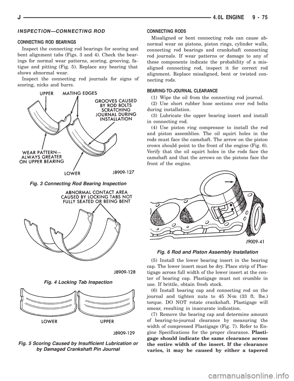
Inspect the connecting rod bearings for scoring and
bent alignment tabs (Figs. 3 and 4). Check the bear-
ings for normal wear patterns, scoring, grooving, fa-
tigue and pitting (Fig. 5). Replace any bearing that
shows abnormal wear.
Inspect the connecting rod journals for signs of
scoring, nicks and burrs.CONNECTING RODS
Misaligned or bent connecting rods can cause ab-
normal wear on pistons, piston rings, cylinder walls,
connecting rod bearings and crankshaft connecting
rod journals. If wear patterns or damage to any of
these components indicate the probability of a mis-
aligned connecting rod, inspect it for correct rod
alignment. Replace misaligned, bent or twisted con-
necting rods.
BEARING-TO-JOURNAL CLEARANCE
(1) Wipe the oil from the connecting rod journal.
(2) Use short rubber hose sections over rod bolts
during installation.
(3) Lubricate the upper bearing insert and install
in connecting rod.
(4) Use piston ring compressor to install the rod
and piston assemblies. The oil squirt holes in the
rods must face the camshaft. The arrow on the piston
crown should point to the front of the engine (Fig. 6).
Verify that the oil squirt holes in the rods face the
camshaft and that the arrows on the pistons face the
front of the engine.
(5) Install the lower bearing insert in the bearing
cap. The lower insert must be dry. Place strip of Plas-
tigage across full width of the lower insert at the cen-
ter of bearing cap. Plastigage must not crumble in
use. If brittle, obtain fresh stock.
(6) Install bearing cap and connecting rod on the
journal and tighten nuts to 45 Nzm (33 ft. lbs.)
torque. DO NOT rotate crankshaft. Plastigage will
smear, resulting in inaccurate indication.
(7) Remove the bearing cap and determine amount
of bearing-to-journal clearance by measuring the
width of compressed Plastigage (Fig. 7). Refer to En-
gine Specifications for the proper clearance.Plasti-
gage should indicate the same clearance across
the entire width of the insert. If the clearance
varies, it may be caused by either a tapered
Fig. 3 Connecting Rod Bearing Inspection
Fig. 4 Locking Tab Inspection
Fig. 5 Scoring Caused by Insufficient Lubrication or
by Damaged Crankshaft Pin Journal
Fig. 6 Rod and Piston Assembly Installation
J4.0L ENGINE 9 - 75
Page 922 of 1784
the insert approximately 25 mm (1 inch), it can be
removed by applying pressure under the tab.
(8) Using the same procedure described above, re-
move the remaining bearing inserts one at a time for
inspection.
INSPECTION
Wipe the inserts clean and inspect for abnormal
wear patterns and for metal or other foreign material
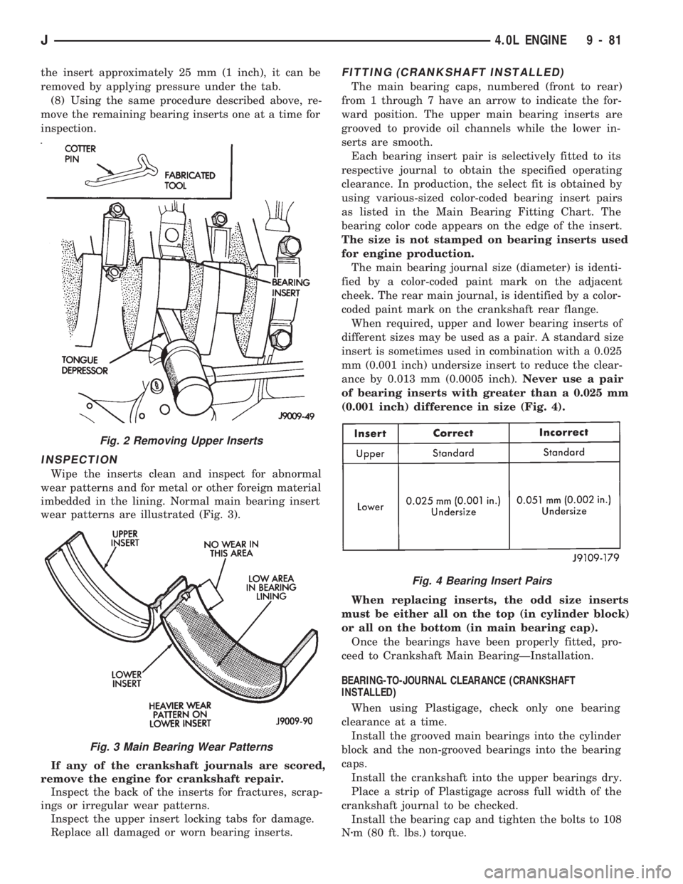
imbedded in the lining. Normal main bearing insert
wear patterns are illustrated (Fig. 3).
If any of the crankshaft journals are scored,
remove the engine for crankshaft repair.
Inspect the back of the inserts for fractures, scrap-
ings or irregular wear patterns.
Inspect the upper insert locking tabs for damage.
Replace all damaged or worn bearing inserts.
FITTING (CRANKSHAFT INSTALLED)
The main bearing caps, numbered (front to rear)
from 1 through 7 have an arrow to indicate the for-
ward position. The upper main bearing inserts are
grooved to provide oil channels while the lower in-
serts are smooth.
Each bearing insert pair is selectively fitted to its
respective journal to obtain the specified operating
clearance. In production, the select fit is obtained by
using various-sized color-coded bearing insert pairs
as listed in the Main Bearing Fitting Chart. The
bearing color code appears on the edge of the insert.
The size is not stamped on bearing inserts used
for engine production.
The main bearing journal size (diameter) is identi-
fied by a color-coded paint mark on the adjacent
cheek. The rear main journal, is identified by a color-
coded paint mark on the crankshaft rear flange.
When required, upper and lower bearing inserts of
different sizes may be used as a pair. A standard size
insert is sometimes used in combination with a 0.025
mm (0.001 inch) undersize insert to reduce the clear-
ance by 0.013 mm (0.0005 inch).Never use a pair
of bearing inserts with greater than a 0.025 mm
(0.001 inch) difference in size (Fig. 4).
When replacing inserts, the odd size inserts
must be either all on the top (in cylinder block)
or all on the bottom (in main bearing cap).
Once the bearings have been properly fitted, pro-
ceed to Crankshaft Main BearingÐInstallation.
BEARING-TO-JOURNAL CLEARANCE (CRANKSHAFT
INSTALLED)
When using Plastigage, check only one bearing
clearance at a time.
Install the grooved main bearings into the cylinder
block and the non-grooved bearings into the bearing
caps.
Install the crankshaft into the upper bearings dry.
Place a strip of Plastigage across full width of the
crankshaft journal to be checked.
Install the bearing cap and tighten the bolts to 108
Nzm (80 ft. lbs.) torque.
Fig. 2 Removing Upper Inserts
Fig. 3 Main Bearing Wear Patterns
Fig. 4 Bearing Insert Pairs
J4.0L ENGINE 9 - 81
Page 925 of 1784

(8) Check crankshaft end play. Crankshaft end
play is controlled by the thrust bearing which is
flange and installed at the No.2 main bearing posi-
tion.
(a) Attach a magnetic base dial indicator to the
cylinder block at either the front or rear of the en-
gine.
(b) Position the dial indicator rod so that it is
parallel to the center line of the crankshaft.
(c) Pry the crankshaft forward, position the dial
indicator to zero.
(d) Pry the crankshaft forward and backward.
Note the dial indicator readings. End play is the
difference between the high and low measurements
(Fig. 6). Correct end play is 0.038-0.165 mm
(0.0015-0.0065 inch). The desired specifications are
0.051-0.064 mm (0.002-0.0025 inch).
(e) If end play is not within specification, inspect
crankshaft thrust faces for wear. If no wear is ap-
parent, replace the thrust bearing and measure end
play. If end play is still not within specification, re-
place the crankshaft.
If the crankshaft was removed, install the crank-
shaft into the cylinder block (refer to Cylinder Block -
Assemble).
(9) Install the oil pan.
(10) Install the drain plug. Tighten the plug to 34
Nzm (25 ft. lbs.) torque.
(11) Lower the vehicle.
(12) Install the spark plugs. Tighten the plugs to
37 Nzm (27 ft. lbs.) torque.
(13) Fill the oil pan with engine oil to the full
mark on the dipstick level.
(14) Connect negative cable to battery.
REAR MAIN OIL SEALS
The crankshaft rear main bearing oil seal consists
of two half pieces of viton with a single lip that ef-fectively seals the rear of the crankshaft. Replace the
upper and lower seal halves as a unit to ensure leak-
free operation.
REMOVAL
(1) Remove the engine flywheel or converter drive
plate.
(2) Remove the oil pan.
(3) Remove the rear main bearing cap (No.7).
(4) Push the upper seal out of the groove. Ensure
that the crankshaft and seal groove are not damaged.
(5) Remove the lower half of the seal from the
bearing cap.
INSTALLATION
(1) Wipe the seal surface area of the crankshaft
until it is clean.
(2) Apply a thin coat of engine oil.
(3) Coat the lip of the seal with engine oil.
(4) Carefully position the upper seal into the
groove in the cylinder block. The lip of the seal faces
toward the front of the engine.
(5) Place the lower half of the seal into bearing cap
No.7 (Fig. 7).
(6) Coat the outer curved surface of the lower seal
with soap and the lip of the seal with engine oil (Fig.
7).
(7) Position the lower seal into the bearing cap re-
cess and seat it firmly. Be sure the seal is flush with
the cylinder block pan rail.
(8) Apply Loctite 515, or equivalent on the rear
bearing cap (Fig. 8). The bead should be 3 mm (0.125
in) thick. DO NOT apply Loctite 515, or equivalent
to the lip of the seal.
Fig. 7 Rear Main Bearing Oil Seal
Fig. 6 Crankshaft End Play Measurement
9 - 84 4.0L ENGINEJ
Page 938 of 1784
(2) Install the exhaust tailpipe into the muffler
outlet. Ensure that the locator on the exhaust
tailpipe aligns with the notch on the muffler, if so
equipped. Install the clamp and tighten the nuts fin-
ger tight.
(3) Install the front exhaust tailpipe supports and
the rear exhaust tailpipe hanger. Ensure that the ex-
haust tailpipe has sufficient clearance from the floor
pan and shields.
(4) Tighten the nuts on the muffler-to-catalytic
converter and the muffler-to-exhaust tailpipe clamps
to 61 Nzm (45 ft. lbs.) torque.
(5) Lower the vehicle.
(6) Start the engine and inspect for exhaust leaks
and contact with the body panels and shields.
ENGINE EXHAUST MANIFOLDÐ2.5L ENGINE
REMOVAL
(1) Disconnect the battery negative cable.
(2) Remove all components attached to the intake
manifold.
(3) Raise the vehicle.
(4) Disconnect the exhaust pipe from the engine
exhaust manifold.
(5) Lower the vehicle.
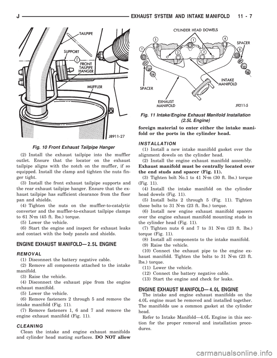
(6) Remove fasteners 2 through 5 and remove the
intake manifold (Fig. 11).
(7) Remove fasteners 1, 6 and 7 and remove the
engine exhaust manifold (Fig. 11).
CLEANING
Clean the intake and engine exhaust manifolds
and cylinder head mating surfaces.DO NOT allowforeign material to enter either the intake mani-
fold or the ports in the cylinder head.
INSTALLATION
(1) Install a new intake manifold gasket over the
alignment dowels on the cylinder head.
(2) Install the engine exhaust manifold assembly.
Exhaust manifold must be centrally located over
the end studs and spacer (Fig. 11).
(3) Tighten bolt No.1 to 41 Nzm (30 ft. lbs.) torque
(Fig. 11).
(4) Install the intake manifold on the cylinder
head dowels (Fig. 11).
(5) Install bolts 2 through 5 (Fig. 11). Tighten
these bolts to 31 Nzm (23 ft. lbs.) torque.
(6) Install new engine exhaust manifold spacers
over the engine exhaust manifold mounting studs in
the cylinder head (Fig. 11).
(7) Tighten nuts 6 and 7 to 31 Nzm (23 ft. lbs.)
torque (Fig. 11).
(8) Install all components to the intake manifold.
(9) Raise the vehicle.
(10) Connect the exhaust pipe to the engine ex-
haust manifold. Tighten the bolts to 31 Nzm (23 ft.
lbs.) torque.
(11) Lower the vehicle.
(12) Connect the battery negative cable.
(13) Start the engine and check for leaks.
ENGINE EXHAUST MANIFOLDÐ4.0L ENGINE
The intake and engine exhaust manifolds on the
4.0L engine must be removed and installed together.
The manifolds use a common gasket at the cylinder
head.
Refer to Intake ManifoldÐ4.0L Engine in this sec-
tion for the proper removal and installation proce-
dures.
Fig. 10 Front Exhaust Tailpipe Hanger
Fig. 11 Intake/Engine Exhaust Manifold Installation
(2.5L Engine)
JEXHAUST SYSTEM AND INTAKE MANIFOLD 11 - 7
Page 940 of 1784
CAUTION: Ensure that the accessory drive belt is
routed correctly. Failure to do so can cause the wa-
ter pump to turn in the opposite direction resulting
in engine overheating. Refer to Group 7, Cooling
System for the proper procedure.
(10) Tension the accessory drive belt. Refer to
Group 7, Cooling System for the proper procedure.
(11) Connect the air inlet hose to the throttle body
and the air cleaner.
(12) Connect the battery negative cable.
(13) Start the engine and check for leaks.
INTAKE MANIFOLDÐ4.0L ENGINE
The intake and engine exhaust manifolds on the
4.0L engine must be removed and installed together.
The two manifolds use a common gasket at the cyl-
inder head.
REMOVAL
(1) Disconnect the battery negative cable.
(2) Remove air cleaner inlet hose from throttle
plate assembly.
(3) Remove the air cleaner assembly.
(4) Remove the throttle cable, cruise control cable (if
equipped) and the transmission line pressure cable.
(5) Disconnect all electrical connectors on the in-
take manifold.
(6) Disconnect and remove the fuel supply and re-
turn lines from the fuel rail assembly (refer to Group
14, Fuel System).
(7) Loosen the accessory drive belt (refer to Group
7, Cooling System). Loosen the tensioner.
(8) Remove the power steering pump and bracket
from the intake manifold and set aside.
(9) Remove the fuel rail and injectors (refer to
Group 14, Fuel System).
(10) Raise the vehicle.
(11) Disconnect the exhaust pipe from the engine
exhaust manifold. Discard the seal.
(12) Lower the vehicle.
(13) Remove the intake manifold and engine ex-
haust manifold.
CLEANING
Clean the mating surfaces of the cylinder head and
the manifold if the original manifold is to be installed.
If the manifold is being replaced, ensure all the fit-
ting, etc. are transferred to the replacement manifold.
INSTALLATION
(1) Install a new exhaust/intake manifold gasket
over the alignment dowels on the cylinder head.
(2) Position the engine exhaust manifold to the
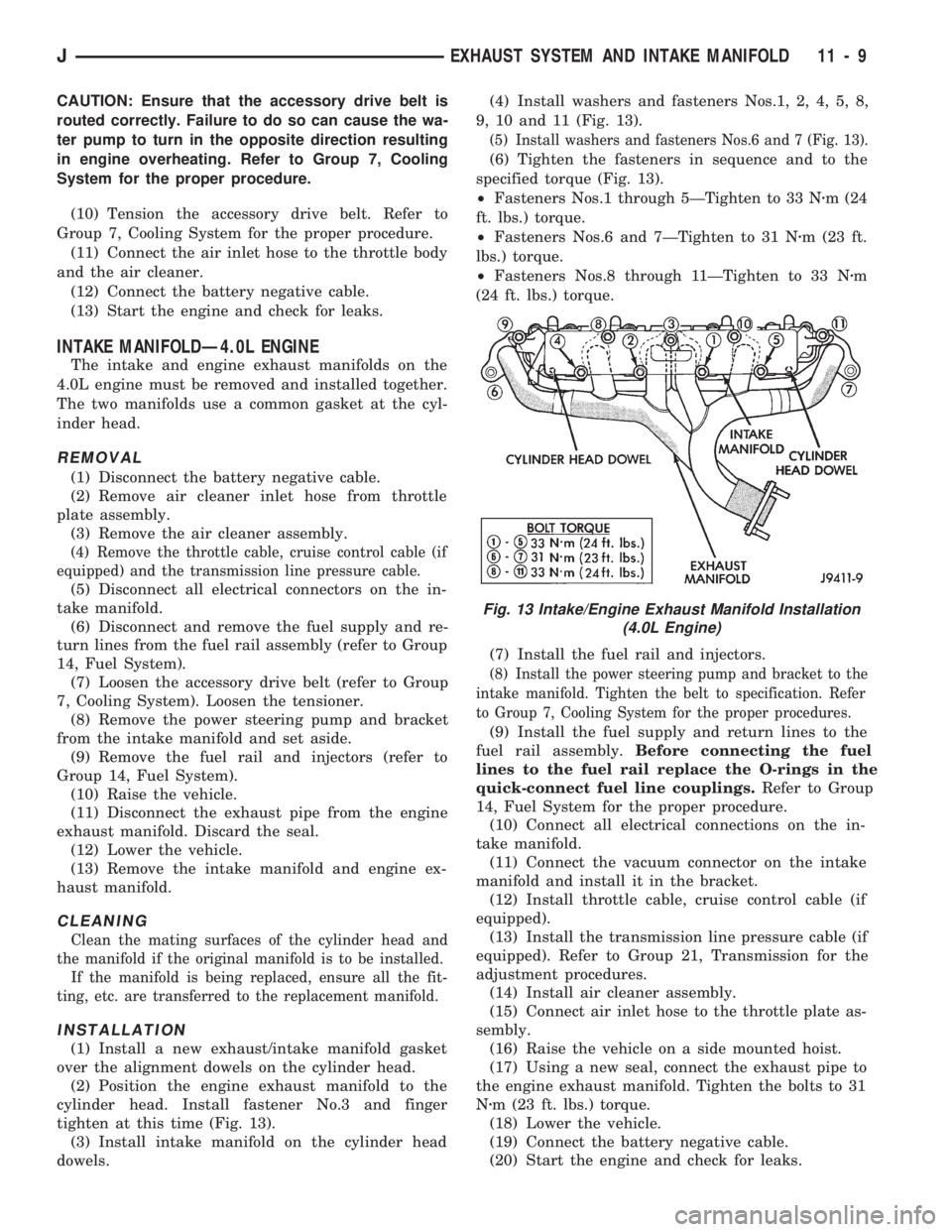
cylinder head. Install fastener No.3 and finger
tighten at this time (Fig. 13).
(3) Install intake manifold on the cylinder head
dowels.(4) Install washers and fasteners Nos.1, 2, 4, 5, 8,
9, 10 and 11 (Fig. 13).
(5) Install washers and fasteners Nos.6 and 7 (Fig. 13).
(6) Tighten the fasteners in sequence and to the
specified torque (Fig. 13).
²Fasteners Nos.1 through 5ÐTighten to 33 Nzm (24
ft. lbs.) torque.
²Fasteners Nos.6 and 7ÐTighten to 31 Nzm (23 ft.
lbs.) torque.
²Fasteners Nos.8 through 11ÐTighten to 33 Nzm
(24 ft. lbs.) torque.
(7) Install the fuel rail and injectors.
(8) Install the power steering pump and bracket to the
intake manifold. Tighten the belt to specification. Refer
to Group 7, Cooling System for the proper procedures.
(9) Install the fuel supply and return lines to the
fuel rail assembly.Before connecting the fuel
lines to the fuel rail replace the O-rings in the
quick-connect fuel line couplings.Refer to Group
14, Fuel System for the proper procedure.
(10) Connect all electrical connections on the in-
take manifold.
(11) Connect the vacuum connector on the intake
manifold and install it in the bracket.
(12) Install throttle cable, cruise control cable (if
equipped).
(13) Install the transmission line pressure cable (if
equipped). Refer to Group 21, Transmission for the
adjustment procedures.
(14) Install air cleaner assembly.
(15) Connect air inlet hose to the throttle plate as-
sembly.
(16) Raise the vehicle on a side mounted hoist.
(17) Using a new seal, connect the exhaust pipe to
the engine exhaust manifold. Tighten the bolts to 31
Nzm (23 ft. lbs.) torque.
(18) Lower the vehicle.
(19) Connect the battery negative cable.
(20) Start the engine and check for leaks.
Fig. 13 Intake/Engine Exhaust Manifold Installation
(4.0L Engine)
JEXHAUST SYSTEM AND INTAKE MANIFOLD 11 - 9
Page 963 of 1784
line. You may encounter fuels containing 3 percent
or more methanol along with other alcohols called co-
solvents.
Problems that are the result of using methanol/gas-
oline blends are not the responsibility of Chrysler
Corporation. They may not be covered by the vehicle
warranty.
MTBE/ETBE
Gasoline and MTBE (Methyl Tertiary Butyl Ether)
blends are a mixture of unleaded gasoline and up to
15 percent MTBE. Gasoline and ETBE (Ethyl Ter-
tiary Butyl Ether) are blends of gasoline and up to
17 percent ETBE. Gasoline blended with MTBE or
ETBE may be used in your vehicle.CLEAN AIR GASOLINE
Many gasolines are now being blended that con-
tribute to cleaner air, especially in those areas of the
country where air pollution levels are high. These
new blends provide a cleaner burning fuel and some
are referred to asReformulated Gasoline.
In areas of the country where carbon monoxide lev-
els are high, gasolines are being treated with oxy-
genated materials such as MTBE, ETBE and
ethanol.
Chrysler Corporation supports these efforts toward
cleaner air and recommends that you use these gas-
olines as they become available.
FUEL DELIVERY SYSTEM
INDEX
page page
Fuel Filter............................... 8
Fuel Pressure Leak Down Test............... 7
Fuel Pressure Release Procedure............. 5
Fuel Pump Capacity Test................... 7
Fuel Pump Electrical Control................. 5Fuel Pump Module........................ 2
Fuel System Pressure Test.................. 5
Fuel Tubes/Lines/Hoses and Clamps........... 9
Quick-Connect Fittings..................... 9
FUEL PUMP MODULE
The fuel pump module is installed in the top of the
fuel tank. The fuel pump module contains the follow-
ing components:
²Electric fuel pump
²Fuel pump reservoir
²In-tank fuel filter
²Fuel gauge sending unit
²Fuel supply and return tube connections
The fuel pump used on all vehicles is a gear/rotor
type pump. It is driven by a permanent magnet 12
volt electric motor that is immersed in the fuel tank.
The electrical pump is integral with the fuel sender
unit. The pump/sender assembly is installed inside
the fuel tank.
The fuel pump has a check valve at the outlet end
that consists of a ball held against a seat by force ap-
plied from a spring. When the pump is operating,
fuel pressure overcomes spring pressure and forces
the ball off its seat, allowing fuel to flow. When the
pump is not operating, spring pressure forces the ball
back against the seat preventing fuel backflow
through the pump.
Fuel system pressure is maintained at approxi-
mately 214 kPa (31 psi). This is when the pump is
operating and vacuum is supplied to the fuel pres-
sure regulator. If vacuum is not supplied to the pres-
sure regulator, fuel pressure will be approximately
55-69 kPa (8-10 psi) higher. This may be due to a
broken or clogged vacuum line. When the fuel pumpis not operating, system fuel pressure of 131-269 kPa
(19-39 psi) is maintained. This is done by the fuel
pump outlet check valve and the vacuum assisted
fuel pressure regulator.
REMOVALÐXJ MODELS
The fuel pump/gauge sender unit assembly can be
removed from the fuel tank without removing the
tank from the vehicle.
WARNING: THE FUEL SYSTEM IS UNDER A CON-
STANT PRESSURE (EVEN WITH THE ENGINE OFF).
BEFORE SERVICING THE FUEL PUMP MODULE,
THE FUEL SYSTEM PRESSURE MUST BE RE-
LEASED. REFER TO THE FUEL PRESSURE RE-
LEASE PROCEDURE IN THIS GROUP.
WARNING: EXTINGUISH ALL TOBACCO SMOKING
PRODUCTS BEFORE SERVICING THE FUEL SYS-
TEM. KEEP OPEN FLAME AWAY FROM FUEL SYS-
TEM COMPONENTS.
(1) Remove fuel filler cap. Perform the Fuel Pres-
sure Release Procedure as outlined in this group.
(2) Disconnect negative battery cable.
(3) Using an approved portable gasoline siphon/
storage tank, drain fuel tank until fuel level is below
one quarter (1/4) full.
(4) Raise and support vehicle.
14 - 2 FUEL SYSTEMJ
Page 966 of 1784
(3) Install new fuel pump outlet hose. Secure with
new clamps.
(4) Connect wire terminals to motor.
(5) Install new fuel pump inlet filter.
INSTALLATIONÐYJ MODELS
(1) Install a new fuel pump inlet filter.
(2) Install fuel pump module assembly with a new
gasket between the assembly and tank. Tighten
mounting screws to 2 Nzm (18 in. lbs.) torque.
(3) Install fuel tank. Refer to Fuel Tank Installa-
tionÐYJ Models.
(4) Fill fuel tank. Install fuel tank cap.
(5) Install negative battery cable.
(6) Start vehicle and check for leaks.
FUEL PUMP ELECTRICAL CONTROL
For an electrical operational description of the fuel
pump, refer to the MFI SystemÐComponent Descrip-
tion/System Operation section of this group. See Au-
tomatic Shut Down (ASD) RelayÐPCM Output.
For the 1994 model year, the ballast resistor and
ballast resistor bypass relay are no longer used to
control the fuel pump circuit.
FUEL PRESSURE RELEASE PROCEDURE
WARNING: THE FUEL SYSTEM IS UNDER CON-
STANT FUEL PRESSURE (EVEN WITH THE ENGINE
OFF) OF APPROXIMATELY 131-269 KPA (19-39
PSI). THIS PRESSURE MUST BE RELEASED BE-
FORE SERVICING ANY FUEL SUPPLY OR FUEL RE-
TURN SYSTEM COMPONENT.
(1) Disconnect negative battery cable.
(2) Remove fuel tank filler neck cap to release fuel
tank pressure.
WARNING: DO NOT ALLOW FUEL TO SPILL ONTO
THE ENGINE INTAKE OR EXHAUST MANIFOLDS.
PLACE SHOP TOWELS UNDER AND AROUND THE
PRESSURE PORT TO ABSORB FUEL WHEN THE
PRESSURE IS RELEASED FROM THE FUEL RAIL.
WARNING: WEAR PROPER EYE PROTECTION
WHEN RELEASING FUEL SYSTEM PRESSURE.
(3) Remove protective cap from pressure test port
on the fuel rail (Fig. 7).
(4) Obtain the fuel pressure gauge/hose assembly
from fuel pressure gauge tool set 5069. Remove the
gauge from the hose.
(5) Place one end of hose (gauge end) into an ap-
proved gasoline container.
(6) Place a shop towel under the test port.
(7) To release fuel pressure, screw the other end of
hose onto the fuel pressure test port.(8) After fuel pressure has been released, remove
the hose from the test port.
(9) Install protective cap to fuel test port.
FUEL SYSTEM PRESSURE TEST
The fuel system is equipped with a vacuum as-
sisted fuel pressure regulator (Fig. 8). With engine at
idle speed, system fuel pressure should be approxi-
mately 214 kPa (31 psi) with the vacuum line con-
nected to the regulator. With the vacuum line
disconnected from the regulator, fuel pressure should
be approximately 269 kPa (39 psi). This is 55-69 kPa
(8-10 psi) higher.
(1) Remove the protective cap at the fuel rail (Fig.
7). Connect the 0-414 kPa (0-60 psi) fuel pressure
gauge (from Gauge Set 5069) to test port pressure fit-
ting on fuel rail (Fig. 9).
(2) Note pressure gauge reading. Fuel pressure
should be approximately 214 kPa (31 psi) at idle.
Fig. 7 Pressure Test PortÐTypical
Fig. 8 Fuel Pressure RegulatorÐTypical
JFUEL SYSTEM 14 - 5
Page 968 of 1784
FUEL PUMP CAPACITY TEST
Before performing this test, verify fuel pump pres-
sure by performing the previous tests.
(1) Release the fuel system pressure from fuel sys-
tem. Refer to the previous Fuel Pressure Release
Procedure in this group.
(2) Disconnect the fuel supply line at fuel rail near
pressure regulator. For procedures, refer to Fuel
Tubes/Lines/Hoses and Clamps. Also refer to Quick-
Connect Fittings. These can be found in the Fuel De-
livery System section of this group.
(3) Connect Fuel Line Pressure Test Adapter Tool
number 6631 (3/8 in.) into the disconnected fuel sup-
ply line. Insert the other end of tool 6631 into an ap-
proved gasoline container.
(4) To activate the fuel pump and pressurize the
system, obtain the DRB scan tool. Refer to the appro-
priate Powertrain Diagnostic Procedures service
manual for DRB operation.
A good fuel pump will deliver at least 1 liter of fuel
per minute.
FUEL PRESSURE LEAK DOWN TEST
ENGINE OFF
Abnormally long periods of cranking to restart a
hot engine that has been shut down for a short pe-
riod of time may be caused by:
²Fuel pressure bleeding past the fuel pressure reg-
ulator.
²Fuel pressure bleeding past the check valve in the
outlet end of the fuel tank mounted fuel pump.
(1) Remove protective cap at fuel rail test port
(Fig. 11). With the engine off, connect an accurate
0-689 kPa (0-100 psi) fuel gauge to the pressure test
port fitting on the fuel rail. The fitting on the pres-
sure tester must be in good condition and free of any
leaks before performing this test.(2) Start the vehicle and let engine idle. Check
fuel pressure reading on gauge. Fuel pressure should
be within specifications. Refer to the previous Fuel
System Pressure Tests.
(3) Shut engine off. Observe and record fuel pres-
sure reading on gauge. Leave fuel pressure gauge
connected. Allow engine to set for 30 minutes and
then compare the fuel pressure reading on the gauge
with the reading taken when engine was shut down.
A pressure drop of up to 138 kPa (20 psi) within 30
minutes is within specifications.
(4) If the fuel pressure drop is within specifica-
tions, the fuel pump outlet check valve and fuel pres-
sure regulator are both operating normally.
(5) If fuel pressure drop is greater than 138 kPa
(20 psi), it must be determined if this drop is being
caused by (in-tank mounted) fuel pump outlet check
valve or fuel pressure regulator. Proceed to next step.
(6) Release the fuel system pressure from fuel sys-
tem. Refer to the previous Fuel Pressure Release
Procedure in this group.
(7) Disconnect both fuel lines at fuel rail near fuel
pressure regulator. For procedures, refer to Fuel
Tubes/Lines/Hoses and Clamps. Also refer to Quick-
Connect Fittings. These can be found in the Fuel De-
livery System section of this group.
(8) Connect Fuel Line Pressure Test Adapter Tool
number 6631 (3/8 in.) between the disconnected fuel
supply line and fuel rail (Fig. 12).
(9) Connect Fuel Line Pressure Test Adapter Tool
number 6539 (5/16 in.) between the disconnected fuel
return line and fuel rail (Fig. 12).
(10) Start engine. Observe and record fuel system
pressure.
(11) Shut engine off.
(12) Clamp off the rubber hose portion of adapter
tool number 6539 connected to the fuel return line.
Allow engine to set for 30 minutes. If pressure has
dropped more than 138 kPa (20 psi) in 30 minutes,
Fig. 11 Fuel Pressure Test PortÐTypical
Fig. 12 Adapter ToolsÐTypical Connections
JFUEL SYSTEM 14 - 7