1994 JEEP CHEROKEE check engine
[x] Cancel search: check enginePage 384 of 1784
ANTENNA TESTS
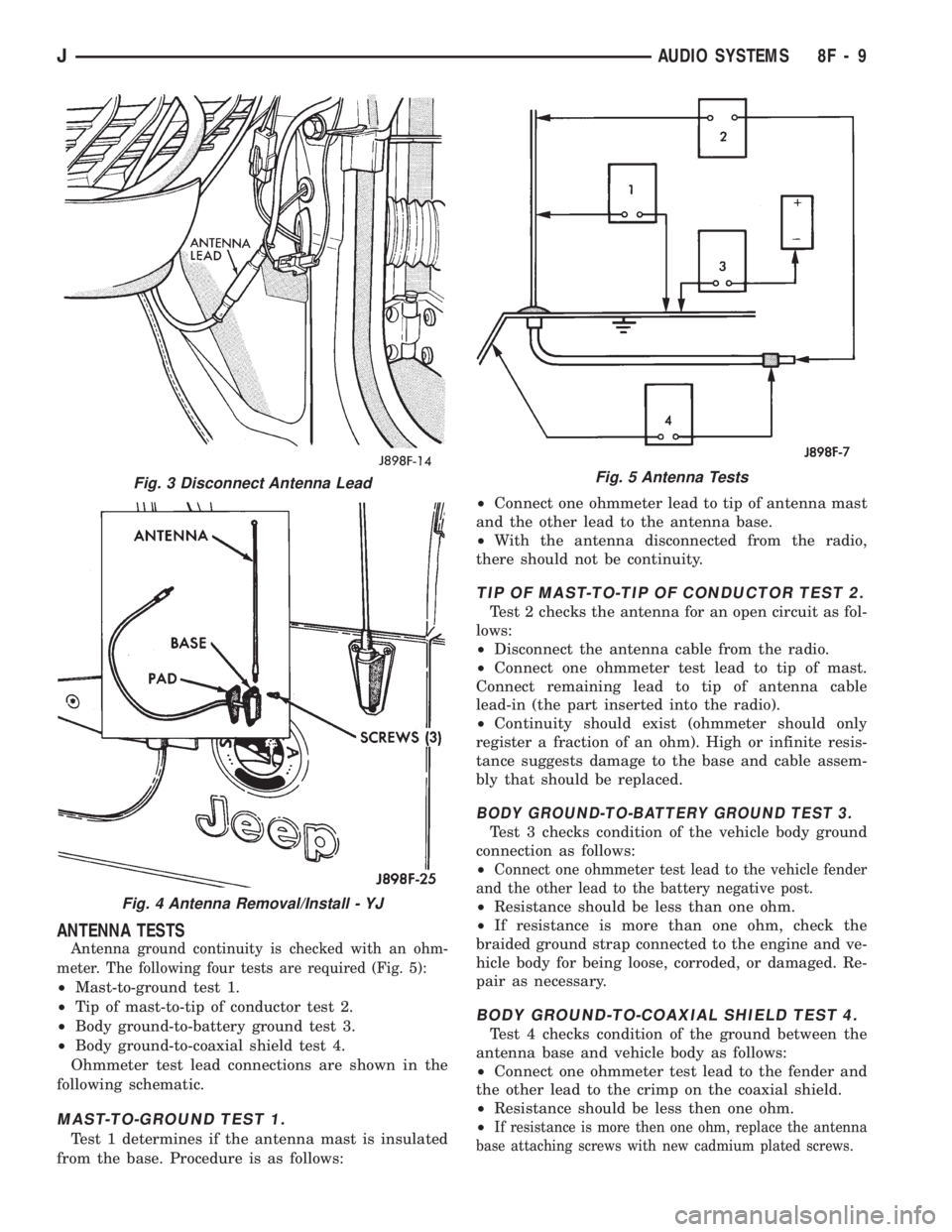
Antenna ground continuity is checked with an ohm-
meter. The following four tests are required (Fig. 5):
²Mast-to-ground test 1.
²Tip of mast-to-tip of conductor test 2.
²Body ground-to-battery ground test 3.
²Body ground-to-coaxial shield test 4.
Ohmmeter test lead connections are shown in the
following schematic.
MAST-TO-GROUND TEST 1.
Test 1 determines if the antenna mast is insulated
from the base. Procedure is as follows:²Connect one ohmmeter lead to tip of antenna mast
and the other lead to the antenna base.
²With the antenna disconnected from the radio,
there should not be continuity.
TIP OF MAST-TO-TIP OF CONDUCTOR TEST 2.
Test 2 checks the antenna for an open circuit as fol-
lows:
²Disconnect the antenna cable from the radio.
²Connect one ohmmeter test lead to tip of mast.
Connect remaining lead to tip of antenna cable
lead-in (the part inserted into the radio).
²Continuity should exist (ohmmeter should only
register a fraction of an ohm). High or infinite resis-
tance suggests damage to the base and cable assem-
bly that should be replaced.
BODY GROUND-TO-BATTERY GROUND TEST 3.
Test 3 checks condition of the vehicle body ground
connection as follows:
²
Connect one ohmmeter test lead to the vehicle fender
and the other lead to the battery negative post.
²Resistance should be less than one ohm.
²If resistance is more than one ohm, check the
braided ground strap connected to the engine and ve-
hicle body for being loose, corroded, or damaged. Re-
pair as necessary.
BODY GROUND-TO-COAXIAL SHIELD TEST 4.
Test 4 checks condition of the ground between the
antenna base and vehicle body as follows:
²Connect one ohmmeter test lead to the fender and
the other lead to the crimp on the coaxial shield.
²Resistance should be less then one ohm.
²
If resistance is more then one ohm, replace the antenna
base attaching screws with new cadmium plated screws.
Fig. 3 Disconnect Antenna Lead
Fig. 4 Antenna Removal/Install - YJ
Fig. 5 Antenna Tests
JAUDIO SYSTEMS 8F - 9
Page 394 of 1784
TEST PROCEDURES
INDEX
page page
Checking for Diagnostic Trouble Code......... 5
Electrical Tests at Powertrain Control Module.... 6
Electrical Tests at Servo.................... 5
Inoperative System........................ 5
Operational Check (Road Test)............... 7
Road Test............................... 5Speed Control Switch (Turn Signal Lever) Test . . . 7
Stop Lamp Speed Control Switch Test......... 7
Vacuum Supply Test....................... 7
Vehicle Speed Control System Electrical Tests . . . 5
Vehicle Speed Sensor Test.................. 5
ROAD TEST
Refer to Operational Check (Road Test) section to
verify reports of speed control system malfunction.
INOPERATIVE SYSTEM
Road test vehicle to verify reports of speed control
system malfunction. An inspection should be made
for loose electrical and vacuum connections at the
servo.
Check for correct installation of the vacuum check
valve in the hose from servo to vacuum source. The
word VAC on the valve must point toward the vac-
uum source.
Corrosion should be removed from electrical termi-
nals and a light coating of Mopar MultiPurpose
Grease, or equivalent, applied.
Inspection also should be made to verify that both
ends of the speed control cable are securely attached.
CHECKING FOR DIAGNOSTIC TROUBLE CODE
(1) When trying to verify a speed control system
electronic malfunction use a DRB scan tool to find
the cause (refer to Powertrain Diagnostic Procedures
manual).
If DRB is not available, the Diagnostic Trouble
Code (DTC) may be determined with the following
method:
(a) With key inserted in ignition switch, cycle
switch to ON position 3 times. On third cycle, leave
switch in ON position.
(b) After switch has been cycled 3 times, observe
Malfunction Indicator Lamp (CHECK ENGINE)
on instrument cluster. If a DTC is present, the code
will be displayed in a series of flashes representing
digits. Three flashes in rapid succession, a slight
pause, then 4 flashes in rapid succession would in-
dicate DTC 34.
(2) If a DTC 34 is observed, perform tests in the
sections Electrical Tests at Servo and Electrical Tests
at Powertrain Control Module.
If a DTC 15 is observed, perform test for a faulty
vehicle speed sensor.
(3) Correct any problems found when performing
these tests and recheck for DTC if changes were
made.
VEHICLE SPEED SENSOR TEST
For testing of the vehicle speed sensor and related
components, refer to Powertrain Diagnostic Proce-
dures manual.
VEHICLE SPEED CONTROL SYSTEM ELECTRICAL
TESTS
Vehicle speed control systems may be tested using
two different methods. One involves use of a DRB
scan tool. If this test method is desired, refer to Pow-
ertrain Diagnostic Procedures manual.
The other test method uses a voltmeter. The volt-
meter method is described in the following tests.
If any information is needed concerning wiring, re-
fer to Section 8W - Wiring Diagrams.
CAUTION: When test probing for voltage or conti-
nuity at electrical connectors, care must be taken
not to damage connector, terminals, or seals. If
these components are damaged, intermittent or
complete system failure may occur.
ELECTRICAL TESTS AT SERVO
(1) Turn ignition switch to the ON position. With
speed control switch in the ON position, setup a volt-
meter to read battery voltage and connect negative
lead to a good chassis ground.
(2) Disconnect 4-way connector going to servo
(Figs. 2 and 3). Blue wire with red tracer of main
harness 4-way connector should read approximately
battery voltage. If not, check for loose connections,
brake switch adjustment or, repair main harness as
necessary.
(3) Connect a jumper wire between male and fe-
male terminals of blue wire with red tracer. The
other 3 male terminals from servo should show bat-
tery voltage. If not, replace servo.
(4) Using an ohmmeter, connect one lead to a good
body ground. Touch other lead to black wire terminal
in 4-way connector of main harness. Meter should
show continuity. If not, repair ground circuit as nec-
essary.
JVEHICLE SPEED CONTROL SYSTEM 8H - 5
Page 396 of 1784
perform the speed control switch test. If switch is not
at fault, then check main harness and repair as nec-
essary.
(8) Using an ohmmeter, connect one lead to a good
body ground and touch other lead to terminal in cav-
ity number 29. With brake pedal released, meter
should show continuity. When pedal is depressed,
meter should show open circuit.
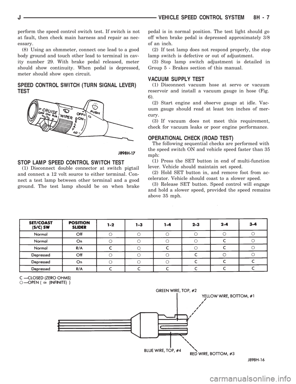
SPEED CONTROL SWITCH (TURN SIGNAL LEVER)
TEST
STOP LAMP SPEED CONTROL SWITCH TEST
(1) Disconnect double connector at switch pigtail
and connect a 12 volt source to either terminal. Con-
nect a test lamp between other terminal and a good
ground. The test lamp should be on when brakepedal is in normal position. The test light should go
off when brake pedal is depressed approximately 3/8
of an inch.
(2) If test lamp does not respond properly, the stop
lamp switch is defective or out of adjustment.
(3) Stop lamp switch adjustment is detailed in
Group 5 - Brakes section of this manual.
VACUUM SUPPLY TEST
(1) Disconnect vacuum hose at servo or vacuum
reservoir and install a vacuum gauge in hose (Fig.
6).
(2) Start engine and observe gauge at idle. Vac-
uum gauge should read at least ten inches of mer-
cury.
(3) If vacuum does not meet this requirement,
check for vacuum leaks or poor engine performance.
OPERATIONAL CHECK (ROAD TEST)
The following sequential checks are performed with
the speed switch ON and vehicle speed faster than 35
mph:
(1) Press the SET button in end of multi-function
lever. Vehicle should maintain set speed.
(2) Hold SET button in, and remove foot from ac-
celerator. Vehicle should coast to a slower speed.
(3) Release SET button. Speed control will engage
and hold a slower speed, provided the speed remains
above 35 mph.
JVEHICLE SPEED CONTROL SYSTEM 8H - 7
Page 402 of 1784

TURN SIGNALS AND HAZARD WARNING FLASHER
CONTENTS
page page
HAZARD LAMPSÐXJ.................... 1
HAZARD LAMPSÐYJ.................... 2
TURN SIGNALSÐXJ..................... 1TURN SIGNALSÐYJ..................... 2
TURN/HAZARD SWITCH REPLACEMENT - ALL
MODELS............................. 3
TURN SIGNALSÐXJ
Refer to Section 8W - Wiring Diagrams for cir-
cuit wiring diagram.
DESCRIPTION
With the turn signal lever in its up or down posi-
tion and the ignition switch in ACCESSORY or ON,
current flows through the:
²turn/hazard switch
²selected turn indicator bulb
²front and rear turn signal bulbs
²and the front side marker bulb.
With the headlamps OFF, the turn and front side
marker lamps flash in unison.With the headlamps
ON, the turn and front side marker lamps flash al-
ternately.
DIAGNOSISÐTURN SIGNAL INOPERATIVE
(1) A turn signal indicator that does not flash usu-
ally indicates a burned out turn signal bulb. Check
for and replace if defective. System should now func-
tion properly. If not, go to next step.
High generator output voltage can burn out
lamps rapidly.(2) Remove and inspect 20 amp #8 fuse. Replace if
necessary. If OK, go to next step.
(3) Remove turn flasher, light blue can, located in
upper left corner of fuse block.
(4) Turn ignition switch to ACCESSORY. Check
for battery voltage at flasher bottom cavity on fuse
block. If OK, go to next step. If not, repair open cir-
cuit in wiring between turn flasher and #8 fuse.
(5) Turn ignition switch to ACCESSORY. Move
turn signal lever up or down. Replace turn flasher
with known good flasher. The lamps should flash. If
not, replace original flasher and go to next step.
(6) Turn ignition switch to OFF. Follow procedure
for turn/hazard switch replacement to locate steering
column connector. Unplug connector.
(7) Turn ignition switch to ACCESSORY. Check
for battery voltage at connector terminal L. If OK,
replace turn/hazard switch and check that lamps
flash. If not, repair open circuit in wiring between
turn flasher and steering column connector terminal
L.
HAZARD LAMPSÐXJ
Refer to Section 8W - Wiring Diagrams for cir-
cuit wiring diagram.
DESCRIPTION
With the hazard switch ON, current flows through
the:
²hazard flasher
²the turn/hazard switch
²two front turn signal bulbs
²two rear turn signal bulbs
²two front side marker bulbs
²and two turn indicator bulbs.
All of these bulbs will flash on and off.
DIAGNOSISÐHAZARD LAMPS INOPERATIVE
(1) Inspect 20 amp #F13 fuse in Power Distribu-
tion Center (PDC). The PDC is located in the engine
compartment, passenger side. For location of fuse,check underside of PDC cover. Replace if necessary.
If OK, go to next step.
(2) Remove hazard flasher (tin can) located in fuse
block.
(3) Check for battery voltage at the terminal on
the right (3 o'clock). If OK, go to next step. If not, re-
pair open circuit in wiring between #F13 fuse and
hazard flasher right terminal.
(4) Replace hazard flasher with known good
flasher. Activate hazard warning switch. Lamps
should flash. If not, replace original flasher and go to
next step.
(5) Follow procedure for turn/hazard switch re-
placement to locate steering column connector. Un-
plug connector.
(6) Check for battery voltage at connector terminal
K. If OK, replace turn/hazard switch. If not, repair
open circuit in wiring between hazard flasher and
steering column connector terminal K.
JTURN SIGNALS AND HAZARD WARNING FLASHER 8J - 1
Page 403 of 1784

TURN SIGNALSÐYJ
Refer to Section 8W - Wiring Diagrams for cir-
cuit wiring diagram.
DESCRIPTION
With the turn signal lever in its up or down posi-
tion and the ignition switch in ACCESSORY or ON,
current flows through the:
²turn/hazard switch
²selected turn indicator bulb
²front and rear turn signal bulbs
²front side marker bulb
With the headlamps OFF, the turn and side
marker lamps flash in unison.With the headlamps
ON, the turn and side marker lamps flash alter-
nately.
DIAGNOSINGÐTURN SIGNAL INOPERATIVE
(1) A turn signal indicator that does not flash usu-
ally indicates a burned out turn signal bulb. Check
for and replace if defective. System should now func-
tion properly. If not, go to next step.
High generator output voltage can burn out
lamps rapidly.
(2) Locate fuse block under driver's side of instru-
ment panel.(3) Remove and inspect 15 amp #4 fuse. Replace if
necessary. If OK, go to next step.
(4) Remove turn flasher, light blue can, located in
fuse block.
(5) Turn ignition switch to ACCESSORY. Check
for battery voltage at cavity on left (closest to hazard
flasher can). If OK, go to next step. If not, repair
open circuit in wiring between turn flasher and #4
fuse.
(6) Turn ignition switch to ACCESSORY. Move
turn signal lever up or down. Replace turn flasher
with known good flasher. The lamps should flash. If
not, replace original flasher and go to next step.
(7) Turn ignition switch to OFF. Follow procedure
for turn/hazard switch replacement to locate steering
column connector. Unplug connector.
(8) Turn ignition switch to ACCESSORY. Check
for battery voltage at connector terminal L. If OK,
replace turn/hazard switch. If not, repair open circuit
in wiring between turn flasher and steering column
connector terminal L.
HAZARD LAMPSÐYJ
Refer to Section 8W - Wiring Diagrams for cir-
cuit wiring diagram.
DESCRIPTION
With the hazard switch ON, current flows through
the:
²hazard flasher
²turn/hazard switch
²two front turn signal bulbs
²two rear turn signal bulbs
²two front side marker bulbs
²two turn indicator bulbs.
All of these bulbs will flash on and off.
DIAGNOSISÐHAZARD LAMPS INOPERATIVE
(1) Inspect 20 amp #F5 fuse in Power Distribution
Center (PDC). The PDC is located in the engine com-
partment, passenger side. For location of fuse, check
underside of PDC cover. Replace if necessary. If OK,
go to next step.(2) Remove hazard flasher (tin can) located in fuse
block.
(3) Check for battery voltage at the terminal on
the left. If OK, go to next step. If not, repair open cir-
cuit in wiring between #F5 fuse and hazard flasher
left terminal.
(4) Replace hazard flasher with known good
flasher. Activate hazard warning switch. Lamps
should flash. If not, replace original flasher and go to
next step.
(5) Follow procedure for turn/hazard switch re-
placement to locate steering column connector. Un-
plug connector.
(6) Check for battery voltage at connector terminal
K. If OK, replace turn/hazard switch. If not, repair
open circuit in wiring between hazard flasher and
steering column connector terminal K.
8J - 2 TURN SIGNALS AND HAZARD WARNING FLASHERJ
Page 413 of 1784
(2) Install the mounting screws.
(3) Connect the wiring harness.
(4) Install the pivot pin, seal, bezel and attaching
nut (Fig. 2). Torque nut to 4 Nzm (32 in. lbs.).
(5) Connect interior washer hose.
Lubricate the bezel nipples with a small amount
of water and then install the washer hoses.
(6) Install the liftgate trim panel.
(7) Install the wiper arm assembly and connect the
external washer hose to the bezel.
(8) Slide the clip along the hose until it is over
hose mount.
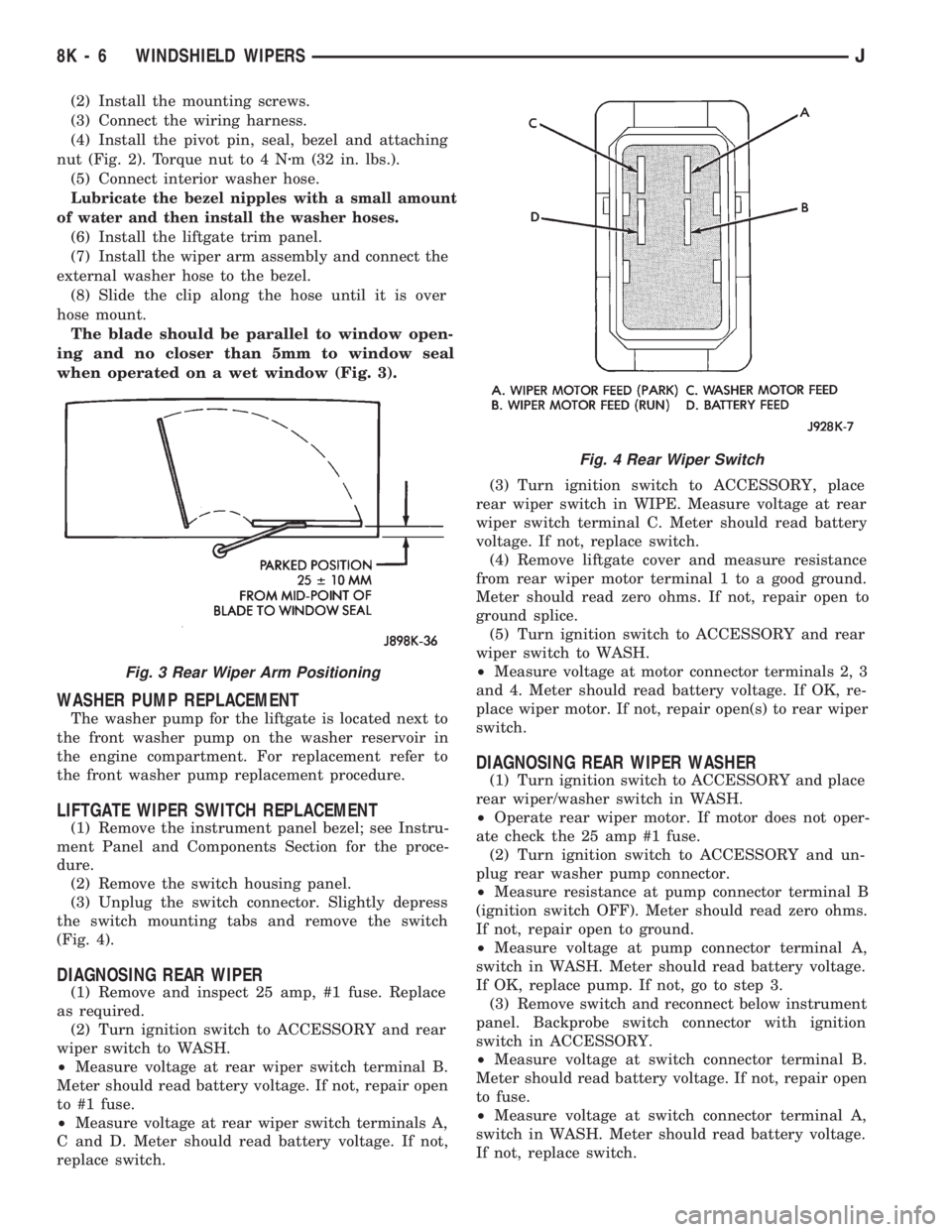
The blade should be parallel to window open-
ing and no closer than 5mm to window seal
when operated on a wet window (Fig. 3).
WASHER PUMP REPLACEMENT
The washer pump for the liftgate is located next to
the front washer pump on the washer reservoir in
the engine compartment. For replacement refer to
the front washer pump replacement procedure.
LIFTGATE WIPER SWITCH REPLACEMENT
(1) Remove the instrument panel bezel; see Instru-
ment Panel and Components Section for the proce-
dure.
(2) Remove the switch housing panel.
(3) Unplug the switch connector. Slightly depress
the switch mounting tabs and remove the switch
(Fig. 4).
DIAGNOSING REAR WIPER
(1) Remove and inspect 25 amp, #1 fuse. Replace
as required.
(2) Turn ignition switch to ACCESSORY and rear
wiper switch to WASH.
²Measure voltage at rear wiper switch terminal B.
Meter should read battery voltage. If not, repair open
to #1 fuse.
²Measure voltage at rear wiper switch terminals A,
C and D. Meter should read battery voltage. If not,
replace switch.(3) Turn ignition switch to ACCESSORY, place
rear wiper switch in WIPE. Measure voltage at rear
wiper switch terminal C. Meter should read battery
voltage. If not, replace switch.
(4) Remove liftgate cover and measure resistance
from rear wiper motor terminal 1 to a good ground.
Meter should read zero ohms. If not, repair open to
ground splice.
(5) Turn ignition switch to ACCESSORY and rear
wiper switch to WASH.
²Measure voltage at motor connector terminals 2, 3
and 4. Meter should read battery voltage. If OK, re-
place wiper motor. If not, repair open(s) to rear wiper
switch.
DIAGNOSING REAR WIPER WASHER
(1) Turn ignition switch to ACCESSORY and place
rear wiper/washer switch in WASH.
²Operate rear wiper motor. If motor does not oper-
ate check the 25 amp #1 fuse.
(2) Turn ignition switch to ACCESSORY and un-
plug rear washer pump connector.
²Measure resistance at pump connector terminal B
(ignition switch OFF). Meter should read zero ohms.
If not, repair open to ground.
²Measure voltage at pump connector terminal A,
switch in WASH. Meter should read battery voltage.
If OK, replace pump. If not, go to step 3.
(3) Remove switch and reconnect below instrument
panel. Backprobe switch connector with ignition
switch in ACCESSORY.
²Measure voltage at switch connector terminal B.
Meter should read battery voltage. If not, repair open
to fuse.
²Measure voltage at switch connector terminal A,
switch in WASH. Meter should read battery voltage.
If not, replace switch.
Fig. 3 Rear Wiper Arm Positioning
Fig. 4 Rear Wiper Switch
8K - 6 WINDSHIELD WIPERSJ
Page 764 of 1784
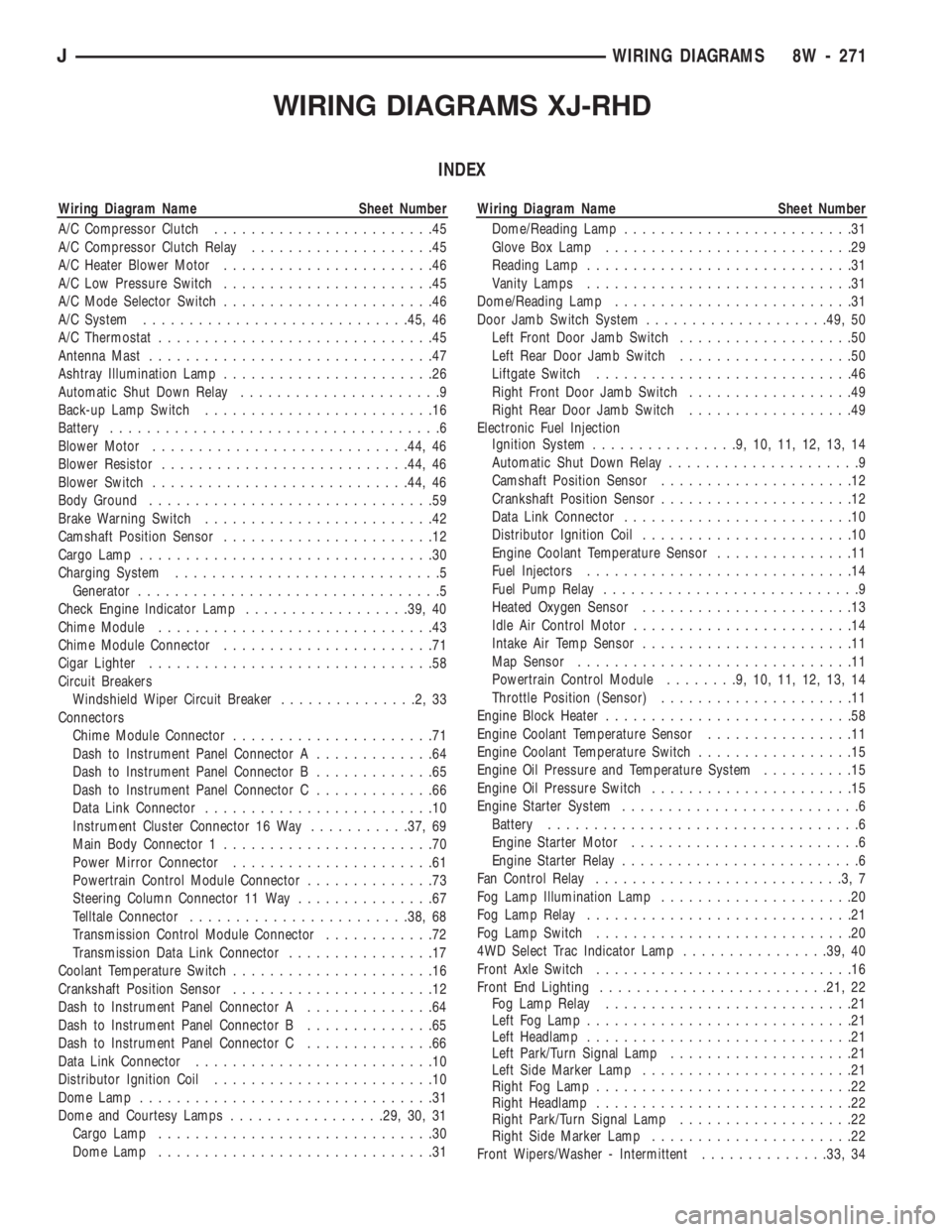
WIRING DIAGRAMS XJ-RHD
INDEX
Wiring Diagram Name Sheet Number
A/C Compressor Clutch........................45
A/C Compressor Clutch Relay....................45
A/C Heater Blower Motor.......................46
A/C Low Pressure Switch.......................45
A/C Mode Selector Switch.......................46
A/C System.............................45, 46
A/C Thermostat..............................45
Antenna Mast...............................47
Ashtray Illumination Lamp.......................26
Automatic Shut Down Relay......................9
Back-up Lamp Switch.........................16
Battery....................................6
Blower Motor............................44, 46
Blower Resistor...........................44, 46
Blower Switch............................44, 46
Body Ground...............................59
Brake Warning Switch.........................42
Camshaft Position Sensor.......................12
Cargo Lamp................................30
Charging System.............................5
Generator.................................5
Check Engine Indicator Lamp..................39, 40
Chime Module..............................43
Chime Module Connector.......................71
Cigar Lighter...............................58
Circuit Breakers
Windshield Wiper Circuit Breaker...............2,33
Connectors
Chime Module Connector......................71
Dash to Instrument Panel Connector A.............64
Dash to Instrument Panel Connector B.............65
Dash to Instrument Panel Connector C.............66
Data Link Connector.........................10
Instrument Cluster Connector 16 Way...........37, 69
Main Body Connector 1.......................70
Power Mirror Connector......................61
Powertrain Control Module Connector..............73
Steering Column Connector 11 Way...............67
Telltale Connector........................38, 68
Transmission Control Module Connector............72
Transmission Data Link Connector................17
Coolant Temperature Switch......................16
Crankshaft Position Sensor......................12
Dash to Instrument Panel Connector A..............64
Dash to Instrument Panel Connector B..............65
Dash to Instrument Panel Connector C..............66
Data Link Connector..........................10
Distributor Ignition Coil........................10
Dome Lamp................................31
Dome and Courtesy Lamps.................29, 30, 31
Cargo Lamp..............................30
Dome Lamp..............................31Wiring Diagram Name Sheet Number
Dome/Reading Lamp.........................31
Glove Box Lamp...........................29
Reading Lamp.............................31
Vanity Lamps.............................31
Dome/Reading Lamp..........................31
Door Jamb Switch System....................49, 50
Left Front Door Jamb Switch...................50
Left Rear Door Jamb Switch...................50
Liftgate Switch............................46
Right Front Door Jamb Switch..................49
Right Rear Door Jamb Switch..................49
Electronic Fuel Injection
Ignition System................9,10,11,12,13,14
Automatic Shut Down Relay.....................9
Camshaft Position Sensor.....................12
Crankshaft Position Sensor.....................12
Data Link Connector.........................10
Distributor Ignition Coil.......................10
Engine Coolant Temperature Sensor...............11
Fuel Injectors.............................14
Fuel Pump Relay............................9
Heated Oxygen Sensor.......................13
Idle Air Control Motor........................14
Intake Air Temp Sensor.......................11
Map Sensor..............................11
Powertrain Control Module........9,10,11,12,13,14
Throttle Position (Sensor).....................11
Engine Block Heater...........................58
Engine Coolant Temperature Sensor................11
Engine Coolant Temperature Switch.................15
Engine Oil Pressure and Temperature System..........15
Engine Oil Pressure Switch......................15
Engine Starter System..........................6
Battery..................................6
Engine Starter Motor.........................6
Engine Starter Relay..........................6
Fan Control Relay...........................3,7
Fog Lamp Illumination Lamp.....................20
Fog Lamp Relay.............................21
Fog Lamp Switch............................20
4WD Select Trac Indicator Lamp................39, 40
Front Axle Switch............................16
Front End Lighting.........................21, 22
Fog Lamp Relay...........................21
Left Fog Lamp.............................21
Left Headlamp.............................21
Left Park/Turn Signal Lamp....................21
Left Side Marker Lamp.......................21
Right Fog Lamp............................22
Right Headlamp............................22
Right Park/Turn Signal Lamp...................22
Right Side Marker Lamp......................22
Front Wipers/Washer - Intermittent..............33, 34
JWIRING DIAGRAMS 8W - 271
Page 765 of 1784
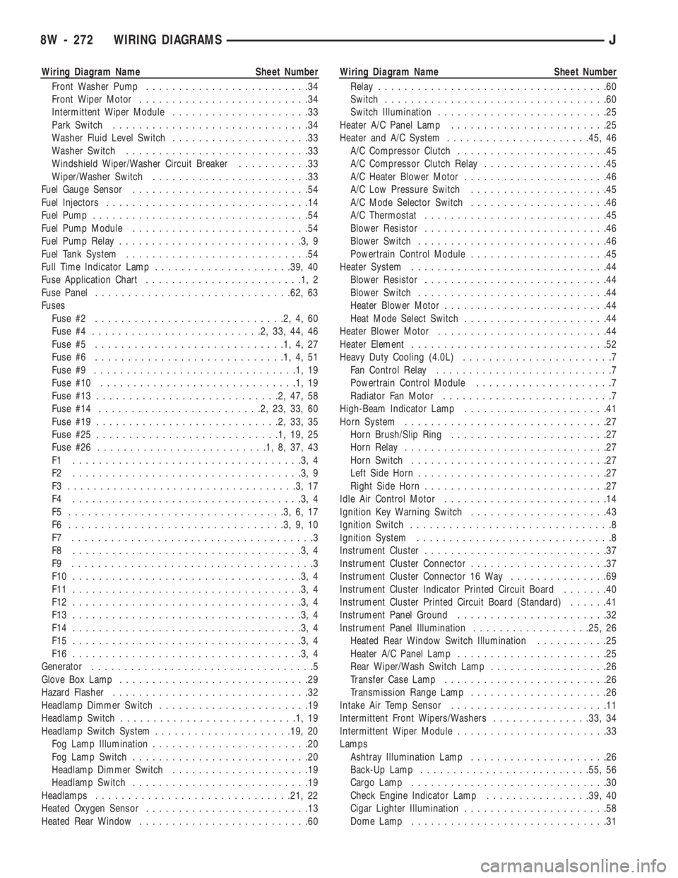
Wiring Diagram Name Sheet Number
Front Washer Pump.........................34
Front Wiper Motor..........................34
Intermittent Wiper Module.....................33
Park Switch..............................34
Washer Fluid Level Switch.....................33
Washer Switch............................33
Windshield Wiper/Washer Circuit Breaker...........33
Wiper/Washer Switch........................33
Fuel Gauge Sensor...........................54
Fuel Injectors...............................14
Fuel Pump.................................54
Fuel Pump Module...........................54
Fuel Pump Relay............................3,9
Fuel Tank System............................54
Full Time Indicator Lamp.....................39, 40
Fuse Application Chart........................1,2
Fuse Panel..............................62, 63
Fuses
Fuse #2.............................2,4,60
Fuse #4..........................2,33,44,46
Fuse #5.............................1,4,27
Fuse #6.............................1,4,51
Fuse #9...............................1,19
Fuse #10..............................1,19
Fuse #13............................2,47,58
Fuse #14.........................2,23,33,60
Fuse #19............................2,33,35
Fuse #25............................1,19,25
Fuse #26..........................1,8,37,43
F1 ...................................3,4
F2 ...................................3,9
F3 ...................................3,17
F4 ...................................3,4
F5 .................................3,6,17
F6 .................................3,9,10
F7 .....................................3
F8 ...................................3,4
F9 .....................................3
F10 ...................................3,4
F11 ...................................3,4
F12 ...................................3,4
F13 ...................................3,4
F14 ...................................3,4
F15 ...................................3,4
F16 ...................................3,4
Generator..................................5
Glove Box Lamp.............................29
Hazard Flasher..............................32
Headlamp Dimmer Switch.......................19
Headlamp Switch...........................1,19
Headlamp Switch System.....................19, 20
Fog Lamp Illumination........................20
Fog Lamp Switch...........................20
Headlamp Dimmer Switch.....................19
Headlamp Switch...........................19
Headlamps..............................21, 22
Heated Oxygen Sensor.........................13
Heated Rear Window..........................60Wiring Diagram Name Sheet Number
Relay...................................60
Switch..................................60
Switch Illumination..........................25
Heater A/C Panel Lamp........................25
Heater and A/C System......................45, 46
A/C Compressor Clutch.......................45
A/C Compressor Clutch Relay...................45
A/C Heater Blower Motor......................46
A/C Low Pressure Switch.....................45
A/C Mode Selector Switch.....................46
A/C Thermostat............................45
Blower Resistor............................46
Blower Switch.............................46
Powertrain Control Module.....................45
Heater System..............................44
Blower Resistor............................44
Blower Switch.............................44
Heater Blower Motor.........................44
Heat Mode Select Switch......................44
Heater Blower Motor..........................44
Heater Element..............................52
Heavy Duty Cooling (4.0L).......................7
Fan Control Relay...........................7
Powertrain Control Module.....................7
Radiator Fan Motor..........................7
High-Beam Indicator Lamp......................41
Horn System...............................27
Horn Brush/Slip Ring........................27
Horn Relay...............................27
Horn Switch..............................27
Left Side Horn.............................27
Right Side Horn............................27
Idle Air Control Motor.........................14
Ignition Key Warning Switch.....................43
Ignition Switch...............................8
Ignition System..............................8
Instrument Cluster............................37
Instrument Cluster Connector.....................37
Instrument Cluster Connector 16 Way...............69
Instrument Cluster Indicator Printed Circuit Board.......40
Instrument Cluster Printed Circuit Board (Standard)......41
Instrument Panel Ground.......................32
Instrument Panel Illumination..................25, 26
Heated Rear Window Switch Illumination...........25
Heater A/C Panel Lamp.......................25
Rear Wiper/Wash Switch Lamp..................26
Transfer Case Lamp.........................26
Transmission Range Lamp.....................26
Intake Air Temp Sensor........................11
Intermittent Front Wipers/Washers...............33, 34
Intermittent Wiper Module.......................33
Lamps
Ashtray Illumination Lamp.....................26
Back-Up Lamp..........................55, 56
Cargo Lamp..............................30
Check Engine Indicator Lamp................39, 40
Cigar Lighter Illumination......................58
Dome Lamp..............................31
8W - 272 WIRING DIAGRAMSJ