1994 JEEP CHEROKEE check engine
[x] Cancel search: check enginePage 860 of 1784
(3) Connect the CCV hoses (Fig. 1).
(4) Connect negative cable to battery.
ROCKER ARMS
This procedure can be done with the engine in or
out of the vehicle.
REMOVAL
(1) Remove the engine cylinder head cover.
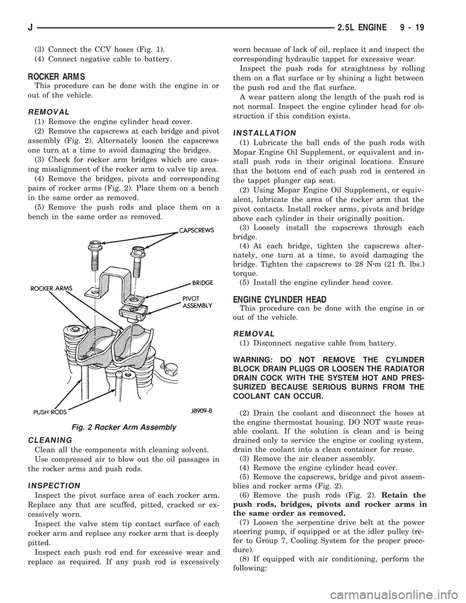
(2) Remove the capscrews at each bridge and pivot
assembly (Fig. 2). Alternately loosen the capscrews
one turn at a time to avoid damaging the bridges.
(3) Check for rocker arm bridges which are caus-
ing misalignment of the rocker arm to valve tip area.
(4) Remove the bridges, pivots and corresponding
pairs of rocker arms (Fig. 2). Place them on a bench
in the same order as removed.
(5) Remove the push rods and place them on a
bench in the same order as removed.
CLEANING
Clean all the components with cleaning solvent.
Use compressed air to blow out the oil passages in
the rocker arms and push rods.
INSPECTION
Inspect the pivot surface area of each rocker arm.
Replace any that are scuffed, pitted, cracked or ex-
cessively worn.
Inspect the valve stem tip contact surface of each
rocker arm and replace any rocker arm that is deeply
pitted.
Inspect each push rod end for excessive wear and
replace as required. If any push rod is excessivelyworn because of lack of oil, replace it and inspect the
corresponding hydraulic tappet for excessive wear.
Inspect the push rods for straightness by rolling
them on a flat surface or by shining a light between
the push rod and the flat surface.
A wear pattern along the length of the push rod is
not normal. Inspect the engine cylinder head for ob-
struction if this condition exists.
INSTALLATION
(1) Lubricate the ball ends of the push rods with
Mopar Engine Oil Supplement, or equivalent and in-
stall push rods in their original locations. Ensure
that the bottom end of each push rod is centered in
the tappet plunger cap seat.
(2) Using Mopar Engine Oil Supplement, or equiv-
alent, lubricate the area of the rocker arm that the
pivot contacts. Install rocker arms, pivots and bridge
above each cylinder in their originally position.
(3) Loosely install the capscrews through each
bridge.
(4) At each bridge, tighten the capscrews alter-
nately, one turn at a time, to avoid damaging the
bridge. Tighten the capscrews to 28 Nzm (21 ft. lbs.)
torque.
(5) Install the engine cylinder head cover.
ENGINE CYLINDER HEAD
This procedure can be done with the engine in or
out of the vehicle.
REMOVAL
(1) Disconnect negative cable from battery.
WARNING: DO NOT REMOVE THE CYLINDER
BLOCK DRAIN PLUGS OR LOOSEN THE RADIATOR
DRAIN COCK WITH THE SYSTEM HOT AND PRES-
SURIZED BECAUSE SERIOUS BURNS FROM THE
COOLANT CAN OCCUR.
(2) Drain the coolant and disconnect the hoses at
the engine thermostat housing. DO NOT waste reus-
able coolant. If the solution is clean and is being
drained only to service the engine or cooling system,
drain the coolant into a clean container for reuse.
(3) Remove the air cleaner assembly.
(4) Remove the engine cylinder head cover.
(5) Remove the capscrews, bridge and pivot assem-
blies and rocker arms (Fig. 2).
(6) Remove the push rods (Fig. 2).Retain the
push rods, bridges, pivots and rocker arms in
the same order as removed.
(7) Loosen the serpentine drive belt at the power
steering pump, if equipped or at the idler pulley (re-
fer to Group 7, Cooling System for the proper proce-
dure).
(8) If equipped with air conditioning, perform the
following:
Fig. 2 Rocker Arm Assembly
J2.5L ENGINE 9 - 19
Page 861 of 1784

(a) Remove the bolts from the A/C compressor
mounting bracket and set the compressor aside.
(b) Remove the air conditioner compressor
bracket bolts from the engine cylinder head.
(c) Loosen the through bolt at the bottom of the
bracket.
(9) If equipped, disconnect the power steering
pump bracket. Set the pump and bracket aside. DO
NOT disconnect the hoses.
(10) Remove the fuel lines and vacuum advance
hose.
(11) Remove the intake and engine exhaust mani-
folds from the engine cylinder head (refer to Group
11, Exhaust System and Intake Manifold for the
proper procedures).
(12) Disconnect the ignition wires and remove the
spark plugs.
(13) Disconnect the temperature sending unit wire
connector.
(14) Remove the ignition coil and bracket assem-
bly.
(15) Remove the engine cylinder head bolts.
(16) Remove the engine cylinder head and gasket
(Fig. 3).
(17) If this was the first time the bolts were re-
moved, put a paint dab on the top of the bolt. If the
bolts have a paint dab on the top of the bolt or it
isn't known if they were used before, discard the
bolts.
(18) Stuff clean lint free shop towels into the cyl-
inder bores.
CLEANING
Thoroughly clean the engine cylinder head and cyl-
inder block mating surfaces. Clean the intake and
exhaust manifold and engine cylinder head mating
surfaces. Remove all gasket material and carbon.
Check to ensure that no coolant or foreign material
has fallen into the tappet bore area.
Remove the carbon deposits from the combustion
chambers and top of the pistons.
INSPECTION
Use a straightedge and feeler gauge to check the
flatness of the engine cylinder head and block mat-
ing surfaces.
INSTALLATION
The engine cylinder head gasket is a composition
gasket. The gasket is to be installed DRY.DO NOT
use a gasket sealing compound on the gasket.
If the engine cylinder head is to be replaced and
the original valves used, measure the valve stem di-
ameter. Only standard size valves can be used with a
service replacement engine cylinder head unless the
replacement head valve stem guide bores are reamed
to accommodate oversize valve stems. Remove all
carbon buildup and reface the valves.
(1) Fabricate two engine cylinder head alignment
dowels from used head bolts (Fig. 4). Use the longest
head bolt. Cut the head of the bolt off below the hex
head. Then cut a slot in the top of the dowel to allow
easier removal with a screwdriver.
(2) Install one dowel in bolt hole No.10 and the
other dowel in bolt hole No.8 (Fig. 5).
(3) Remove the shop towels from the cylinder
bores. Coat the bores with clean engine oil.
(4) Place the engine cylinder head gasket (with the
numbers facing up) over the dowels.
Fig. 3 Engine Cylinder Head Assembly
Fig. 4 Fabricate Alignment Dowels
Fig. 5 Alignment Dowel Locations
9 - 20 2.5L ENGINEJ
Page 862 of 1784

(5) Place the engine cylinder head over the dowels.
CAUTION: Engine cylinder head bolts should be re-
used only once. Replace the head bolts if they were
used before or if they have a paint dab on the top
of the bolt.
(6) Coat the threads of bolt No.7, only, with Loctite
PST sealant or equivalent.
(7) Install all head bolts, except No.8 and No.10.
(8) Remove the dowels.
(9) Install No.8 and No.10 head bolts.
(10) Tighten the engine cylinder head bolts in se-
quence according to the following procedure (Fig. 6):
(a) Tighten all bolts in sequence (1 through 10)
to 30 Nzm (22 ft. lbs.) torque.
(b) Tighten all bolts in sequence (1 through 10)
to 61 Nzm (45 ft. lbs.) torque.
(c) Check all bolts to verify they are set to 61
Nzm (45 ft. lbs.) torque.
(d) Tighten bolts (in sequence):
²Bolts 1 through 6 to 149 Nzm (110 ft. lbs.) torque.
²Bolt 7 to 136 Nzm (100 ft. lbs.) torque.
²Bolts 8 through 10 to 149 Nzm (110 ft. lbs.) torque.
CAUTION: During the final tightening sequence,
bolt No.7 will be tightened to a lower torque than
the rest of the bolts. DO NOT overtighten bolt No.7.
(e) Check all bolts in sequence to verify the cor-
rect torque.
(f) If not already done, clean and mark each bolt
with a dab of paint after tightening. Should you
encounter bolts which were painted in an earlier
service operation, replace them.
(11) Install the ignition coil and bracket assembly.
(12) Connect the temperature sending unit wire
connector.
(13) Install the spark plugs and tighten to 37 Nzm
(27 ft. lbs.) torque. Connect the ignition wires.(14) Install the intake and exhaust manifolds (re-
fer to Group 11, Exhaust System and Intake Mani-
fold for the proper procedures).
(15) Install the fuel lines and the vacuum advance
hose.
(16) If equipped, attach the power steering pump
and bracket.
(17) Install the push rods, rocker arms, pivots and
bridges in the order they were removed.
(18) Install the engine cylinder head cover.
(19) Attach the air conditioning compressor mount-
ing bracket to the engine cylinder head and block.
Tighten the bolts to 40 Nzm (30 ft. lbs.) torque.
(20) Attach the air conditioning compressor to the
bracket. Tighten the bolts to 27 Nzm (20 ft. lbs.)
torque.
CAUTION: The serpentine drive belt must be routed
correctly. Incorrect routing can cause the water
pump to turn in the opposite direction causing the
engine to overheat.
(21) Install the serpentine drive belt and correctly
tension the belt (refer to Group 7, Cooling System for
the proper procedure).
(22) Install the air cleaner and ducting.
(23) Install the engine cylinder head cover.
(24) Connect the hoses to the thermostat housing
and fill the cooling system to the specified level (re-
fer to Group 7, Cooling Systems for the proper proce-
dure).
(25) The automatic transmission throttle linkage
and cable must be adjusted after completing the en-
gine cylinder head installation (refer to Group 21,
Transmissions for the proper procedures).
(26) Install the temperature sending unit and con-
nect the wire connector.
(27) Connect the fuel pipe and vacuum advance
hose.
(28) Connect negative cable to battery.
(29) Connect the upper radiator hose and heater
hose at the thermostat housing.
(30) Fill the cooling system. Check for leaks.
WARNING: USE EXTREME CAUTION WHEN THE
ENGINE IS OPERATING. DO NOT STAND IN DIRECT
LINE WITH THE FAN. DO NOT PUT HANDS NEAR
THE PULLEYS, BELTS OR FAN. DO NOT WEAR
LOOSE CLOTHING.
(31) Operate the engine with the radiator cap off.
Inspect for leaks and continue operating the engine
until the thermostat opens. Add coolant, if required.
VALVE SPRINGS AND OIL SEALS
This procedure can be done with the engine cylin-
der head installed on the block.
Fig. 6 Engine cylinder head Bolt Tightening
Sequence
J2.5L ENGINE 9 - 21
Page 873 of 1784
INSTALLATION
(1) Clean the camshaft pin hole.
(2) Compress the center of the replacement spring
pin with vise grips.
(3) Carefully drive the pin into the camshaft pin
hole until it is seated.
(4) Install the camshaft sprocket, crankshaft
sprocket and timing chain with the timing marks
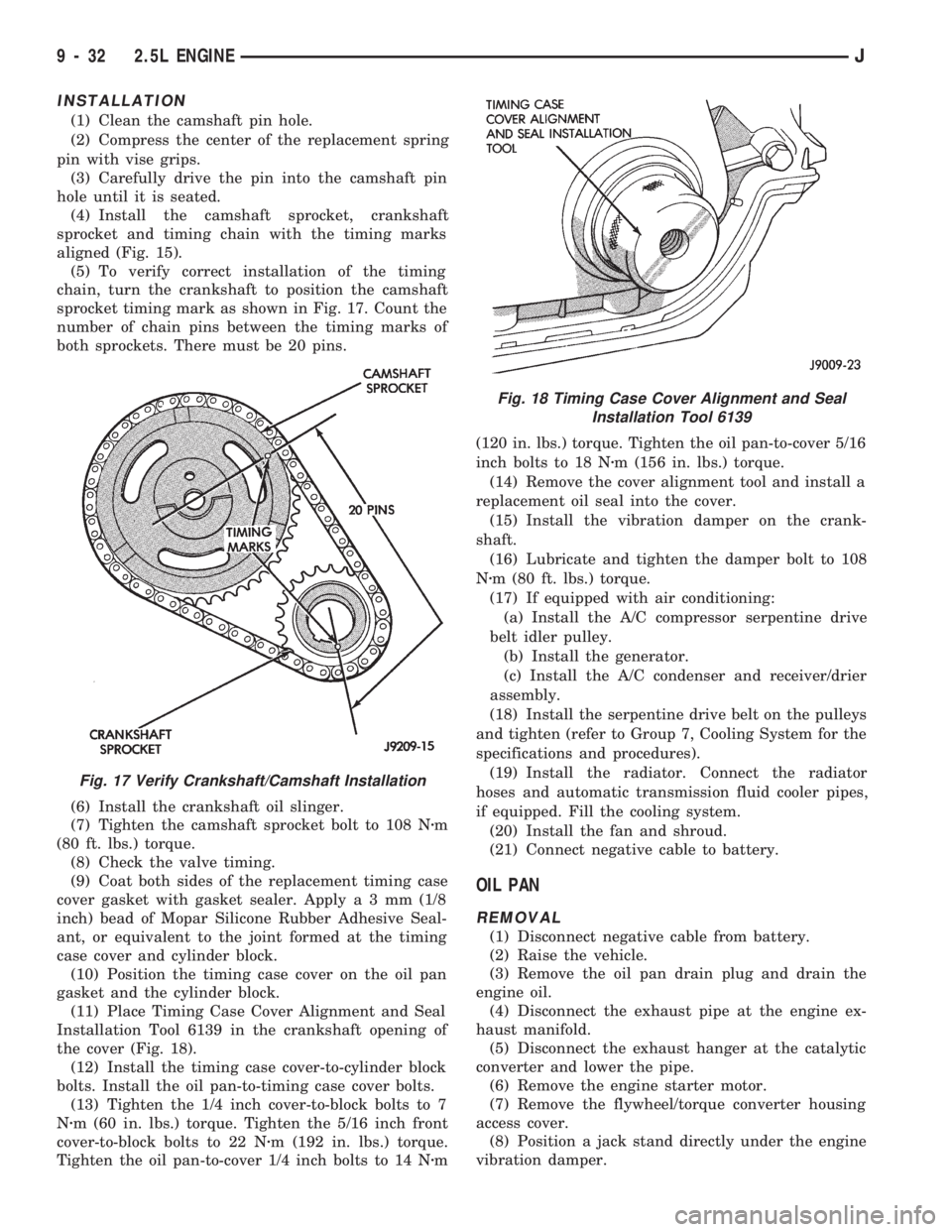
aligned (Fig. 15).
(5) To verify correct installation of the timing
chain, turn the crankshaft to position the camshaft
sprocket timing mark as shown in Fig. 17. Count the
number of chain pins between the timing marks of
both sprockets. There must be 20 pins.
(6) Install the crankshaft oil slinger.
(7) Tighten the camshaft sprocket bolt to 108 Nzm
(80 ft. lbs.) torque.
(8) Check the valve timing.
(9) Coat both sides of the replacement timing case
cover gasket with gasket sealer. Applya3mm(1/8
inch) bead of Mopar Silicone Rubber Adhesive Seal-
ant, or equivalent to the joint formed at the timing
case cover and cylinder block.
(10) Position the timing case cover on the oil pan
gasket and the cylinder block.
(11) Place Timing Case Cover Alignment and Seal
Installation Tool 6139 in the crankshaft opening of
the cover (Fig. 18).
(12) Install the timing case cover-to-cylinder block
bolts. Install the oil pan-to-timing case cover bolts.
(13) Tighten the 1/4 inch cover-to-block bolts to 7
Nzm (60 in. lbs.) torque. Tighten the 5/16 inch front
cover-to-block bolts to 22 Nzm (192 in. lbs.) torque.
Tighten the oil pan-to-cover 1/4 inch bolts to 14 Nzm(120 in. lbs.) torque. Tighten the oil pan-to-cover 5/16
inch bolts to 18 Nzm (156 in. lbs.) torque.
(14) Remove the cover alignment tool and install a
replacement oil seal into the cover.
(15) Install the vibration damper on the crank-
shaft.
(16) Lubricate and tighten the damper bolt to 108
Nzm (80 ft. lbs.) torque.
(17) If equipped with air conditioning:
(a) Install the A/C compressor serpentine drive
belt idler pulley.
(b) Install the generator.
(c) Install the A/C condenser and receiver/drier
assembly.
(18) Install the serpentine drive belt on the pulleys
and tighten (refer to Group 7, Cooling System for the
specifications and procedures).
(19) Install the radiator. Connect the radiator
hoses and automatic transmission fluid cooler pipes,
if equipped. Fill the cooling system.
(20) Install the fan and shroud.
(21) Connect negative cable to battery.
OIL PAN
REMOVAL
(1) Disconnect negative cable from battery.
(2) Raise the vehicle.
(3) Remove the oil pan drain plug and drain the
engine oil.
(4) Disconnect the exhaust pipe at the engine ex-
haust manifold.
(5) Disconnect the exhaust hanger at the catalytic
converter and lower the pipe.
(6) Remove the engine starter motor.
(7) Remove the flywheel/torque converter housing
access cover.
(8) Position a jack stand directly under the engine
vibration damper.
Fig. 17 Verify Crankshaft/Camshaft Installation
Fig. 18 Timing Case Cover Alignment and Seal
Installation Tool 6139
9 - 32 2.5L ENGINEJ
Page 875 of 1784
(75 psi). In the relief position, the valve permits oil
to bypass through a passage in the pump body to the
inlet side of the pump.
Oil pump removal or replacement will not affect
the distributor timing because the distributor drive
gear remains in mesh with the camshaft gear.
REMOVAL
(1) Drain the engine oil.
(2) Remove the oil pan.
(3) Remove the pump-to-cylinder block attaching
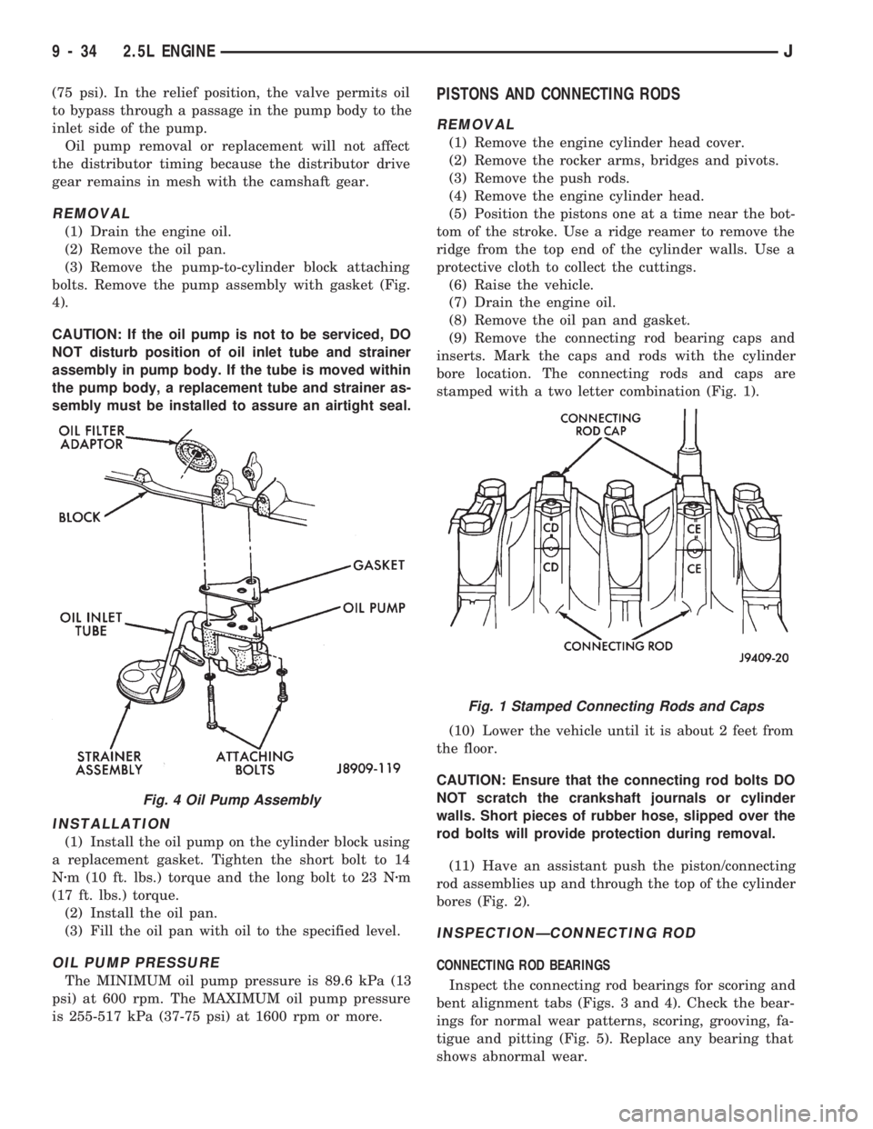
bolts. Remove the pump assembly with gasket (Fig.
4).
CAUTION: If the oil pump is not to be serviced, DO
NOT disturb position of oil inlet tube and strainer
assembly in pump body. If the tube is moved within
the pump body, a replacement tube and strainer as-
sembly must be installed to assure an airtight seal.
INSTALLATION
(1) Install the oil pump on the cylinder block using
a replacement gasket. Tighten the short bolt to 14
Nzm (10 ft. lbs.) torque and the long bolt to 23 Nzm
(17 ft. lbs.) torque.
(2) Install the oil pan.
(3) Fill the oil pan with oil to the specified level.
OIL PUMP PRESSURE
The MINIMUM oil pump pressure is 89.6 kPa (13
psi) at 600 rpm. The MAXIMUM oil pump pressure
is 255-517 kPa (37-75 psi) at 1600 rpm or more.
PISTONS AND CONNECTING RODS
REMOVAL
(1) Remove the engine cylinder head cover.
(2) Remove the rocker arms, bridges and pivots.
(3) Remove the push rods.
(4) Remove the engine cylinder head.
(5) Position the pistons one at a time near the bot-
tom of the stroke. Use a ridge reamer to remove the
ridge from the top end of the cylinder walls. Use a
protective cloth to collect the cuttings.
(6) Raise the vehicle.
(7) Drain the engine oil.
(8) Remove the oil pan and gasket.
(9) Remove the connecting rod bearing caps and
inserts. Mark the caps and rods with the cylinder
bore location. The connecting rods and caps are
stamped with a two letter combination (Fig. 1).
(10) Lower the vehicle until it is about 2 feet from
the floor.
CAUTION: Ensure that the connecting rod bolts DO
NOT scratch the crankshaft journals or cylinder
walls. Short pieces of rubber hose, slipped over the
rod bolts will provide protection during removal.
(11) Have an assistant push the piston/connecting
rod assemblies up and through the top of the cylinder
bores (Fig. 2).
INSPECTIONÐCONNECTING ROD
CONNECTING ROD BEARINGS
Inspect the connecting rod bearings for scoring and
bent alignment tabs (Figs. 3 and 4). Check the bear-
ings for normal wear patterns, scoring, grooving, fa-
tigue and pitting (Fig. 5). Replace any bearing that
shows abnormal wear.
Fig. 4 Oil Pump Assembly
Fig. 1 Stamped Connecting Rods and Caps
9 - 34 2.5L ENGINEJ
Page 883 of 1784
BEARING-TO-JOURNAL CLEARANCE (CRANKSHAFT
INSTALLED)
When using Plastigage, check only one bearing
clearance at a time.
Install the grooved main bearings into the cylinder
block and the non-grooved bearings into the bearing
caps.
Install the crankshaft into the upper bearings dry.
Place a strip of Plastigage across full width of the
crankshaft journal to be checked.
Install the bearing cap and tighten the bolts to 108
Nzm (80 ft. lbs.) torque.
DO NOT rotate the crankshaft. This will cause
the Plastigage to shift, resulting in an inaccurate
reading. Plastigage must not be permitted to
crumble. If brittle, obtain fresh stock.
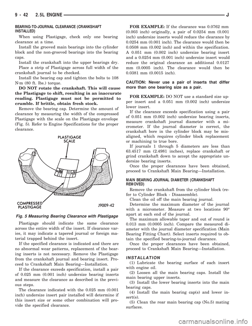
Remove the bearing cap. Determine the amount of
clearance by measuring the width of the compressed
Plastigage with the scale on the Plastigage envelope
(Fig. 5). Refer to Engine Specifications for the proper
clearance.
Plastigage should indicate the same clearance
across the entire width of the insert. If clearance var-
ies, it may indicate a tapered journal or foreign ma-
terial trapped behind the insert.
If the specified clearance is indicated and there are
no abnormal wear patterns, replacement of the bear-
ing inserts is not necessary. Remove the Plastigage
from the crankshaft journal and bearing insert. Pro-
ceed to Crankshaft Main BearingÐInstallation.
If the clearance exceeds specification, install a pair
of 0.025 mm (0.001 inch) undersize bearing inserts
and measure the clearance as described in the previ-
ous steps.
The clearance indicated with the 0.025 mm (0.001
inch) undersize insert pair installed will determine if
this insert size or some other combination will pro-
vide the specified clearance.FOR EXAMPLE:If the clearance was 0.0762 mm
(0.003 inch) originally, a pair of 0.0254 mm (0.001
inch) undersize inserts would reduce the clearance by
0.0254 mm (0.001 inch). The clearance would then be
0.0508 mm (0.002 inch) and within the specification.
A 0.051 mm (0.002 inch) undersize bearing insert
and a 0.0254 mm (0.001 inch) undersize insert would
reduce the original clearance an additional 0.0127
mm (0.0005 inch). The clearance would then be
0.0381 mm (0.0015 inch).
CAUTION: Never use a pair of inserts that differ
more than one bearing size as a pair.
FOR EXAMPLE:DO NOT use a standard size up-
per insert and a 0.051 mm (0.002 inch) undersize
lower insert.
If the clearance exceeds specification using a pair
of 0.051 mm (0.002 inch) undersize bearing inserts,
measure crankshaft journal diameter with a mi-
crometer. If the journal diameter is correct, the
crankshaft bore in the cylinder block may be mis-
aligned, which requires cylinder block replacement
or machining to true bore.
If journals 1 through 5 diameters are less than
63.4517 mm (2.4981 inches), replace crankshaft or
grind crankshaft down to accept the appropriate un-
dersize bearing inserts.
Once the proper clearances have been obtained,
proceed to Crankshaft Main BearingÐInstallation.
MAIN BEARING JOURNAL DIAMETER (CRANKSHAFT
REMOVED)
Remove the crankshaft from the cylinder block (re-
fer to Cylinder Block - Disassemble).
Clean the oil off the main bearing journal.
Determine the maximum diameter of the journal
with a micrometer. Measure at two locations 90É
apart at each end of the journal.
The maximum allowable taper and out of round is
0.013 mm (0.0005 inch). Compare the measured di-
ameter with the journal diameter specification (Main
Bearing Fitting Chart). Select inserts required to ob-
tain the specified bearing-to-journal clearance.
Once the proper clearances have been obtained,
proceed to Crankshaft Main BearingÐInstallation.
INSTALLATION
(1) Lubricate the bearing surface of each insert
with engine oil.
(2) Loosen all the main bearing caps. Install the
main bearing upper inserts.
(3) Install the lower bearing inserts into the main
bearing caps.
(4) Install the main bearing cap(s) and lower in-
sert(s).
(5) Clean the rear main bearing cap (No.5) mating
surfaces.
Fig. 5 Measuring Bearing Clearance with Plastigage
9 - 42 2.5L ENGINEJ
Page 885 of 1784

(6) Apply Loctite 515, or equivalent on the rear
bearing cap (Fig. 6). The bead should be 3 mm (0.125
in) thick. DO NOT apply Loctite 515, or equivalent
to the lip of the seal.
(7) Install the rear main bearing cap. DO NOT
strike the cap more than twice for proper engage-
ment.
(8) Tighten the bolts of caps 1, 3, 4 and 5 to 54
Nzm (40 ft. lbs.) torque. Now tighten these bolts to 95
Nzm (70 ft. lbs.) torque. Finally, tighten these bolts
to 108 Nzm (80 ft. lbs.) torque.
(9) Push the crankshaft forward and backward.
Load the crankshaft front or rear and tighten cap
bolt No.2 to 54 Nzm (40 ft. lbs.) torque. Then tighten
to 95 Nzm (70 ft. lbs.) torque and finally tighten to
108 Nzm (80 ft. lbs.) torque.
(10) Rotate the crankshaft after tightening each
main bearing cap to ensure the crankshaft rotates
freely.
(11) Check crankshaft end play. Crankshaft end
play is controlled by the thrust bearing which is
flange and installed at the No.2 main bearing posi-
tion.
(a) Attach a magnetic base dial indicator to the
cylinder block at either the front or rear of the en-
gine.
(b) Position the dial indicator rod so that it is
parallel to the center line of the crankshaft.
(c) Pry the crankshaft forward, position the dial
indicator to zero.
(d) Pry the crankshaft forward and backward.
Note the dial indicator readings. End play is the
difference between the high and low measurements
(Fig. 7). Correct end play is 0.038-0.165 mm(0.0015-0.0065 inch). The desired specifications are
0.051-0.064 mm (0.002-0.0025 inch).
(e) If end play is not within specification, inspect
crankshaft thrust faces for wear. If no wear is ap-
parent, replace the thrust bearing and measure end
play. If end play is still not within specification, re-
place the crankshaft.
If the crankshaft was removed, install the crank-
shaft into the cylinder block (refer to Cylinder Block -
Assemble).
(12) Install the oil pan.
(13) Install the drain plug. Tighten the plug to 34
Nzm (25 ft. lbs.) torque.
(14) Lower the vehicle.
(15) Install the spark plugs. Tighten the plugs to
37 Nzm (27 ft. lbs.) torque.
(16) Fill the oil pan with engine oil to the full
mark on the dipstick level.
(17) Connect negative cable to battery.
REAR MAIN OIL SEALS
REMOVAL
(1) Remove the flywheel or converter drive plate.
Discard the old bolts.
(2) Pry out the seal from around the crankshaft
flange (Fig. 8).
INSTALLATION
(1) Coat the outer lip of the replacement rear main
bearing seal with engine oil.
(2) Carefully position the seal into place. Use rear
main Seal Installer Tool 6271 to install the seal flush
with the cylinder block.
CAUTION: The felt lip must be located inside the
flywheel mounting surface. If the lip is not posi-
tioned correctly the flywheel could tear the seal.
Fig. 6 Location of Loctite 515 (or equivalent)
Fig. 7 Crankshaft End Play Measurement
9 - 44 2.5L ENGINEJ
Page 896 of 1784
(6) Remove upper radiator support retaining bolts
and remove radiator support.
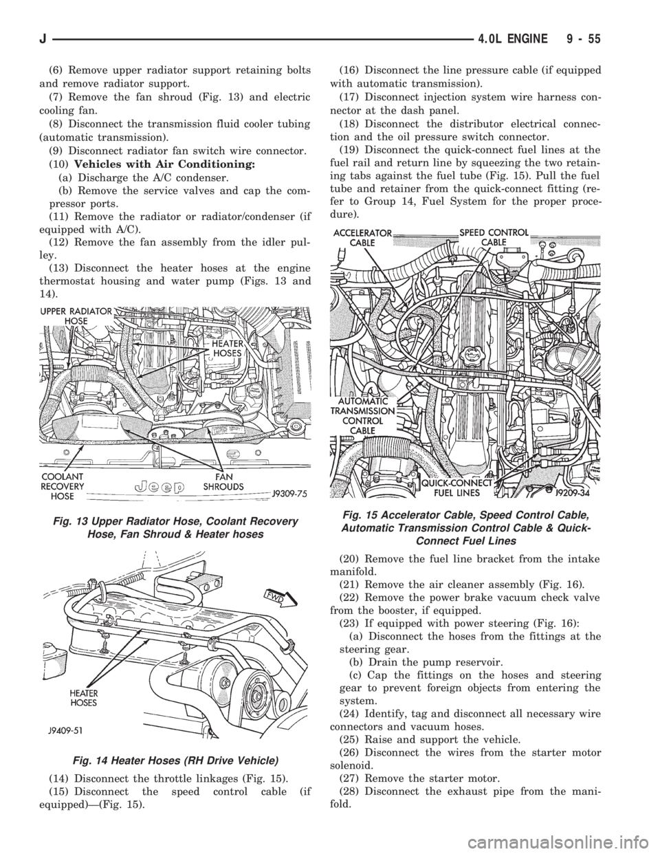
(7) Remove the fan shroud (Fig. 13) and electric
cooling fan.
(8) Disconnect the transmission fluid cooler tubing
(automatic transmission).
(9) Disconnect radiator fan switch wire connector.
(10)Vehicles with Air Conditioning:
(a) Discharge the A/C condenser.
(b) Remove the service valves and cap the com-
pressor ports.
(11) Remove the radiator or radiator/condenser (if
equipped with A/C).
(12) Remove the fan assembly from the idler pul-
ley.
(13) Disconnect the heater hoses at the engine
thermostat housing and water pump (Figs. 13 and
14).
(14) Disconnect the throttle linkages (Fig. 15).
(15) Disconnect the speed control cable (if
equipped)Ð(Fig. 15).(16) Disconnect the line pressure cable (if equipped
with automatic transmission).
(17) Disconnect injection system wire harness con-
nector at the dash panel.
(18) Disconnect the distributor electrical connec-
tion and the oil pressure switch connector.
(19) Disconnect the quick-connect fuel lines at the
fuel rail and return line by squeezing the two retain-
ing tabs against the fuel tube (Fig. 15). Pull the fuel
tube and retainer from the quick-connect fitting (re-
fer to Group 14, Fuel System for the proper proce-
dure).
(20) Remove the fuel line bracket from the intake
manifold.
(21) Remove the air cleaner assembly (Fig. 16).
(22) Remove the power brake vacuum check valve
from the booster, if equipped.
(23) If equipped with power steering (Fig. 16):
(a) Disconnect the hoses from the fittings at the
steering gear.
(b) Drain the pump reservoir.
(c) Cap the fittings on the hoses and steering
gear to prevent foreign objects from entering the
system.
(24) Identify, tag and disconnect all necessary wire
connectors and vacuum hoses.
(25) Raise and support the vehicle.
(26) Disconnect the wires from the starter motor
solenoid.
(27) Remove the starter motor.
(28) Disconnect the exhaust pipe from the mani-
fold.
Fig. 13 Upper Radiator Hose, Coolant Recovery
Hose, Fan Shroud & Heater hoses
Fig. 14 Heater Hoses (RH Drive Vehicle)
Fig. 15 Accelerator Cable, Speed Control Cable,
Automatic Transmission Control Cable & Quick-
Connect Fuel Lines
J4.0L ENGINE 9 - 55