Page 1315 of 1784
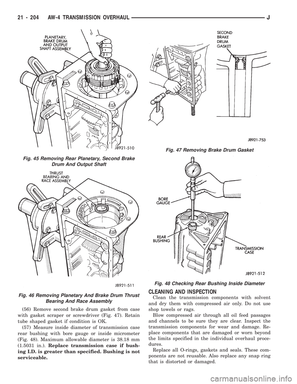
(56) Remove second brake drum gasket from case
with gasket scraper or screwdriver (Fig. 47). Retain
tube shaped gasket if condition is OK.
(57) Measure inside diameter of transmission case
rear bushing with bore gauge or inside micrometer
(Fig. 48). Maximum allowable diameter is 38.18 mm
(1.5031 in.).Replace transmission case if bush-
ing I.D. is greater than specified. Bushing is not
serviceable.
CLEANING AND INSPECTION
Clean the transmission components with solvent
and dry them with compressed air only. Do not use
shop towels or rags.
Blow compressed air through all oil feed passages
and channels to be sure they are clear. Inspect the
transmission components for wear and damage. Re-
place components that are damaged or worn beyond
the limits specified in the individual overhaul proce-
dures.
Replace all O-rings, gaskets and seals. These com-
ponents are not reusable. Also replace any snap ring
that is distorted or damaged.
Fig. 45 Removing Rear Planetary, Second Brake
Drum And Output Shaft
Fig. 46 Removing Planetary And Brake Drum Thrust
Bearing And Race Assembly
Fig. 47 Removing Brake Drum Gasket
Fig. 48 Checking Rear Bushing Inside Diameter
21 - 204 AW-4 TRANSMISSION OVERHAULJ
Page 1318 of 1784
(6) Measure inside diameter of stator shaft bush-
ing (Fig. 2). Take measurements at front and rear of
bushing. Diameter should be maximum of 21.58 mm
(0.08496 in.) at front and 27.08 mm (1.0661 in.) at
rear. Replace stator shaft if bushing diameter is
greater than specified.
(7) Measure oil pump clearances (Fig. 3).
²Clearance between pump driven gear and pump
body should be maximum of 0.3 mm (0.012 in).
²Clearance between tips of pump gear teeth should
be maximum of 0.3 mm (0.012 in).
²Clearance between rear surface of pump housing
and pump gears should be maximum of 0.1 mm
(0.004 in.).
(8) Replace pump body and gears if any clearance
is greater than specified.
Fig. 2 Checking Pump/Stator Shaft Bushings
Fig. 3 Checking Pump Gear Clearances
JAW-4 TRANSMISSION OVERHAUL 21 - 207
Page 1321 of 1784
(4) Measure stroke length of clutch piston as fol-
lows:
(a) Mount oil pump on torque converter. Then
mount clutch on oil pump (Fig. 5).
(b) Mount dial indicator on clutch and position
indicator stylus on clutch piston (Fig. 6).
(c) Apply compressed air through clutch feed hole
in oil pump and note piston stroke length. Stroke
length should be 1.85 - 2.15 mm (0.0728 - 0.0846
in.).
(5) Replace clutch pack retainer if stroke length is
incorrect. Refer to chart in Specifications section for
replacement retainer thicknesses.
Fig. 2 Checking One-Way Clutch
Fig. 3 Removing Overdrive Clutch From Gear
Fig. 4 Removing Clutch Drum Bearing And Race
Fig. 5 Assembling Converter, Pump And Clutch For
Test
21 - 210 AW-4 TRANSMISSION OVERHAULJ
Page 1322 of 1784
(6) Remove clutch pack snap ring and remove the
clutch pack.
(7) Compress piston return spring with Tool 7538
(Fig. 8). Remove snap ring and remove compressor
tool.
(8) Remove compressor tool and piston return
springs.
(9) Mount oil pump on converter. Then mount
clutch on oil pump (Fig. 9).
(10) Hold clutch piston by hand and apply com-
pressed air through oil pump feed hole to ease piston
out (Fig. 9). Apply only enough air pressure to re-
move piston.
Fig. 6 Checking Overdrive Clutch Piston Stroke
Fig. 7 Removing Clutch Pack Snap Ring
Fig. 8 Removing Clutch Piston Snap Ring
Fig. 9 Removing Overdrive Clutch Piston
JAW-4 TRANSMISSION OVERHAUL 21 - 211
Page 1349 of 1784
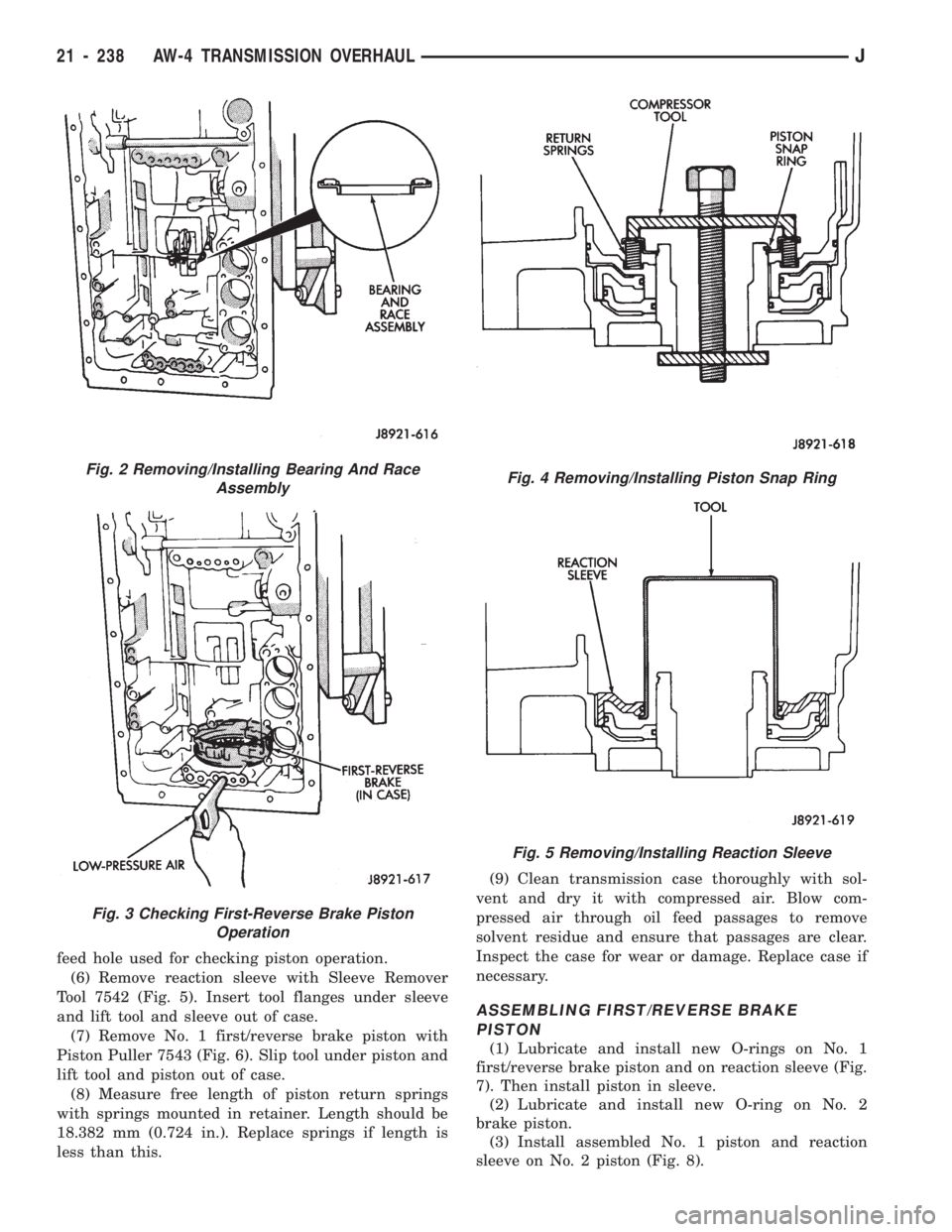
feed hole used for checking piston operation.
(6) Remove reaction sleeve with Sleeve Remover
Tool 7542 (Fig. 5). Insert tool flanges under sleeve
and lift tool and sleeve out of case.
(7) Remove No. 1 first/reverse brake piston with
Piston Puller 7543 (Fig. 6). Slip tool under piston and
lift tool and piston out of case.
(8) Measure free length of piston return springs
with springs mounted in retainer. Length should be
18.382 mm (0.724 in.). Replace springs if length is
less than this.(9) Clean transmission case thoroughly with sol-
vent and dry it with compressed air. Blow com-
pressed air through oil feed passages to remove
solvent residue and ensure that passages are clear.
Inspect the case for wear or damage. Replace case if
necessary.
ASSEMBLING FIRST/REVERSE BRAKE
PISTON
(1) Lubricate and install new O-rings on No. 1
first/reverse brake piston and on reaction sleeve (Fig.
7). Then install piston in sleeve.
(2) Lubricate and install new O-ring on No. 2
brake piston.
(3) Install assembled No. 1 piston and reaction
sleeve on No. 2 piston (Fig. 8).
Fig. 2 Removing/Installing Bearing And Race
Assembly
Fig. 3 Checking First-Reverse Brake Piston
Operation
Fig. 4 Removing/Installing Piston Snap Ring
Fig. 5 Removing/Installing Reaction Sleeve
21 - 238 AW-4 TRANSMISSION OVERHAULJ
Page 1357 of 1784
(8) Press regulator valve sleeve into bore and in-
stall retainer (Fig. 5 and 6). Be sure retainer is posi-
tioned in sleeve lugs as shown.
(9) Install 1-2 shift valve, spring and plug (Fig. 4).
Then press valve assembly into bore and install re-
tainer.
(10) Install replacement O-rings on solenoids and
install solenoids on valve body. Tighten solenoid at-
taching bolts to 10 Nzm (7 ft-lbs) torque.
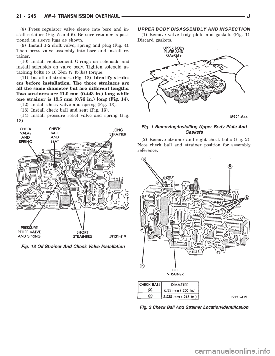
(11) Install oil strainers (Fig. 13).Identify strain-
ers before installation. The three strainers are
all the same diameter but are different lengths.
Two strainers are 11.0 mm (0.443 in.) long while
one strainer is 19.5 mm (0.76 in.) long (Fig. 14).
(12) Install check valve and spring (Fig. 13).
(13) Install check ball and seat (Fig. 13).
(14) Install pressure relief valve and spring (Fig.
13).UPPER BODY DISASSEMBLY AND INSPECTION
(1) Remove valve body plate and gaskets (Fig. 1).
Discard gaskets.
(2) Remove strainer and eight check balls (Fig. 2).
Note check ball and strainer position for assembly
reference.
Fig. 1 Removing/Installing Upper Body Plate And
Gaskets
Fig. 2 Check Ball And Strainer Location/Identification
Fig. 13 Oil Strainer And Check Valve Installation
21 - 246 AW-4 TRANSMISSION OVERHAULJ
Page 1363 of 1784
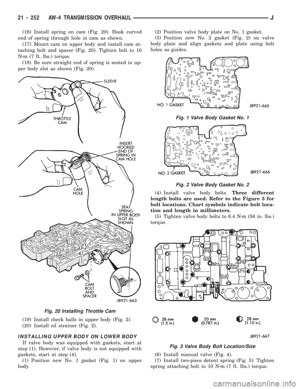
(16) Install spring on cam (Fig. 20). Hook curved
end of spring through hole in cam as shown.
(17) Mount cam on upper body and install cam at-
taching bolt and spacer (Fig. 20). Tighten bolt to 10
Nzm (7 ft. lbs.) torque.
(18) Be sure straight end of spring is seated in up-
per body slot as shown (Fig. 20).
(19) Install check balls in upper body (Fig. 2).
(20) Install oil strainer (Fig. 2).
INSTALLING UPPER BODY ON LOWER BODY
If valve body was equipped with gaskets, start at
step (1). However, if valve body is not equipped with
gaskets, start at step (4).
(1) Position new No. 1 gasket (Fig. 1) on upper
body.(2) Position valve body plate on No. 1 gasket.
(3) Position new No. 2 gasket (Fig. 2) on valve
body plate and align gaskets and plate using bolt
holes as guides.
(4) Install valve body bolts.Three different
length bolts are used. Refer to the Figure 3 for
bolt locations. Chart symbols indicate bolt loca-
tion and length in millimeters.
(5) Tighten valve body bolts to 6.4 Nzm (56 in. lbs.)
torque.
(6) Install manual valve (Fig. 4).
(7) Install two-piece detent spring (Fig. 5). Tighten
spring attaching bolt to 10 Nzm (7 ft. lbs.) torque.
Fig. 20 Installing Throttle Cam
Fig. 1 Valve Body Gasket No. 1
Fig. 2 Valve Body Gasket No. 2
Fig. 3 Valve Body Bolt Location/Size
21 - 252 AW-4 TRANSMISSION OVERHAULJ
Page 1378 of 1784
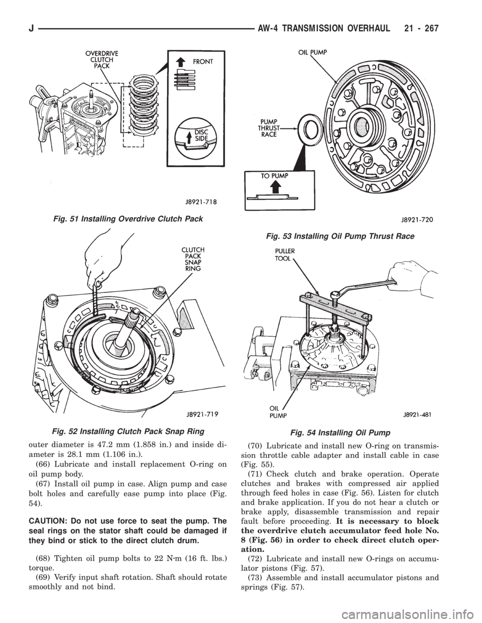
outer diameter is 47.2 mm (1.858 in.) and inside di-
ameter is 28.1 mm (1.106 in.).
(66) Lubricate and install replacement O-ring on
oil pump body.
(67) Install oil pump in case. Align pump and case
bolt holes and carefully ease pump into place (Fig.
54).
CAUTION: Do not use force to seat the pump. The
seal rings on the stator shaft could be damaged if
they bind or stick to the direct clutch drum.
(68) Tighten oil pump bolts to 22 Nzm (16 ft. lbs.)
torque.
(69) Verify input shaft rotation. Shaft should rotate
smoothly and not bind.(70) Lubricate and install new O-ring on transmis-
sion throttle cable adapter and install cable in case
(Fig. 55).
(71) Check clutch and brake operation. Operate
clutches and brakes with compressed air applied
through feed holes in case (Fig. 56). Listen for clutch
and brake application. If you do not hear a clutch or
brake apply, disassemble transmission and repair
fault before proceeding.It is necessary to block
the overdrive clutch accumulator feed hole No.
8 (Fig. 56) in order to check direct clutch oper-
ation.
(72) Lubricate and install new O-rings on accumu-
lator pistons (Fig. 57).
(73) Assemble and install accumulator pistons and
springs (Fig. 57).
Fig. 53 Installing Oil Pump Thrust Race
Fig. 54 Installing Oil Pump
Fig. 51 Installing Overdrive Clutch Pack
Fig. 52 Installing Clutch Pack Snap Ring
JAW-4 TRANSMISSION OVERHAUL 21 - 267