1994 JEEP CHEROKEE check oil
[x] Cancel search: check oilPage 1445 of 1784
TIRE CHAINS
Tire snow chains may be used on certain models.
Refer to Owner's Manual for more information.
CLEANING OF TIRES
Steam cleaning may be used for cleaning.
DO NOT use gasoline or wire brush for cleaning.
DO NOT use mineral oil or an oil-based solvent.
PRESSURE GAUGES
High-quality, dial-type, air-pressure gauges are
recommended. After checking with the gauge, re-
place valve cap and finger tight.
TIRE INFLATION PRESSURES
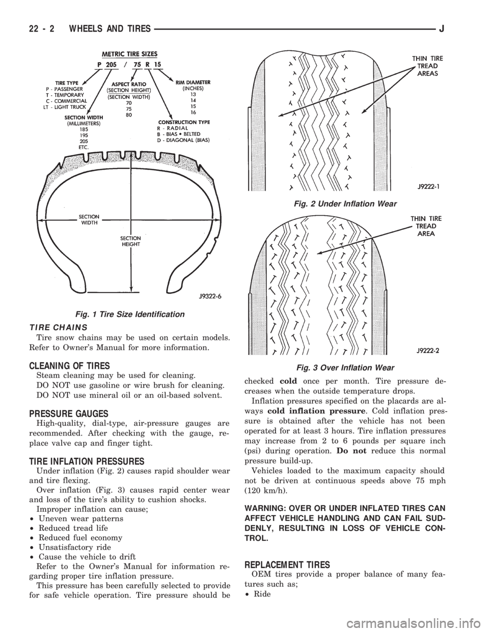
Under inflation (Fig. 2) causes rapid shoulder wear
and tire flexing.
Over inflation (Fig. 3) causes rapid center wear
and loss of the tire's ability to cushion shocks.
Improper inflation can cause;
²Uneven wear patterns
²Reduced tread life
²Reduced fuel economy
²Unsatisfactory ride
²Cause the vehicle to drift
Refer to the Owner's Manual for information re-
garding proper tire inflation pressure.
This pressure has been carefully selected to provide
for safe vehicle operation. Tire pressure should becheckedcoldonce per month. Tire pressure de-
creases when the outside temperature drops.
Inflation pressures specified on the placards are al-
wayscold inflation pressure. Cold inflation pres-
sure is obtained after the vehicle has not been
operated for at least 3 hours. Tire inflation pressures
may increase from 2 to 6 pounds per square inch
(psi) during operation.Do notreduce this normal
pressure build-up.
Vehicles loaded to the maximum capacity should
not be driven at continuous speeds above 75 mph
(120 km/h).
WARNING: OVER OR UNDER INFLATED TIRES CAN
AFFECT VEHICLE HANDLING AND CAN FAIL SUD-
DENLY, RESULTING IN LOSS OF VEHICLE CON-
TROL.
REPLACEMENT TIRES
OEM tires provide a proper balance of many fea-
tures such as;
²Ride
Fig. 1 Tire Size Identification
Fig. 2 Under Inflation Wear
Fig. 3 Over Inflation Wear
22 - 2 WHEELS AND TIRESJ
Page 1665 of 1784
WARNING: LARGE AMOUNTS OF REFRIGERANT
RELEASED IN A CLOSED WORK AREA WILL DIS-
PLACE THE OXYGEN AND CAUSE SUFFOCATION.
ALWAYS MAINTAIN GOOD VENTILATION SUR-
ROUNDING THE WORK AREA.
R-12 gas, under normal conditions, is non-poison-
ous.
WARNING: THE DISCHARGE OF R-12 GAS NEAR
AN OPEN FLAME CAN PRODUCE A VERY POISON-
OUS GAS CALLED PHOSGENE. PHOSGENE IS
GENERATED WHEN A FLAME-TYPE LEAK DETEC-
TOR IS USED.
CAUTION: When charging an A/C system always
keep the tank in an upright position. If the tank is
on its side or upside down, liquid refrigerant will
enter the system and may damage the compressor.
In most instances when charging or adding refrig-
erant, moderate heat is required to bring the pres-
sure of the refrigerant above the pressure of the
system. A bucket or large pan of hot water, not over
52ÉC (125ÉF), is all the heat required for this pur-
pose. DO NOT heat the refrigerant container with a
blow torch or any other means that would raise the
temperature and pressure above this temperature.
CAUTION: DO NOT allow liquid refrigerant to touch
bright metal. Refrigerant will tarnish bright metal
and chrome surfaces. Refrigerant in combination
with moisture is very corrosive and can cause ex-
tensive damage to all metal surfaces.
Avoid splashing the refrigerant on any surface.
RECYCLING
(R-12) refrigerant is a chloroflorocarbon (CFC) that
can contribute to the depletion of the ozone layer in
the upper atmosphere. Ozone filters out harmful ra-
diation from the sun. To assist in protecting the
ozone layer, Chrysler Corporation requires that an
(R-12) refrigerant recovery device that meets SAE
standard J1991 be used. Contact an automotive ser-
vice equipment supplier for refrigerant recycling
equipment that is available in your area. Refer to
the operating instructions provided with the recy-
cling equipment for proper operation.
SERVICE PRECAUTIONS
Never open or loosen a connection before discharg-
ing the system refrigerant.
A system which has been opened to replace a com-
ponent or one which has discharged through leakage
must be evacuated before charging.
Immediately after disconnecting a component from
the system, seal the open fittings with a cap or plug.Before disconnecting a component from the system,
clean the outside of the fittings thoroughly.
DO NOT remove the sealing caps from a replace-
ment component until ready to install.
Refrigerant oil will absorb moisture from the atmo-
sphere if left uncapped. DO NOT open an oil con-
tainer until ready to use and install the cap
immediately after using. Store the oil only in a clean
moisture-free container.
Before connecting an open fitting always install a
new seal ring. Coat the fitting and seal with clean
refrigerant oil before connecting.
When installing a refrigerant line avoid sharp
bends. Position the line away from the exhaust or
any sharp edges which may chafe the line.
Tighten fittings only to the specified torque. The
copper and aluminum fittings used in the A/C system
will not tolerate over tightening.
When disconnecting a fitting use a wrench on both
halves of the fitting to prevent twisting of the refrig-
erant lines or tubes.
DO NOT open a refrigerant system or uncap a re-
placement component unless it is as close as possible
to room temperature. This will prevent condensation
from forming inside of a component which is cooler
than the surrounding air.
Keep service tools and the work area clean. Con-
tamination of A/C system through careless work hab-
its must be avoided.
PRESSURE GAUGE AND MANIFOLD ASSEMBLY
Pressure Gauge and Manifold Assembly Tool
C-3740-B (Fig. 1) is the most important tool used to
service the air conditioning system. The gauge as-
sembly is used to determine:
²System high side gauge pressures
²System low side gauge pressures
²The correct refrigerant charge
²System diagnosis
It is designed to provide simultaneous high and low
side pressure indications, because these pressures
must be compared to determine the correct system
operation.
LOW SIDE GAUGE
The low side gauge is a compound gauge, which
means that it will register both pressure and vacuum
(Fig. 1). The compound gauge is calibrated 0-1034
kPa (0-150 psi) pressure and 0-760 mm (0-30 in.) of
mercury vacuum. It is connected to the suction ser-
vice valve to check the low side pressure or vacuum.
HIGH SIDE GAUGE
The high side gauge is used to check the pressure
in the discharge side of the air conditioning system
(Fig. 1).
24 - 2 HEATING AND AIR CONDITIONINGJ
Page 1668 of 1784
(2) Close all the hand valves.
(3) Connect the red charging hose to the discharge
service valve.
(4) Connect the blue charging hose to the inlet
(suction) service valve.
(5) Discharge the system. Leave the suction and
discharge service valves in the mid-position.
CAUTION: The system must be completely dis-
charged into a recovery device before evacuating. If
the system is still charged, refrigerant can enter
and damage the vacuum pump.
(6) Connect the vacuum pump hose to the vacuum
pump inlet.
(7) Open the low and high pressure control valves
on the charging station.
(8) Start the vacuum pump. Open the vacuum con-
trol valve and note the vacuum reading.
(9) Test the system for leaks as follows:
²Close the manifold hand valves.
²Stop the vacuum pump and observe the vacuum
reading.
²If the system is leak-free, vacuum will hold steady
at the level indicated when the pump was stopped. If
vacuum remains steady for 3-5 minutes, resume and
continue evacuation for a minimum of 30 minutes.
²If the system has a leak, vacuum will fall off or
rapidly drop to a 0 reading. If a leak exists, partially
charge the system. Find and repair the leak and re-
sume evacuation.
(10) Continue evacuating the system for a mini-
mum of 30 minutes after attaining the lowest vac-
uum level.
(11) Fill the station charging cylinder while the
system is evacuating.
(12) Close the vacuum control valve and stop the
vacuum pump.
(13) Observe low pressure gauge to determine if a
system leak exists. If the system is leak-free, the sys-
tem is now ready for charging.
SYSTEM CHARGE
CHARGE CAPACITY
The recommended system charge is 1.1 kg (38 oz.)
of R-12 refrigerant for XJ vehicles and 0.9 kg (32 oz.)
for YJ vehicles.
Add an additional 28 grams (1 fluid oz.) of
compressor oil to the system when a hose, re-
ceiver-drier, condenser, expansion valve or
evaporator core is replaced.
PORTABLE SERVICE STATION
(1) Fill the station charging cylinder. Refrigerant
should be observed rising in the cylinder sight glass.
(2) Slightly open the valve at the top of the cylin-
der when pressure in the charging cylinder and re-frigerant supply tank are equal. This relieves head
pressure allowing refrigerant to continue filling the
cylinder.
(3) Observe the pressure gauge at the top of the
cylinder. Rotate the plastic cover on the cylinder un-
til the pressure heading column corresponds with the
gauge pressure in-line with the sight glass.
FOR EXAMPLE:ÐThe pressure gauge at the top
of the cylinder indicates 483 kPa (70 psi). Locate the
column with the pressure heading of 483 (70) and ro-
tate the cover so the 483 (70) column aligns with the
sight glass.
(4) When refrigerant reaches the correct level in
the sight glass, close the right hand valve at cylinder
base and on the refrigerant drum.
(5) Close the valve at the top of the charging cyl-
inder.
(6) Check for bubbles in the refrigerant using the
cylinder sight glass. If bubbles appear in the refrig-
erant, tilt the charging station rearward momen-
tarily.
(7) Connect the heating element cord to the power
pack receptacle and turn the heater switch ON.
(8) Allow the refrigerant to warm for about 10
minutes while the vacuum pump is operating.
WARNING: WEAR GOGGLES TO PROTECT THE
EYES.
(9) Discharge and evacuate the system.
(10) Close the low pressure valve on the charging
station.
(11) Fully open the left hand refrigerant control
valve at the base of the cylinder and the high pres-
sure valve on the charging station.
(12) Charge the system.
(13) Close the refrigerant control valve and the
high pressure valve on the charging station.
CAUTION: DO NOT permit the liquid level to drop
below 0 on the cylinder sight glass.
(14) Close the manifold gauges after completion of
the charging operation and check the high and low
side pressures.
(15) Check system operation.
CAUTION: DO NOT check system pressures until
the high and low pressure valves on the charging
station are closed. The low pressure gauge could
be damaged if the valves are open.
(16) Close all the valves on the charging station
and close the refrigerant drum valve when all the op-
erations are completed.
(17) Back-seat the service valves by turning them
fully counterclockwise. Install the quick seal caps on
the valves afterward.
JHEATING AND AIR CONDITIONING 24 - 5
Page 1669 of 1784
(18) Disconnect the charging hoses from the ser-
vice valves.
COMPRESSOR OIL LEVEL
The compressor oil level must be checked and ad-
justed if the system has been discharged rapidly, or
when a component has been replaced. If a replace-
ment compressor is being installed, it must be filled
with new compressor oil (Suniso 5GS, or equivalent).
The normal quantity of oil required for the com-
pressor and entire system is 136 ml (4.6 fluid oz.) for
SD 709 compressor. DO NOT overfill the compressor.
Excessive amounts of oil in the system will hinder
compressor operation and reduce A/C performance.
CAUTION: The compressor is a high speed unit.
Satisfactory operation is dependent on sufficient lu-
brication; however, excess oil will hinder A/C per-
formance.
Two oil level checking procedures are necessary.
Use Procedure (A) when the compressor is being re-
placed and the system was discharged properly (no
oil loss). Use Procedure (B) for routine maintenance
or when checking oil level after replacing a system
component.
In cases where rapid loss of refrigerant and oil
occurred, the system must be evacuated and
purged. Then the compressor must be filled with
the necessary amount of oil to fill the entire sys-
tem.
PROCEDURE A
(1) Remove the oil filler plug, discharge cap and
suction port caps from the original and replacement
compressor.
(2) Use a clean container to drain the oil from the
replacement compressor. Drain the oil through the
oil filler plug hole, the discharge and suction. Then
rotate clutch front plate several times to push the oil
on cylinder out to discharge chamber of cylinder
head and drain the oil from discharge port.
(3) Drain the oil from the original compressor into
a measuring cup or graduated beaker in the same
way as Step 2. Note the amount of oil drained.
(4) Fill the replacement compressor with the same
amount of oil drained from the original compressor
plus 30 ml (1 fluid oz.).
FOR EXAMPLE:ÐIf the old compressor contained
103.5 ml (3.5 fluid oz.) of oil, fill the replacement
compressor with a total of 133 ml (4.5 fluid oz.) of oil.
PROCEDURE B
(1) Start the engine and operate the engine at idle.
(2) Operate the air conditioning system for 10 min-
utes to return the maximum amount of oil in the sys-
tem to the compressor.(3) Stop the engine and disconnect the magnetic
clutch feed wire.
(4) Front-seat the discharge and suction service
valves.
(5) Determine the mounting angle.
(a) Position an Angle Gauge across the flat sur-
faces of the front mounting ears.
(b) Center the bubble.
(c) Read the mounting angle to the closest de-
gree.
(d) These vehicles should have 0É mounting an-
gle.
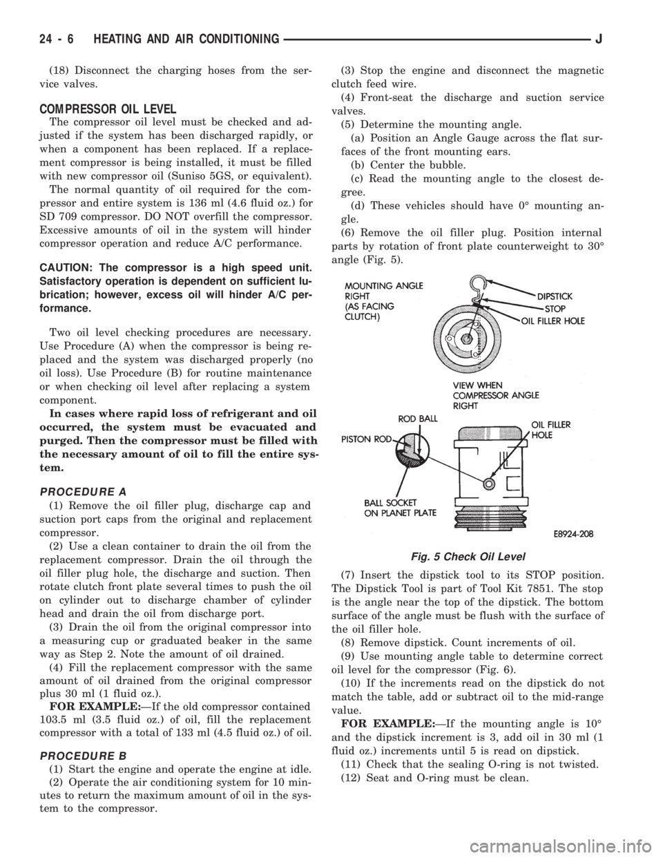
(6) Remove the oil filler plug. Position internal
parts by rotation of front plate counterweight to 30É
angle (Fig. 5).
(7) Insert the dipstick tool to its STOP position.
The Dipstick Tool is part of Tool Kit 7851. The stop
is the angle near the top of the dipstick. The bottom
surface of the angle must be flush with the surface of
the oil filler hole.
(8) Remove dipstick. Count increments of oil.
(9) Use mounting angle table to determine correct
oil level for the compressor (Fig. 6).
(10) If the increments read on the dipstick do not
match the table, add or subtract oil to the mid-range
value.
FOR EXAMPLE:ÐIf the mounting angle is 10É
and the dipstick increment is 3, add oil in 30 ml (1
fluid oz.) increments until 5 is read on dipstick.
(11) Check that the sealing O-ring is not twisted.
(12) Seat and O-ring must be clean.
Fig. 5 Check Oil Level
24 - 6 HEATING AND AIR CONDITIONINGJ
Page 1677 of 1784
SERVICE DIAGNOSISÐELECTRICAL
BLOWER CONTROLSÐXJ VEHICLES
DESCRIPTION
The blower motor delivers air to the inside of the
vehicle. Its speed is controlled by the blower switch
and the blower resistors. With the switch in LO, part
of the battery voltage is supplied to the motor
through all of the resistors. The motor runs slowly.
As the blower switch is moved to a higher speed, the
switch allows more voltage to be applied to the
blower motor, which will increase its speed. When
the switch is in HI, the blower resistors are bypassed
and battery voltage is applied directly to the blower
motor. The motor runs at the fastest speed in this
mode.
DIAGNOSIS
Refer to the Group 8W, Wiring Diagrams for com-
plete system schematic.
1. BLOWER MOTOR INOPERATIVE
²Remove and inspect fuse. If the fuse is blown, re-
place fuse.
2. BLOWER MOTOR INOPERATIVE (HI Posi-
tion)
Put the ignition switch in RUN, the select switch
in HEAT and the blower switch on HI.
²Blower motor connector (Terminal A) should be
battery voltage. If not go to next step.
²Blower motor connector (Terminal B) should be 0
ohms. If not, repair wire to ground.
²Blower switch connector (Terminal C) should be
battery voltage. If battery voltage replace blower
switch. If not, replace select switch.
3. BLOWER MOTOR INOPERATIVE (LO, M1
& M2 Positions)
Ignition switch in RUN, select switch in HEAT.
²Blower resistors connector (Terminal D) should be
battery voltage. If not, replace select switch.
²Blower resistors connector (Terminal C) should be
battery voltage. If not, replace blower switch.
²Blower resistors connector (Terminal A) should be
battery voltage. If not, replace blower switch.
²Blower resistors connector (Terminal B) should be
battery voltage. If not, replace blower resistor.
AIR CONDITIONING SYSTEMÐXJ VEHICLES
DESCRIPTION
The A/C Compressor Clutch is belt-driven by the
engine. A clutch, operated by a solenoid, automati-
cally turns the compressor on and off to control evap-
orator icing.
The A/C Compressor Clutch operation is controlled
by several components: the A/C Low-Pressure
Switch, Thermostat Switch, Fuel Pump Relay, A/C
Clutch Relay and the Engine Controller.The A/C low pressure switch opens when there is
not enough refrigerant in the system. When this hap-
pens, voltage is no longer present at the Engine Con-
troller. The Engine Controller will turn off the A/C
clutch relay. With the proper refrigerant level in the
system, the low pressure switch remains closed.
When the evaporator temperature is low enough to
ice the cooling coils, the thermostat switch opens.
The Engine Controller will turn off the A/C clutch.
The thermostat switch closes when the temperature
rises. The Engine Controller will then turn the A/C
clutch relay on again.
DIAGNOSIS
Refer to the Group 8W, Wiring Diagrams for com-
plete system schematic.
With engine running, Engine Controller may delay
A/C clutch up to 30 seconds.
1. A/C COMPRESSOR CLUTCH INOPERA-
TIVE
Clutch connector disconnected.
²Jumper fused test lead, battery to clutch connec-
tor, clutch should operate. If not, replace compressor
clutch assembly.
2. A/C LOW PRESSURE SWITCH
Ignition in RUN, A/C controls in MAX or NORM.
²Low pressure switch connector (Terminal A)
should be battery voltage. If not, repair open to select
switch.
²Low pressure switch connector (Terminal C)
should be battery voltage. If not, check switch resis-
tance and check freon pressure.
3. A/C CLUTCH RELAY
Engine RUNNING, A/C controls in MAX or
NORM.
²Relay connector Pin 4 to ground should be battery
voltage. If not, check fuse F6 in Power Distribution
Center.
²Ground A/C clutch relay (Terminal 5) should have
A/C compressor clutch engagement. If not, check En-
gine Controller Terminals 27, 28 and 34.
HEATING SYSTEMÐYJ VEHICLES
DESCRIPTION
The blower motor circuit begins at a 25 amp fuse
that receives its battery feed from the ignition
switch. From the fuse the circuit extends to a micro-
switch mounted on the heater control.
The micro-switch is normally closed is operated by
a cam on the heater control lever. In all heater con-
trol lever positions, except OFF and VENT, the
blower motor electrical circuit is complete. In the
OFF and VENT positions the cam depresses the mi-
cro-switch lever opening the electrical circuit to the
blower motor.
24 - 14 HEATING AND AIR CONDITIONINGJ
Page 1678 of 1784
The blower switch allows the driver to select 1 of 3
blower speedsÐlow, medium and high. In the high
speed position, the switch connects the motor directly
to the battery source. The remaining 2 slower speeds
are accomplished by routing the battery source
through a resistor assembly.
The resistor and switch are wired in such a way
that only a single wire is needed to operate the
blower motor at 3 different speeds.
DIAGNOSIS
Refer to Group 8W, Wiring Diagrams for complete
system schematic.
1. HEAT/OFF MICRO-SWITCH
Place selector lever in heat mode and turn ignition
switch to RUN.
²Heat/Off micro-switch connector supply side should
be battery voltage. If not, repair open from fuse
No.12.
²Heat/Off micro-switch connector output side should
be battery voltage. If not, replace Heat/Off micro-
switch.
2. BLOWER SWITCH
Turn ignition switch to RUN and place selector le-
ver in HEAT mode.
²Blower switch (terminal A) should be battery volt-
age. If not, repair open from HEAT/OFF switch con-
nector output side to blower switch.
²Blower switch (terminal D) with blower switch in
HI should be battery voltage. If not, replace blower
switch.
²Blower switch (terminal C) with blower switch in
LO should be battery voltage. If not, replace blower
switch.
²Blower switch (terminal B) with blower switch in
MED should be battery voltage. If not replace blower
switch.
3. BLOWER RESISTOR
Turn ignition switch to RUN for voltage tests and
turn ignition switch to OFF for resistance tests.
²Blower resistor (Terminal A) with blower switch in
LO should be battery voltage. If not, repair open be-
tween blower switch and blower resistor.
²Blower resistor (Terminal C) with blower switch in
MED should be battery voltage. If not, repair open
between blower switch and blower resistor.
²Blower resistor (Terminal B) with blower switch in
HI should be battery voltage. If not, repair open be-
tween blower switch and blower resistor.
²Blower resistor between Terminals A and B should
be 3.25 ohms, if not replace blower resistor.
²Blower resistor between Terminals B and C should
be 0.60 ohms. If not, replace blower resistor.
²Blower resistor between terminals A and C should
be 2.65 ohms, if not replace blower resistor.4. BLOWER MOTOR
Turn blower motor switch to HI and place selector
lever in HEAT mode. Turn ignition switch to RUN
for voltage tests or to OFF for resistance tests.
²Blower motor voltage should be battery voltage. If
not, repair open from blower switch.
²Blower motor case to clean chassis ground should
be 0 ohms. If not, repair/replace blower motor.
AIR CONDITIONING SYSTEMÐYJ VEHICLES
DESCRIPTION
The air conditioning circuit consists of 3 segments;
battery supply, blower motor and compressor clutch.
The 3 segments have a common connection point at
the blower switch.
The power supply segment of the circuit extends
from the 25 amp HTR/FAN fuse to the blower
switch. From the blower switch, battery feed is
routed to the blower motor and compressor clutch
segments of the circuit.
The blower motor segment consists of the 3 wires
from the blower switch to the motor, the motor itself
and the motor ground wire. Through the switch, the
3 wires connect the motor brushes to battery supply.
When connected to battery feed, the separate brushes
provide the 3 blower speedsÐLO, MED, and HIGH.
In all blower switch positions except OFF, the com-
pressor clutch segment of the circuit also receives
battery feed. ON and OFF cycling of the compressor
and therefore the temperature of the outlet air is
regulated by the thermostatic control. A thermal sen-
sor extends from the control to the evaporator hous-
ing. When the temperature of the evaporator drops
below the set temperature, the thermostatic control
opens the clutch circuit. The circuit remains open un-
til evaporator temperature rises above the set tem-
perature.
The compressor clutch segment of the circuit also
contains a low pressure switch. If the pressure in the
refrigerant system drops due to a leak, the circuit is
opened to prevent damage to the compressor.
The last component in the compressor clutch seg-
ment of the circuit is the clutch coil. When the coil is
connected to battery feed, its windings form an elec-
tromagnet that pulls the clutch hub against the
clutch pulley.
DIAGNOSIS
BLOWER MOTOR
Refer to Group 8W, Wiring Diagrams for complete
system schematic.
1. FUSEÐIgnition in RUN.
²Heater blower motor operates. If not, check fuse
No.12.
JHEATING AND AIR CONDITIONING 24 - 15
Page 1679 of 1784
²Battery side of fuse No.12 should be battery volt-
age. If not, repair open from ignition switch.
²A/C blower switch (terminal A) should be battery
voltage. If not, repair open from fuse No.12.
2. BLOWER SWITCHÐIgnition in RUN.
²A/C blower switch (Terminal A) with blower
switch in any position should be battery voltage. If
not, repair open from fuse panel.
²A/C blower switch (Terminal L) with blower
switch in LO should be battery voltage. If not, re-
place switch.
²A/C blower switch (Terminal M) with blower
switch in MED should be battery voltage. If not, re-
place switch.
²A/C blower switch (Terminal H) with blower
switch in HI should be battery voltage. If not, replace
switch.
3. BLOWER MOTOR
Turn ignition switch to RUN for voltage tests and
turn ignition switch to OFF for resistance tests.
²A/C blower housing to ground (Terminal G) should
be 0 ohms. If not, repair ground connection. If the
blower motor is still inoperative, replace motor.
²A/C blower motor connector (Terminal C) with
blower switch in LO should be battery voltage. If not,
repair open from blower switch. If the blower motor
is still inoperative, replace motor.
²A/C blower motor connector (Terminal B) with
blower switch in MED should be battery voltage. If
not, repair open from blower switch. If the blower
motor is still inoperative, replace motor.
²A/C blower motor connector (Terminal A) with
blower switch in HI should be battery voltage. If not,
repair open from blower switch. If the blower motor
is still inoperative, replace motor.COMPRESSOR CLUTCH
Refer to Group 8W, Wiring Diagrams for complete
system schematic.
With engine running, Engine Controller may delay
A/C clutch up to 30 seconds.
1. COMPRESSOR CLUTCH.
²Jumper wire from battery positive post to A/C
compressor clutch connector (Terminal A), clutch
should engage. If not, go to next step with jumper in-
stalled.
²Jumper wire from clutch coil frame to chassis
ground, clutch should engage. If not, repair clutch
coil ground or replace coil.
2. LOW PRESSURE SWITCH
Turn ignition switch to RUN, A/C blower switch to
ON and thermostatic control set to MAX cool.
²A/C low pressure switch connector (Terminal A)
should be battery voltage. If not, proceed to thermo-
static control tests (Step 3).
²Jumper wire across A/C low pressure switch con-
nector (Terminals A and B), clutch should engage. If
not, check system refrigerant charge. If system is
properly charged, replace A/C low pressure switch.
3. THERMOSTATIC CONTROL
Turn ignition switch to RUN, A/C blower switch to
ON and thermostatic control set to MAX cool.
²Thermostatic control connector (Terminal A)
should be battery voltage. If not, repair open from
blower switch.
²Thermostatic control connector (Terminal B)
should be battery voltage. If not, replace thermo-
static control.
²A/C low pressure switch connector (Terminal A)
should be battery voltage. If not, repair open from
thermostatic control.
24 - 16 HEATING AND AIR CONDITIONINGJ
Page 1680 of 1784
COMPRESSOR OVERHAUL
INDEX
page page
Compressor............................. 17
Compressor Isolation...................... 17
Description............................. 17Magnetic Clutch......................... 18
Purging Compressor of Air................. 17
DESCRIPTION
The A/C system uses a Sanden compressor. This
compressor is a 7 piston design. Designated the SD-
709, the compressor is mounted on the front right
side of the engine and is driven by a serpentine belt.
System lubrication is provided by 135cc615cc (4.6
cu. in.60.5 cu. in.) of 500 viscosity refrigerant oil.
The clutch used on the compressor consists of 3 ba-
sic components: the pulley, front plate and the field
coil. The pulley and field coil are attached to the
front head of the compressor with tapered snap rings.
The hub is keyed to the compressor shaft and is re-
tained on the shaft with a self-locking nut. Special
service tools are required to remove and install the
clutch plate on the compressor shaft.
COMPRESSOR ISOLATION
It is not necessary to discharge the system for com-
pressor removal. The compressor can be isolated from
the remainder of the system and eliminate the need
for recharging when performing compressor service.
(1) Connect pressure gauge and manifold.
(2) Close both gauge hand valves.
(3) Mid-position both service valves.
WARNING: USE EXTREME CAUTION WHEN THE
ENGINE IS OPERATING. DO NOT STAND IN A DI-
RECT LINE WITH THE FAN. DO NOT PUT YOUR
HANDS NEAR THE PULLEYS, BELTS OR FAN. DO
NOT WEAR LOOSE CLOTHING.
(4) Start the engine and operate the air condition-
ing system.
(5) Turn the suction service valve slowly clockwise
toward the front seated position.
(6) When pressure drops to zero, stop the engine
and compressor and quickly finish front-seating the
suction service valve.
(7) Front-seat the discharge service valve.
(8) Loosen the oil level check plug slowly to re-
lease any internal pressure in the compressor.
The compressor is now isolated from the remainder
of the system.
The service valves can be removed from the com-
pressor.
PURGING COMPRESSOR OF AIR
The compressor must be purged of air whenever it
has been isolated for an oil level check or other ser-
vice procedures without discharging the entire sys-
tem.
(1) Cap the service gauge ports on both of the ser-
vice valves.
(2) Back-seat the suction service valve to allow the
system refrigerant to enter the compressor.
(3) Place the discharge service valve in the mid-po-
sition or cracked-position.
(4) Loosen the discharge service valve gauge port
cap to permit the refrigerant to force any air out of
the compressor.
(5) Back-seat the discharge service valve and
tighten the gauge port cap.
(6) The compressor is now ready for service.
COMPRESSOR
REMOVAL
(1) Isolate the compressor.
(2) Disconnect negative cable from battery.
(3) Disconnect the clutch lead wire.
(4) Remove the discharge and inlet (suction) ser-
vice valves from the compressor. Plug or tape all the
openings.
(5) Remove the serpentine drive belt (refer to
Group 7, Cooling System for the proper procedure).
(6) Remove the bolts and lift the compressor from
the mounting bracket (Figs. 1 and 2).
INSTALLATION
If a replacement compressor is being installed;
check the oil level. Add or subtract oil as neces-
sary and install the magnetic clutch on the com-
pressor.
(1) If the mounting bracket was removed, install
the bracket to the block. Tighten the mounting bolts
to 27 NIm (20 ft. lbs.) torque.
(2) Install the compressor on the mounting
bracket. Tighten the bolts to 27 NIm (20 ft. lbs.)
torque.
(3) Install the serpentine drive belt (refer to Group
7, Cooling System for the proper procedure).
(4) Tighten the serpentine drive belt to the speci-
fied tension.
²New belt tensionÐ800-900 N (180-200 lb-f).
JHEATING AND AIR CONDITIONING 24 - 17