1994 JEEP CHEROKEE check oil
[x] Cancel search: check oilPage 1114 of 1784
A correct lubricant level check can only be made
when the vehicle is level; use a drive-on hoist to en-
sure this. Also allow the lubricant to settle for a
minute or so before checking. These recommenda-
tions will ensure an accurate check and avoid an un-
der-or-overfill condition.
HARD SHIFTING
Hard shifting is usually caused by a low lubricant
level, improper or contaminated lubricants, compo-
nent damage, incorrect clutch adjustment, or by a
damaged clutch pressure plate or disc.
Substantial lubricant leaks can result in gear, shift
rail, synchro and bearing damage. If a leak goes un-
detected for an extended period, the first indications
of a problem are usually hard shifting and noise.
Incorrect or contaminated lubricants can also con-
tribute to hard shifting. The consequence of using
non-recommended lubricants is noise, excessive wear,
internal bind and hard shifting.
Improper clutch release is a frequent cause of hard
shifting. Incorrect adjustment or a worn, damaged
pressure plate or disc can cause incorrect release. If
the clutch problem is advanced, gear clash during
shifts can result.
Worn or damaged synchro rings can cause gear
clash when shifting into any forward gear. In some
new or rebuilt transmissions, new synchro rings maytend to stick slightly causing hard or noisy shifts. In
most cases, this condition will decline as the rings
wear-in.
TRANSMISSION NOISE
Most manual transmissions make some noise dur-
ing normal operation. Rotating gears can generate a
mild whine that may only be audible at extreme
speeds.
Severe, obviously audible transmission noise is
generally the result of a lubricant problem. Insuffi-
cient, improper, or contaminated lubricant can pro-
mote rapid wear of gears, synchros, shift rails, forks
and bearings. The overheating caused by a lubricant
problem, can also lead to gear breakage.
TRANSMISSION REMOVAL
(1) Shift transmission into first or third gear. Then
raise vehicle on hoist.
(2) Support engine with adjustable jack stand. Be
sure to position wood block between jack and oil pan.
(3) Disconnect necessary exhaust system compo-
nents.
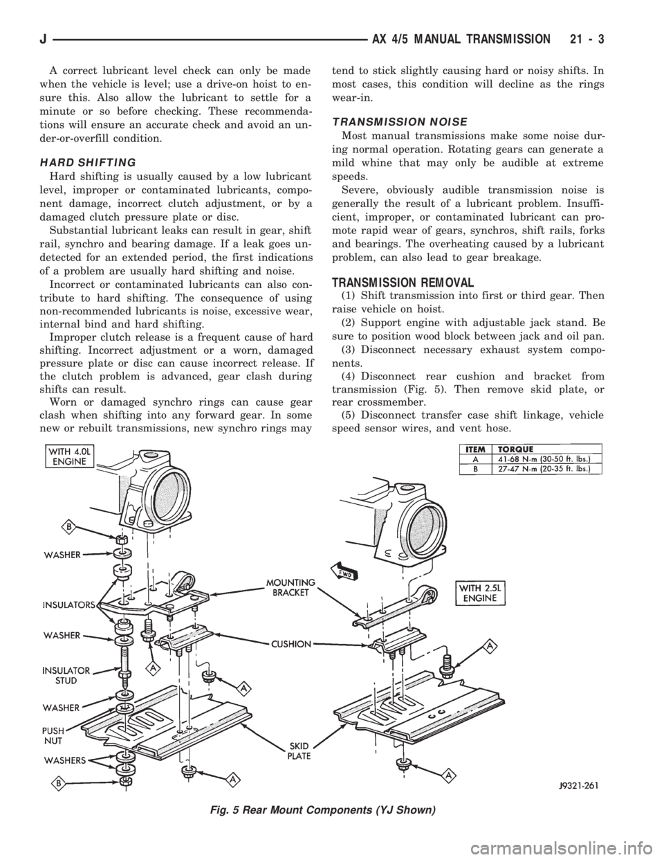
(4) Disconnect rear cushion and bracket from
transmission (Fig. 5). Then remove skid plate, or
rear crossmember.
(5) Disconnect transfer case shift linkage, vehicle
speed sensor wires, and vent hose.
Fig. 5 Rear Mount Components (YJ Shown)
JAX 4/5 MANUAL TRANSMISSION 21 - 3
Page 1125 of 1784
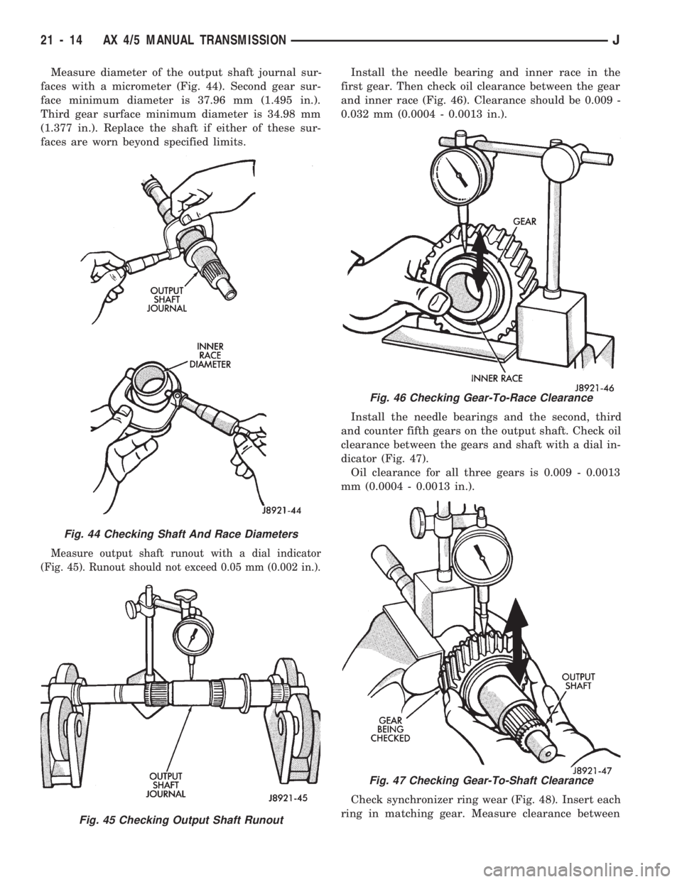
Measure diameter of the output shaft journal sur-
faces with a micrometer (Fig. 44). Second gear sur-
face minimum diameter is 37.96 mm (1.495 in.).
Third gear surface minimum diameter is 34.98 mm
(1.377 in.). Replace the shaft if either of these sur-
faces are worn beyond specified limits.
Measure output shaft runout with a dial indicator
(Fig. 45). Runout should not exceed 0.05 mm (0.002 in.).
Install the needle bearing and inner race in the
first gear. Then check oil clearance between the gear
and inner race (Fig. 46). Clearance should be 0.009 -
0.032 mm (0.0004 - 0.0013 in.).
Install the needle bearings and the second, third
and counter fifth gears on the output shaft. Check oil
clearance between the gears and shaft with a dial in-
dicator (Fig. 47).
Oil clearance for all three gears is 0.009 - 0.0013
mm (0.0004 - 0.0013 in.).
Check synchronizer ring wear (Fig. 48). Insert each
ring in matching gear. Measure clearance between
Fig. 44 Checking Shaft And Race Diameters
Fig. 45 Checking Output Shaft Runout
Fig. 46 Checking Gear-To-Race Clearance
Fig. 47 Checking Gear-To-Shaft Clearance
21 - 14 AX 4/5 MANUAL TRANSMISSIONJ
Page 1132 of 1784
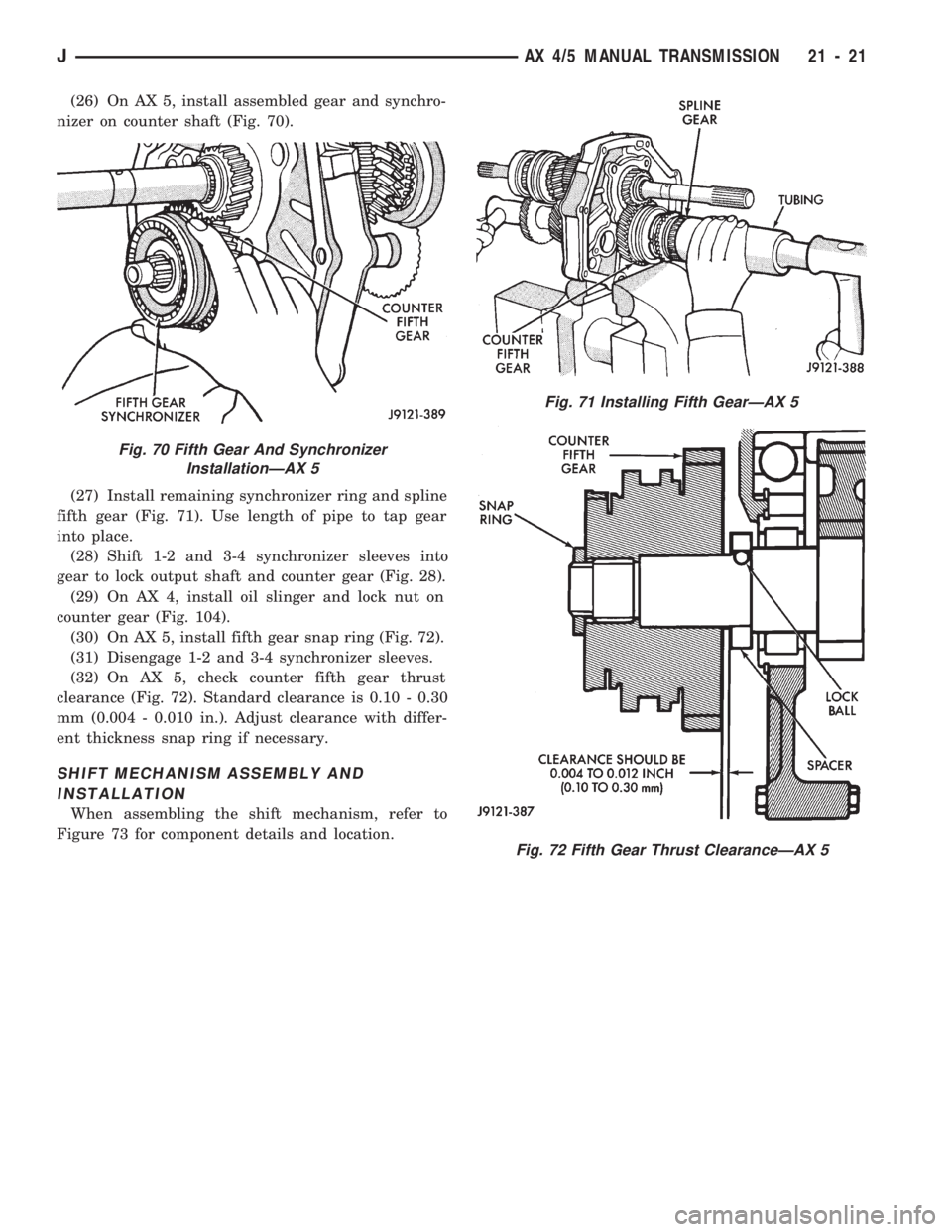
(26) On AX 5, install assembled gear and synchro-
nizer on counter shaft (Fig. 70).
(27) Install remaining synchronizer ring and spline
fifth gear (Fig. 71). Use length of pipe to tap gear
into place.
(28) Shift 1-2 and 3-4 synchronizer sleeves into
gear to lock output shaft and counter gear (Fig. 28).
(29) On AX 4, install oil slinger and lock nut on
counter gear (Fig. 104).
(30) On AX 5, install fifth gear snap ring (Fig. 72).
(31) Disengage 1-2 and 3-4 synchronizer sleeves.
(32) On AX 5, check counter fifth gear thrust
clearance (Fig. 72). Standard clearance is 0.10 - 0.30
mm (0.004 - 0.010 in.). Adjust clearance with differ-
ent thickness snap ring if necessary.
SHIFT MECHANISM ASSEMBLY AND
INSTALLATION
When assembling the shift mechanism, refer to
Figure 73 for component details and location.
Fig. 70 Fifth Gear And Synchronizer
InstallationÐAX 5
Fig. 71 Installing Fifth GearÐAX 5
Fig. 72 Fifth Gear Thrust ClearanceÐAX 5
JAX 4/5 MANUAL TRANSMISSION 21 - 21
Page 1144 of 1784
TRANSMISSION SHIFT PATTERN
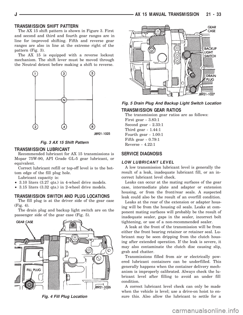
The AX 15 shift pattern is shown in Figure 3. First
and second and third and fourth gear ranges are in
line for improved shifting. Fifth and reverse gear
ranges are also in line at the extreme right of the
pattern (Fig. 3).
The AX 15 is equipped with a reverse lockout
mechanism. The shift lever must be moved through
the Neutral detent before making a shift to reverse.
TRANSMISSION LUBRICANT
Recommended lubricant for AX 15 transmissions is
Mopar 75W-90, API Grade GL-5 gear lubricant, or
equivalent.
Correct lubricant refill or top-off level is to the bot-
tom edge of the fill plug hole.
Lubricant capacity is:
²3.10 liters (3.27 qts.) in 4-wheel drive models.
²3.15 liters (3.32 qts.) in 2-wheel drive models.
TRANSMISSION SWITCH AND PLUG LOCATIONS
The fill plug is at the driver side of the gear case
(Fig. 4).
The drain plug and backup light switch are on the
passenger side of the gear case (Fig. 5).
TRANSMISSION GEAR RATIOS
The transmission gear ratios are as follows:
First gear - 3.83:1
Second gear - 2.33:1
Third gear - 1.44:1
Fourth gear - 1.00:1
Fifth gear - 0.79:1
Reverse - 4.22:1
SERVICE DIAGNOSIS
LOW LUBRICANT LEVEL
A low transmission lubricant level is generally the
result of a leak, inadequate lubricant fill, or an in-
correct lubricant level check.
Leaks can occur at the mating surfaces of the gear
case, intermediate plate and adapter or extension
housing, or from the front/rear seals. A suspected
leak could also be the result of an overfill condition.
Leaks at the rear of the extension or adapter hous-
ing will be from the housing oil seals. Leaks at com-
ponent mating surfaces will probably be the result of
inadequate sealer, gaps in the sealer, incorrect bolt
tightening, or use of a non-recommended sealer.
A leak at the front of the transmission will be from
either the front bearing retainer or retainer seal. Lu-
bricant may be seen dripping from the clutch hous-
ing after extended operation. If the leak is severe, it
may also contaminate the clutch disc causing slip,
grab and chatter.
Transmissions filled from air or electrically pow-
ered lubricant containers can be underfilled. This
generally happens when the container delivery mech-
anism is improperly calibrated. Always check the lu-
bricant level after filling to avoid an under fill
condition.
A correct lubricant level check can only be made
when the vehicle is level; use a drive-on hoist to en-
sure this. Also allow the lubricant to settle for a
Fig. 3 AX 15 Shift Pattern
Fig. 4 Fill Plug Location
Fig. 5 Drain Plug And Backup Light Switch Location
JAX 15 MANUAL TRANSMISSION 21 - 33
Page 1180 of 1784
30RH/32RH TRANSMISSION DIAGNOSIS
INDEX
page page
Air Pressure Test........................ 73
Analyzing the Road Test................... 70
Converter Housing Leak Diagnosis........... 73
Converter Stall Test...................... 72
Diagnosis Guides and Charts............... 76
Fluid Level and Condition.................. 69Gearshift Linkage........................ 70
General Information....................... 69
Hydraulic Pressure Test................... 71
Preliminary Diagnosis..................... 69
Road Test.............................. 70
Transmission Throttle Valve Cable Adjustment . . 70
GENERAL INFORMATION
Automatic transmission problems are generally the
result of:
²poor engine performance
²incorrect fluid level
²incorrect cable/linkage adjustment
²incorrect band adjustment
²incorrect hydraulic control pressure adjustments
²hydraulic component malfunctions
²mechanical component malfunctions.
Begin diagnosis by checking the easily accessible
items such as fluid level, fluid condition and control
linkage adjustment. A road test will determine if fur-
ther diagnosis is necessary.
Procedures outlined in this section should be per-
formed in the following sequence to realize the most
accurate results:
²Preliminary diagnosis
²Check fluid Level and condition
²Check control linkage Adjustment
²Road test
²Stall test
²Hydraulic pressure test
²Air pressure tests
²Leak Tests
²Analyze test results and consult diagnosis charts
PRELIMINARY DIAGNOSIS
Two basic procedures are required. One procedure
for vehicles that are driveable and an alternate pro-
cedure for disabled vehicles (will not back up or
move forward).
Vehicle Is Driveable
(1) Check fluid level and condition.
(2) Adjust throttle cable and gearshift linkage if
complaint was based on delayed, erratic, or harsh
shifts.
(3) Road test vehicle and note transmission operat-
ing characteristics.
(4) Perform stall test if complaint is based on slug-
gish, low speed acceleration or abnormal throttle
opening needed to maintain normal speeds with
properly tuned engine.
(5) Perform hydraulic pressure tests.(6) Perform air pressure test to check clutch-band
operation.
Vehicle Is Disabled
(1) Check fluid level and condition.
(2) Check for broken, disconnected throttle link-
age.
(3) Check for cracked, leaking cooler lines, or
loose, missing pressure port plugs.
(4) Raise vehicle, start engine, shift transmission
into gear and note following:
(a) If propeller shafts turn but wheels do not,
problem is with differential or axle shafts.
(b) If propeller shafts do not turn and transmis-
sion is noisy, stop engine. Remove oil pan, and
check for debris. If pan is clear, remove transmis-
sion and check for damaged drive plate, converter,
oil pump or input shaft.
(c) If propeller shafts do not turn and transmis-
sion is not noisy, perform hydraulic pressure test to
determine if problem is a hydraulic or mechanical.
FLUID LEVEL AND CONDITION
(1) Position vehicle on level surface. This is impor-
tant in obtaining an accurate fluid level check.
(2) To avoid false readings, which could produce
under or over fill condition, do not check level until
fluid is at normal operating temperature.
(3) Shift transmission into Neutral.
(4) Apply parking brakes.
(5) Operate engine at curb idle speed.
WARNING: WHEN PERFORMING UNDERHOOD OP-
ERATIONS WITH THE ENGINE RUNNING, KEEP
YOUR HANDS WELL AWAY FROM HOT OR ROTAT-
ING ENGINE COMPONENTS. DO NOT WEAR
LOOSE ARTICLES OF CLOTHING WHICH COULD
BECOME ENTANGLED IN ENGINE COMPONENTS
OR ACCESSORIES.
(6) Clean dipstick filler cap and tube before remov-
ing dipstick.
(7) Remove dipstick and inspect fluid level.
²Correct level is to FULL mark
²Acceptable level is between ADD and FULL marks
J30RH/32RH TRANSMISSION DIAGNOSIS 21 - 69
Page 1184 of 1784
STALL TEST PROCEDURE
(1) Connect tachometer to engine.
(2) Check and adjust transmission fluid level.
(3) Start and run engine until transmission fluid
reaches normal operating temperature.
(4) Block front wheels.
(5) Fully apply service and parking brakes.
(6) Open throttle completely for no more than five
seconds and record maximum engine rpm registered
on tachometer.
CAUTION: Stall testing causes a rapid increase in
transmission fluid temperature. Do not hold the
throttle open any longer than five seconds. If more
than one stall test is required, run the engine at
1000 rpm with the transmission in Neutral for at
least 20 seconds to cool the fluid.
(7) If engine speed exceeds maximum shown in
stall speed chart, release accelerator immediately.
This indicates that transmission clutch slippage is
occurring.
(8) Shift transmission into Neutral. Run engine for
20 seconds to cool fluid. Then stop engine, shift
transmission into Park and release brakes.
(9) Stall speeds should be in 1700-2000 rpm range.
(10) Refer to Stall Test Diagnosis.
STALL TEST DIAGNOSIS
Stall Speed Too High
If the stall speed exceeds specifications by more
than 200 rpm, transmission clutch slippage is indi-
cated.
Stall Speed Too Low
Low stall speeds with a properly tuned engine in-
dicate a torque converter overrunning clutch prob-
lem. The condition should be confirmed by road
testing prior to converter replacement.
The converter overrunning clutch is slipping when
stall speeds are 250 to 350 rpm below specified min-
imum. And when the vehicle operates properly at
highway speeds but has poor low speed acceleration.
Stall Speed Normal
If stall speeds are normal but abnormal throttle
opening is required to maintain highway speeds, the
converter overrunning clutch is seized and the torque
converter must be replaced.
Converter Noise During Test
A whining noise caused by fluid flow is normal
during a stall test. However, loud metallic noises in-
dicate a damaged converter. To confirm that noise is
originating from the converter, operate the vehicle at
light throttle in Drive and Neutral on a hoist and lis-
ten for noise coming from the converter housing.
AIR PRESSURE TEST
Air pressure testing can be used to check clutch
and band operation with the transmission either in
the vehicle, or on the work bench as a final check af-
ter overhaul.
Air pressure testing requires that the oil pan and
valve body be removed from the transmission.
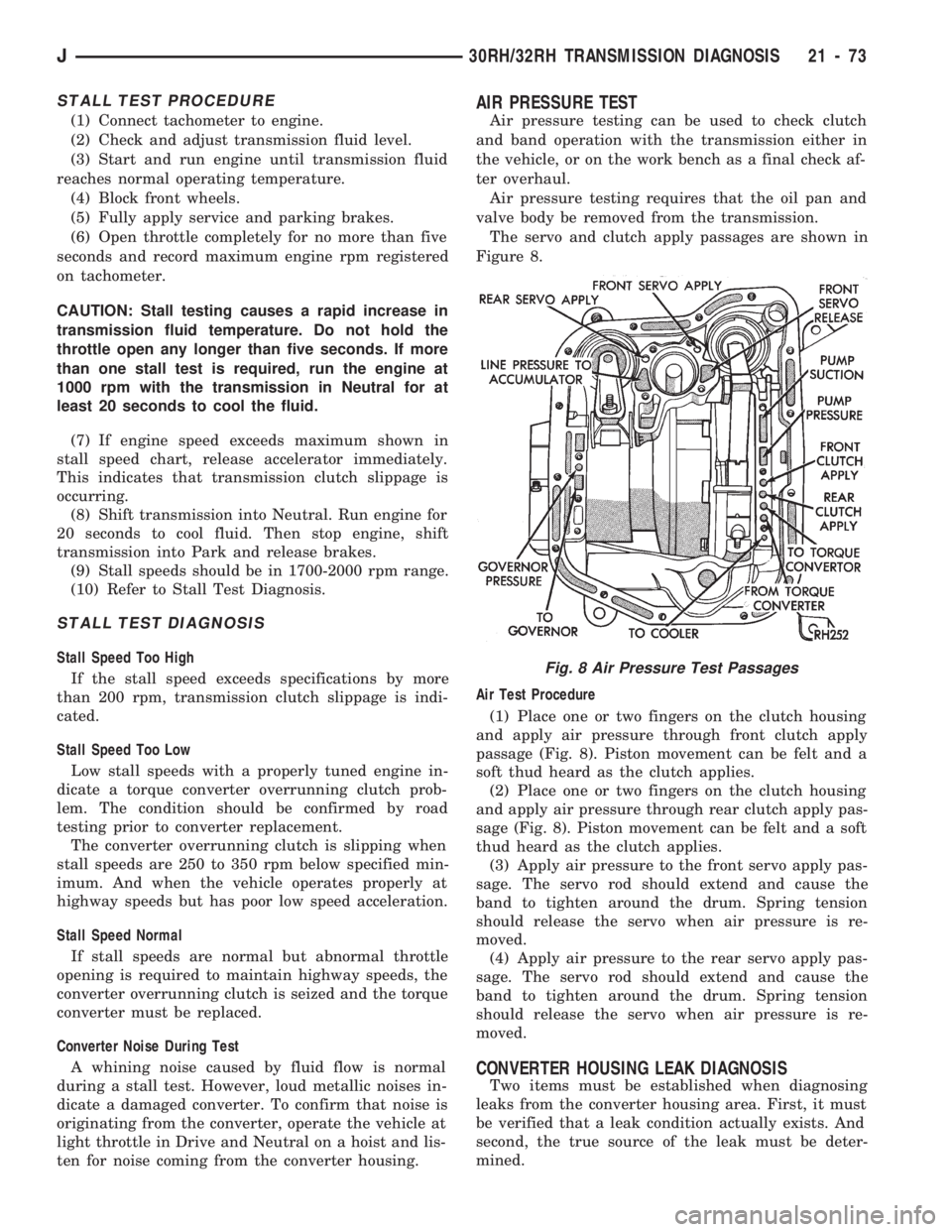
The servo and clutch apply passages are shown in
Figure 8.
Air Test Procedure
(1) Place one or two fingers on the clutch housing
and apply air pressure through front clutch apply
passage (Fig. 8). Piston movement can be felt and a
soft thud heard as the clutch applies.
(2) Place one or two fingers on the clutch housing
and apply air pressure through rear clutch apply pas-
sage (Fig. 8). Piston movement can be felt and a soft
thud heard as the clutch applies.
(3) Apply air pressure to the front servo apply pas-
sage. The servo rod should extend and cause the
band to tighten around the drum. Spring tension
should release the servo when air pressure is re-
moved.
(4) Apply air pressure to the rear servo apply pas-
sage. The servo rod should extend and cause the
band to tighten around the drum. Spring tension
should release the servo when air pressure is re-
moved.
CONVERTER HOUSING LEAK DIAGNOSIS
Two items must be established when diagnosing
leaks from the converter housing area. First, it must
be verified that a leak condition actually exists. And
second, the true source of the leak must be deter-
mined.
Fig. 8 Air Pressure Test Passages
J30RH/32RH TRANSMISSION DIAGNOSIS 21 - 73
Page 1185 of 1784
Some suspected converter housing fluid leaks may
not be leaks at all. Residual fluid in the housing, or
excess fluid spilled during factory fill or refill after
repair can be mistaken for a leak. In addition, a rear
main seal leak can also be mistaken for a pump seal
leak if care is exercised.
Converter housing leaks have several potential
sources. Through careful observation, a leak source
can be identified before removing the transmission
for repair.
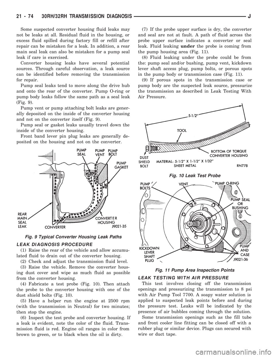
Pump seal leaks tend to move along the drive hub
and onto the rear of the converter. Pump O-ring or
pump body leaks follow the same path as a seal leak
(Fig. 9).
Pump vent or pump attaching bolt leaks are gener-
ally deposited on the inside of the converter housing
and not on the converter itself (Fig. 9).
Pump seal or gasket leaks usually travel down the
inside of the converter housing.
Front band lever pin plug leaks are generally de-
posited on the housing and not on the converter.
LEAK DIAGNOSIS PROCEDURE
(1) Raise the rear of the vehicle and allow accumu-
lated fluid to drain out of the converter housing.
(2) Check and adjust the transmission fluid level.
(3) Raise the vehicle. Remove the converter hous-
ing dust cover and wipe as much fluid as possible
from the converter housing.
(4) Fabricate a test probe (Fig. 10). Then attach
the probe to the converter housing with one of the
dust shield bolts (Fig. 10).
(5) Have a helper run the engine at 2500 rpm
(with the transmission in Neutral) for two minutes;
then stop the engine.
(6) Inspect the test probe and converter housing. If
a leak is evident, note the color of the fluid. Trans-
mission fluid is red. Engine oil ranges in color from
brown to green, or to black when the oil is dirty.(7) If the probe upper surface is dry, the converter
and seal are not at fault. A path of fluid across the
probe upper surface indicates a converter or seal
leak. Fluid leakingunderthe probe is coming from
the pump housing area (Fig. 11).
(8) Fluid leaking under the probe could be from
the: pump seal and/or bushing, pump vent, kickdown
lever shaft access plug, pump bolts, or porous spots
in the pump body or transmission case (Fig. 11).
(9) If porous spots in the transmission case or
pump body are the suspected leak source, pressurize
the transmission as described in Leak Testing With
Air Pressure.
LEAK TESTING WITH AIR PRESSURE
This test involves closing off the transmission
openings and pressurizing the transmission to 8 psi
with Air Pump Tool 7700. A soapy water solution is
applied to suspected leak points before and during
the pressure test. Leaks will be indicated by the
presence of air bubbles coming through the solution.
Some transmission openings such as the fill tube
and front cooler line fitting can be closed off with a
rubber plug or similar device. Plugs can secured with
wire or duct tape.
Fig. 9 Typical Converter Housing Leak Paths
Fig. 10 Leak Test Probe
Fig. 11 Pump Area Inspection Points
21 - 74 30RH/32RH TRANSMISSION DIAGNOSISJ
Page 1207 of 1784
30RH/32RH IN-VEHICLE SERVICE
INDEX
page page
Checking Fluid Level and Condition........... 96
Front Band Adjustment.................... 99
Gearshift Linkage Adjustment (YJ)............ 96
Governor and Park Gear Service............ 101
Oil Filter Replacement.................... 100
Park Interlock Cable Adjustment (XJ)......... 97
Park Lock Component Replacement......... 102
Park/Neutral Position Switch Service......... 103
Rear Band Adjustment.................... 99
Recommended Fluid...................... 96
Servicing Transmission Cooler Lines and Fittings. 106
Shift Cable Adjustment (XJ)................ 97
Speedometer Service.................... 103
Transmission Cooler Flow Testing........... 106
Transmission Cooler Reverse Flushing....... 105
Transmission Throttle Cable Adjustment (XJ/YJ) . 98
Valve Body Installation................... 101
Valve Body Removal..................... 100
Valve Body Service...................... 100
RECOMMENDED FLUID
The recommended and preferred fluid for 30RH/
32RH transmissions is Mopar ATF Plus, Type 7176.
Mopar Dexron II is acceptable but should only be
used when ATF Plus is not available.
Transmission fluid capacity is approximately 17
pints (7.9 liters). This is the approximate amount of
fluid required to fill the transmission and torque con-
verter after overhaul.
CHECKING FLUID LEVEL AND CONDITION
(1) Position vehicle on flat, level surface. This is
important in obtaining an accurate fluid level check.
(2) To avoid false readings, which could produce
under or over fill condition, do not check level until
fluid is at normal operating temperature.
(3) Shift transmission into Neutral.
(4) Apply parking brakes.
(5) Operate engine at curb idle speed.
WARNING: WHEN PERFORMING UNDERHOOD OP-
ERATIONS WITH THE ENGINE RUNNING, KEEP
YOUR HANDS WELL AWAY FROM HOT OR ROTAT-
ING ENGINE COMPONENTS. DO NOT WEAR
LOOSE ARTICLES OF CLOTHING WHICH COULD
BECOME ENTANGLED IN ENGINE COMPONENTS
OR ACCESSORIES.
(6) Shift transmission through all gear ranges and
back to Neutral (leave engine running).
(7) Clean exterior of dipstick cap and fill tube be-
fore removing transmission dipstick.
(8) Remove dipstick and inspect fluid level.
²Correct level is to FULL mark
²Acceptable level is between ADD and FULL marks
(9) Check fluid condition. Fluid should be dark to
light red in color and free of dirt or debris.
(10) If fluid is discolored or smells burned but
transmission operation was OK, check cooler flow,
flush cooler and lines and change fluid and filter.
Then road test again to confirm proper operation.(11) If fluid is black or dark brown, burned/turned
to sludge, contains large quantities of metal or fric-
tion material particles, transmission will need over-
haul. Especially if problems were evident during
road test and preliminary diagnosis. Fluid cooler
should also be flow tested and flushed if necessary.
GEARSHIFT LINKAGE ADJUSTMENT (YJ)
(1) Check linkage adjustment by starting engine in
Park and Neutral.
(2) Adjustment is OK if engine starts only in park
and Neutral. Adjustment is incorrect if engine starts
in one but not both positions.
(3) If engine starts in any position other than Park
or Neutral, or if engine will not start at all, park/
neutral position switch may be faulty.
(4) Shift transmission into Park.
(5) Raise vehicle.
(6) Check condition of shift rods, bellcrank, bell-
crank brackets and linkage bushings/grommets (Fig.
1). Tighten, repair, replace worn, damaged parts. Do
not attempt adjustment if linkage components are
worn or damaged.
(7) Loosen shift rod trunnion lock bolt or nut. Be
sure upper shift rod slides freely in trunnion (Fig. 1).
Also be sure shift rods and bellcrank rotate freely
and do not bind at any point.
(8) Verify that manual lever is in Park detent
(Fig. 1). Move lever all the way rearward to be sure
it is in Park.
(9) Check for positive engagement of park lock by
attempting to rotate propeller shaft. Shaft will not
turn when park pawl is engaged.
(10) Adjust shift rod trunnion to a obtain free pin
fit in bellcrank arm and tighten trunnion lock bolt or
nut. Prevent shift rod from turning while tightening
bolt or nut. Gearshift linkage lash must be elimi-
nated to obtain proper adjustment. Eliminate lash by
pulling downward on shift rod and pressing upward
on bellcrank.
21 - 96 30RH/32RH IN-VEHICLE SERVICEJ