1994 JEEP CHEROKEE front
[x] Cancel search: frontPage 194 of 1784
ABS COMPONENT SERVICE
INDEX
page page
Acceleration Sensor Installation.............. 52
Acceleration Sensor Removal............... 52
Combination Valve ReplacementÐXJ......... 55
Combination Valve ReplacementÐYJ......... 55
Component Serviceability................... 47
Correct Fluid Level....................... 48
ECU ReplacementÐXJ.................... 53
ECU ReplacementÐYJ.................... 53
Front Wheel Sensor Installation.............. 49
Front Wheel Sensor Removal............... 49
HCU InstallationÐXJ...................... 54
HCU InstallationÐYJ...................... 54HCU RemovalÐXJ....................... 53
HCU RemovalÐYJ....................... 54
Importance of Clean Brake Fluid............. 48
Master Cylinder Installation................. 50
Master Cylinder Removal.................. 50
Pedal Travel Sensor Service................ 51
Power Brake Booster Installation............. 51
Power Brake Booster Removal.............. 51
Rear Wheel Sensor Installation.............. 50
Rear Wheel Sensor Removal............... 49
Recommended Brake Fluid................. 48
Wheel Sensor Air Gap Adjustment........... 49
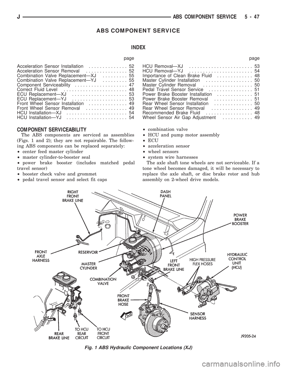
COMPONENT SERVICEABILITY
The ABS components are serviced as assemblies
(Figs. 1 and 2); they are not repairable. The follow-
ing ABS components can be replaced separately:
²center feed master cylinder
²master cylinder-to-booster seal
²power brake booster (includes matched pedal
travel sensor)
²booster check valve and grommet
²pedal travel sensor and select fit caps²combination valve
²HCU and pump motor assembly
²ECU
²acceleration sensor
²wheel sensors
²system wire harnesses
The axle shaft tone wheels are not serviceable. If a
tone wheel becomes damaged, it will be necessary to
replace the axle shaft, or disc brake rotor and hub
assembly on 2-wheel drive models.
Fig. 1 ABS Hydraulic Component Locations (XJ)
JABS COMPONENT SERVICE 5 - 47
Page 196 of 1784
Clean the reservoir and caps thoroughly before
checking level or adding fluid. Cap open lines and
hoses during service to prevent dirt entry.
Dirt or foreign material entering the ABS hydrau-
lic system through the reservoir opening will circu-
late within the system. The result will be poor brake
performance and possible component failure. Use
clean, fresh fluid only to top off, or refill the system.
WHEEL SENSOR AIR GAP ADJUSTMENT
Only rear sensor air gap is adjustable. The front
sensors are fixed and cannot be adjusted.
A rear sensor air gap adjustment is only
needed when reinstalling an original sensor. Re-
placement sensors have an air gap spacer at-
tached to the sensor pickup face. The spacer
establishes correct air gap when pressed against
the tone ring during installation. As the tone
ring rotates, it peels the spacer off the sensor to
create the required air gap.
Preferred rear sensor air gap is 1.1 mm (0.043 in.).
Acceptable air gap range is 0.92 to 1.275 mm (0.036
to 0.050 in.).
Front sensor air gap is not adjustable. The front
sensors are fixed in position and cannot be adjusted.
Front sensor air gap can only be checked. Air gap
should be 0.040 to 1.3 mm (0.0157 to 0.051 in.). If
front sensor air gap is incorrect, the sensor is either
loose, or damaged.
FRONT WHEEL SENSOR REMOVAL
(1) Raise vehicle and turn wheel outward for eas-
ier access to sensor.
(2) Remove sensor wire from mounting brackets.
(3) Clean sensor and surrounding area before removal.
(4) Remove bolt attaching sensor to steering
knuckle and remove sensor.
(5) Unseat grommet retaining sensor wire in wheel
house panel.
(6) In engine compartment, disconnect sensor wire con-
nector at harness plug. Then remove sensor and wire.
FRONT WHEEL SENSOR INSTALLATION
(1) Apply Mopar Lock N' Seal or Loctite 242 to
bolt that attaches sensor to steering knuckle. Use
new sensor bolt if original bolt is worn or damaged.
(2) Position sensor on steering knuckle. Seat sen-
sor locating tab in hole in knuckle and install sensor
attaching bolt finger tight.
(3) Tighten sensor bolt to 14 NIm (11 ft. lbs.) torque.
(4) Attach sensor wire to steering knuckle bracket
with grommets on sensor wire.
(5) Route sensor wire forward and behind shock
absorber. Then attach sensor wire to spring seat
bracket with grommets on sensor wire.
(6) Route sensor wire to outer sill bracket. Remove
all twists or kinks from wire.(7) Attach sensor wire to sill bracket with grom-
met. Be sure wire is free of twists and kinks.
(8) Verify sensor wire routing. Wire should loop
forward and above sill bracket. Loose end of wire
should be below sill bracket and towards brake hose.
(9) Seat sensor wire grommet in body panel and
clip wire to brake line at grommet location.
(10) Connect sensor wire to harness in engine com-
partment.
REAR WHEEL SENSOR REMOVAL
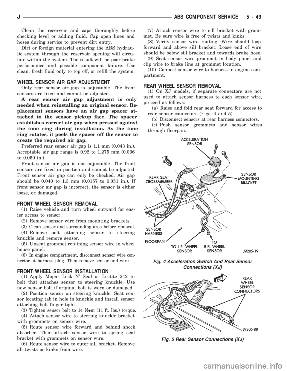
(1) On XJ models, if separate connectors are not
used to attach sensor harness to each sensor wire,
proceed as follows:
(a) Raise and fold rear seat forward for access to
rear sensor connectors (Figs. 4 and 5).
(b) Disconnect sensors at rear harness connectors.
(c) Push sensor grommets and sensor wires
through floorpan.
Fig. 4 Acceleration Switch And Rear Sensor
Connections (XJ)
Fig. 5 Rear Sensor Connections (XJ)
JABS COMPONENT SERVICE 5 - 49
Page 199 of 1784
CAUTION: The pedal travel sensor and booster
must form a matched set. The cap on the sensor
plunger and the color dot on the booster shell are
color coded for identification, and to ensure they
are used as matched sets. Be sure the color on the
sensor cap and booster shell are the same before
installation. Refer to the Sensor Replacement infor-
mation before installing a new or original sensor.
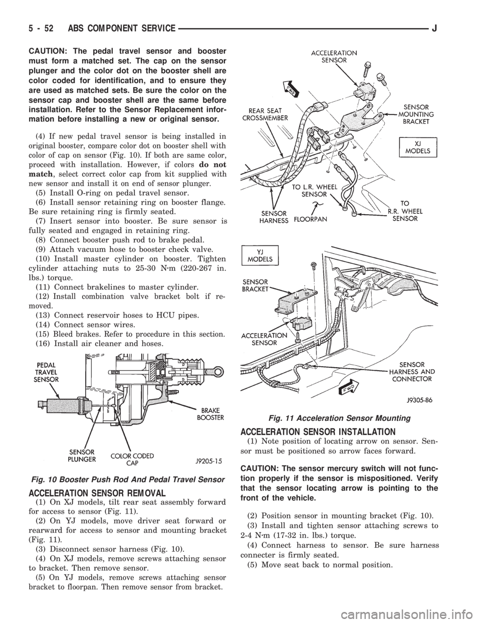
(4) If new pedal travel sensor is being installed in
original booster, compare color dot on booster shell with
color of cap on sensor (Fig. 10). If both are same color,
proceed with installation. However, if colorsdo not
match, select correct color cap from kit supplied with
new sensor and install it on end of sensor plunger.
(5) Install O-ring on pedal travel sensor.
(6) Install sensor retaining ring on booster flange.
Be sure retaining ring is firmly seated.
(7) Insert sensor into booster. Be sure sensor is
fully seated and engaged in retaining ring.
(8) Connect booster push rod to brake pedal.
(9) Attach vacuum hose to booster check valve.
(10) Install master cylinder on booster. Tighten
cylinder attaching nuts to 25-30 Nzm (220-267 in.
lbs.) torque.
(11) Connect brakelines to master cylinder.
(12) Install combination valve bracket bolt if re-
moved.
(13) Connect reservoir hoses to HCU pipes.
(14) Connect sensor wires.
(15) Bleed brakes. Refer to procedure in this section.
(16) Install air cleaner and hoses.
ACCELERATION SENSOR REMOVAL
(1) On XJ models, tilt rear seat assembly forward
for access to sensor (Fig. 11).
(2) On YJ models, move driver seat forward or
rearward for access to sensor and mounting bracket
(Fig. 11).
(3) Disconnect sensor harness (Fig. 10).
(4) On XJ models, remove screws attaching sensor
to bracket. Then remove sensor.
(5) On YJ models, remove screws attaching sensor
bracket to floorpan. Then remove sensor from bracket.
ACCELERATION SENSOR INSTALLATION
(1) Note position of locating arrow on sensor. Sen-
sor must be positioned so arrow faces forward.
CAUTION: The sensor mercury switch will not func-
tion properly if the sensor is mispositioned. Verify
that the sensor locating arrow is pointing to the
front of the vehicle.
(2) Position sensor in mounting bracket (Fig. 10).
(3) Install and tighten sensor attaching screws to
2-4 Nzm (17-32 in. lbs.) torque.
(4) Connect harness to sensor. Be sure harness
connecter is firmly seated.
(5) Move seat back to normal position.
Fig. 10 Booster Push Rod And Pedal Travel Sensor
Fig. 11 Acceleration Sensor Mounting
5 - 52 ABS COMPONENT SERVICEJ
Page 203 of 1784
PARKING BRAKES
INDEX
page page
General Service Information................ 56
Parking Brake Adjustment (XJ/YJ)............ 63
Parking Brake Cable Tensioner Replacement (XJ).61
Parking Brake Front Cable Replacement (YJ) . . . 62
Parking Brake Lever Installation
(XJ with Full Console)................... 60
Parking Brake Lever Installation
(XJ with Mini Console)................... 58
Parking Brake Lever Installation
(XJ Without Console).................... 60
Parking Brake Lever Removal
(XJ with Full Console).................... 59
Parking Brake Lever Removal
(XJ with Mini Console)................... 58
Parking Brake Lever Removal (XJ Without Console).60
Parking Brake Operation................... 56
Parking Brake Pedal Installation (YJ).......... 61
Parking Brake Pedal Removal (YJ)........... 61
Parking Brake Rear Cable Replacement (XJ) . . . 62
Parking Brake Rear Cable Replacement (YJ) . . . 63
GENERAL SERVICE INFORMATION
Parking brake adjustment is controlled by a
cable tensioner mechanism. The tensioner mech-
anism is used on 1991 through 1994 YJ models
and XJ models starting with 1992 models. The
cable tensioner, once adjusted at the factory,
will not need further adjustment under normal
circumstances. There are only two instances
when adjustment is required. The first is when a
new tensioner, or cables have been installed.
And the second, is when the tensioner and ca-
bles are disconnected for access to other brake
components.
PARKING BRAKE OPERATION
The rear brakes are utilized for the parking brake
function. They are actuated hydraulically during nor-
mal brake operation but are mechanically actuated
for parking brake operation.
Parking Brake Components
The rear brakeshoes are applied by a system of le-
vers and cables for parking brake operation. A foot
or hand operated lever in the passenger compartment
is the main application device. Actuating levers on
the secondary brakeshoes move the shoes directly
into contact with the drum braking surface. The ac-
tuating levers are interconnected by a system of ca-
bles and a tensioner mechanism. The tensioner
mechanism controls parking brake adjustment.
On XJ models, the cable tensioner is part of the le-
ver assembly. On YJ models, the tensioner and
equalizer are mounted in a bracket attached to the
underbody.
On YJ models, the parking brake front cable is at-
tached to the foot pedal at one end and the cable ten-
sioner at the other. The tensioner is connected to the
equalizer which is the connecting device for the rear
cables (Fig. 1).
On XJ models, the cable tensioner is connected di-rectly to the hand lever (a front cable is not used).
The tensioner rod is attached to the equalizer which
is the connecting point for the rear cables (Fig. 2).
The rear cables are connected to the actuating le-
ver on each secondary brakeshoe. The levers are at-
tached to the brakeshoes by a pin either pressed into,
or welded to the lever. A clip is used to secure the
pin in the brakeshoe. The pin allows each lever to
pivot independently of the brakeshoe.
Struts, installed between each brakeshoe, are used
to maintain shoe alignment and equal motion when
the parking brakes are applied. Each strut is
equipped with a combination tension and anti-rattle
spring.
Parking Brake Application
To apply the parking brakes, the foot pedal is
pressed downward, or the hand lever is pulled up-
ward, to an engaged position. This pulls the rear
brakeshoe actuating levers forward, by means of the
interconnected tensioner and cables.
As the actuating lever is pulled forward, the park-
ing brake strut (which is connected to both shoes),
exerts a linear force against the primary brakeshoe.
This action presses the primary shoe into contact
with the drum.
Once the primary shoe contacts the brake drum,
force exerted through the strut does not end. Instead,
further lever movement continues to exert force
against the strut; only this time, in a reverse direc-
tion. The strut force then causes the secondary shoe
to pivot into contact with the drum as well.
The brakeshoes will remain engaged with the
drum until the levers and cables are released. A gear
type ratcheting mechanism is used to hold the pedal
or lever in an applied position. Parking brake release
is accomplished by means of the release handle on
YJ models. Or by the hand lever release button on
XJ models.
5 - 56 PARKING BRAKESJ
Page 208 of 1784
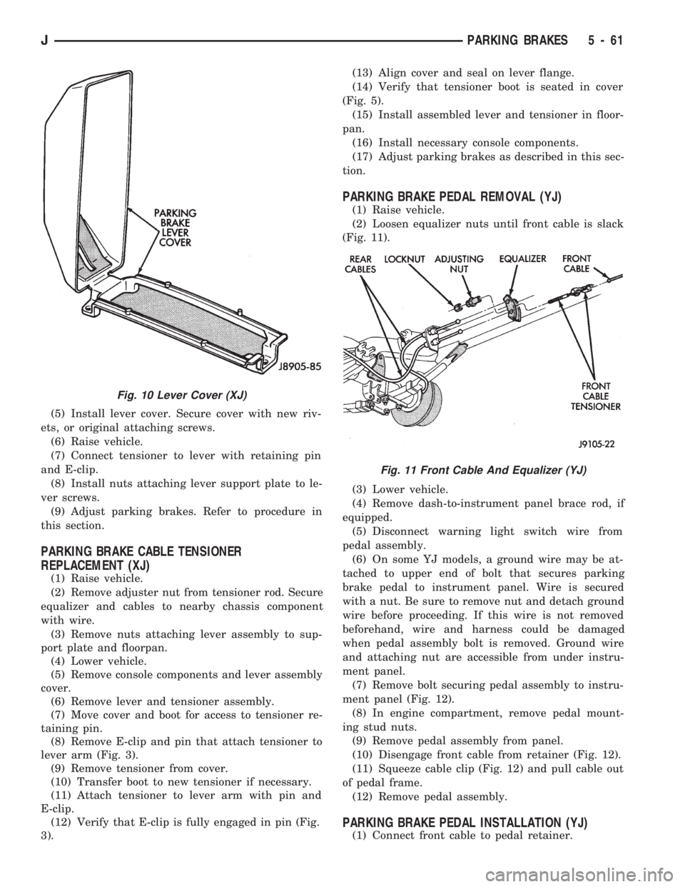
(5) Install lever cover. Secure cover with new riv-
ets, or original attaching screws.
(6) Raise vehicle.
(7) Connect tensioner to lever with retaining pin
and E-clip.
(8) Install nuts attaching lever support plate to le-
ver screws.
(9) Adjust parking brakes. Refer to procedure in
this section.
PARKING BRAKE CABLE TENSIONER
REPLACEMENT (XJ)
(1) Raise vehicle.
(2) Remove adjuster nut from tensioner rod. Secure
equalizer and cables to nearby chassis component
with wire.
(3) Remove nuts attaching lever assembly to sup-
port plate and floorpan.
(4) Lower vehicle.
(5) Remove console components and lever assembly
cover.
(6) Remove lever and tensioner assembly.
(7) Move cover and boot for access to tensioner re-
taining pin.
(8) Remove E-clip and pin that attach tensioner to
lever arm (Fig. 3).
(9) Remove tensioner from cover.
(10) Transfer boot to new tensioner if necessary.
(11) Attach tensioner to lever arm with pin and
E-clip.
(12) Verify that E-clip is fully engaged in pin (Fig.
3).(13) Align cover and seal on lever flange.
(14) Verify that tensioner boot is seated in cover
(Fig. 5).
(15) Install assembled lever and tensioner in floor-
pan.
(16) Install necessary console components.
(17) Adjust parking brakes as described in this sec-
tion.
PARKING BRAKE PEDAL REMOVAL (YJ)
(1) Raise vehicle.
(2) Loosen equalizer nuts until front cable is slack
(Fig. 11).
(3) Lower vehicle.
(4) Remove dash-to-instrument panel brace rod, if
equipped.
(5) Disconnect warning light switch wire from
pedal assembly.
(6) On some YJ models, a ground wire may be at-
tached to upper end of bolt that secures parking
brake pedal to instrument panel. Wire is secured
with a nut. Be sure to remove nut and detach ground
wire before proceeding. If this wire is not removed
beforehand, wire and harness could be damaged
when pedal assembly bolt is removed. Ground wire
and attaching nut are accessible from under instru-
ment panel.
(7) Remove bolt securing pedal assembly to instru-
ment panel (Fig. 12).
(8) In engine compartment, remove pedal mount-
ing stud nuts.
(9) Remove pedal assembly from panel.
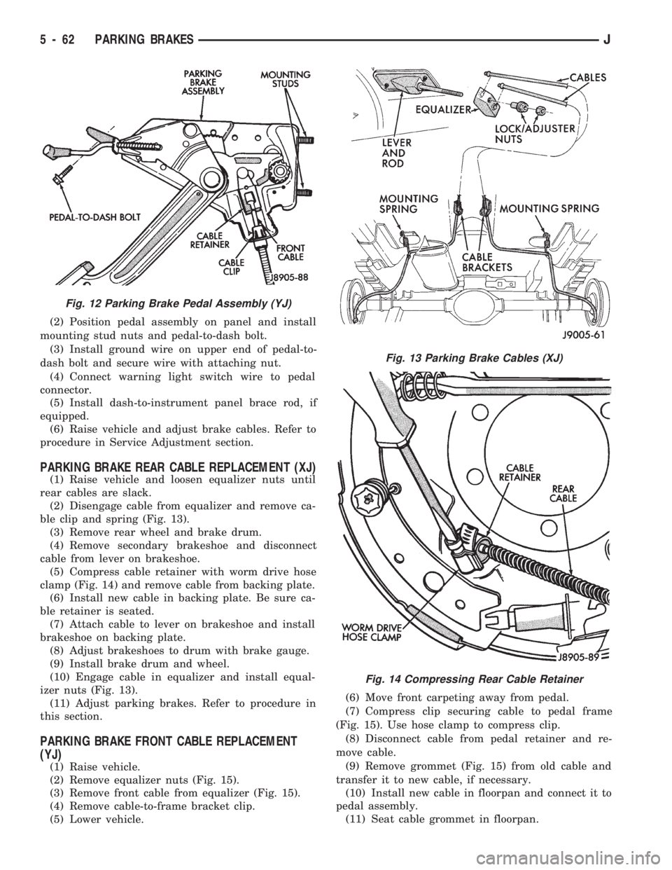
(10) Disengage front cable from retainer (Fig. 12).
(11) Squeeze cable clip (Fig. 12) and pull cable out
of pedal frame.
(12) Remove pedal assembly.
PARKING BRAKE PEDAL INSTALLATION (YJ)
(1) Connect front cable to pedal retainer.
Fig. 10 Lever Cover (XJ)
Fig. 11 Front Cable And Equalizer (YJ)
JPARKING BRAKES 5 - 61
Page 209 of 1784
(2) Position pedal assembly on panel and install
mounting stud nuts and pedal-to-dash bolt.
(3) Install ground wire on upper end of pedal-to-
dash bolt and secure wire with attaching nut.
(4) Connect warning light switch wire to pedal
connector.
(5) Install dash-to-instrument panel brace rod, if
equipped.
(6) Raise vehicle and adjust brake cables. Refer to
procedure in Service Adjustment section.
PARKING BRAKE REAR CABLE REPLACEMENT (XJ)
(1) Raise vehicle and loosen equalizer nuts until
rear cables are slack.
(2) Disengage cable from equalizer and remove ca-
ble clip and spring (Fig. 13).
(3) Remove rear wheel and brake drum.
(4) Remove secondary brakeshoe and disconnect
cable from lever on brakeshoe.
(5) Compress cable retainer with worm drive hose
clamp (Fig. 14) and remove cable from backing plate.
(6) Install new cable in backing plate. Be sure ca-
ble retainer is seated.
(7) Attach cable to lever on brakeshoe and install
brakeshoe on backing plate.
(8) Adjust brakeshoes to drum with brake gauge.
(9) Install brake drum and wheel.
(10) Engage cable in equalizer and install equal-
izer nuts (Fig. 13).
(11) Adjust parking brakes. Refer to procedure in
this section.
PARKING BRAKE FRONT CABLE REPLACEMENT
(YJ)
(1) Raise vehicle.
(2) Remove equalizer nuts (Fig. 15).
(3) Remove front cable from equalizer (Fig. 15).
(4) Remove cable-to-frame bracket clip.
(5) Lower vehicle.(6) Move front carpeting away from pedal.
(7) Compress clip securing cable to pedal frame
(Fig. 15). Use hose clamp to compress clip.
(8) Disconnect cable from pedal retainer and re-
move cable.
(9) Remove grommet (Fig. 15) from old cable and
transfer it to new cable, if necessary.
(10) Install new cable in floorpan and connect it to
pedal assembly.
(11) Seat cable grommet in floorpan.
Fig. 12 Parking Brake Pedal Assembly (YJ)
Fig. 13 Parking Brake Cables (XJ)
Fig. 14 Compressing Rear Cable Retainer
5 - 62 PARKING BRAKESJ
Page 217 of 1784
²input shaft pilot hub
²transmission front bearing retainer slide surface
Never apply grease to any part of the clutch
cover, or disc.
RECOMMENDED LUBRICANTS
Use Mopar multi-purpose grease for the clutch
pedal bushings and pivot shaft. Use Mopar high tem-
perature grease (or equivalent) for all other lubrica-
tion requirements. Apply recommended amounts and
do not overlubricate.
CLUTCH OPERATION
Leverage, spring force and friction are what make
the clutch work. The disc serves as the friction ele-
ment. The diaphragm spring acting on the pressure
plate provides the apply (or clamping) force. And the
pedal, hydraulic linkage, release lever and bearing
provide the leverage.
The clutch cover, which is bolted to the flywheel, is
the component that clamps the disc against the fly-
wheel. The cover is actually an assembly consisting
of the cover, diaphragm spring, pressure plate, and
fulcrum components.
It is the clutch cover pressure plate that actually
clamps the clutch disc against the flywheel. Pressure
plate force is supplied by the diaphragm spring.
The disc has a splined hub for installation on the
transmission input shaft splines. The splined hub is
what connects the disc to the transmission.The clutch linkage uses hydraulic pressure to oper-
ate the clutch. The clutch master cylinder is con-
nected to the clutch pedal and the slave cylinder is
connected to the release lever. In operation, pressing
the clutch pedal develops fluid pressure in the clutch
master cylinder. This pressure is then transmitted
directly to the slave cylinder via the connecting line.
In turn, the slave cylinder operates the clutch release
lever.
The clutch release bearing is mounted on the
transmission front bearing retainer. The bearing is
attached to the release lever which moves the bear-
ing in and out of contact with the diaphragm spring.
In operation, slave cylinder force causes the release
lever to pivot toward the clutch. This action moves
the release bearing into direct contact with the dia-
phragm spring fingers. As additional force is applied,
the release bearing pushes the spring fingers inward
relieving spring force on the pressure plate. At this
point, the clutch disc is disengaged and freewheeling.
The process of clutch re-engagement, is simply the
reverse of what occurs during disengagement. Re-
leasing pedal pressure removes linkage pressure. The
release bearing moves away from the spring which
again applies clamping force on the disc through the
pressure plate.
6 - 2 CLUTCHJ
Page 226 of 1784
RELEASE BEARING REPLACEMENT
(1) Remove transmission as described in Group 21.
(2) Disconnect release bearing from release lever
and remove bearing (Fig. 5).
(3) Inspect bearing slide surface of transmission
front bearing retainer. Replace retainer if slide sur-
face is scored, worn, or cracked.
(4) Inspect release fork and fork pivot. Be sure
pivot is secure and in good condition. Be sure fork is
not distorted or worn. Replace release fork retainer
spring if bent or damaged in any way.
(5) Lubricate crankshaft pilot bearing with Mopar
high temperature bearing grease. Apply grease to
end of long shank, small diameter flat blade screw-
driver. Then insert tool through clutch disc hub to
reach bearing.
(6) Lubricate input shaft splines, bearing retainer
slide surface, fork pivot and release fork pivot sur-face with Mopar high temperature grease.
(7) Install new release bearing. Be sure bearing is
properly secured to release fork.
(8) Install transmission as described in Group 21.
PILOT BEARING REPLACEMENT
(1) Remove transmission. Refer to Group 21 for
procedure.
(2) Remove clutch cover and disc.
(3) Remove pilot bearing. Use internal (blind hole)
puller such those as supplied in Snap On Tool Set
CG40CB to remove bearing.
(4) Lubricate new bearing with Mopar high tem-
perature bearing grease.
(5) Start new bearing into crankshaft by hand.
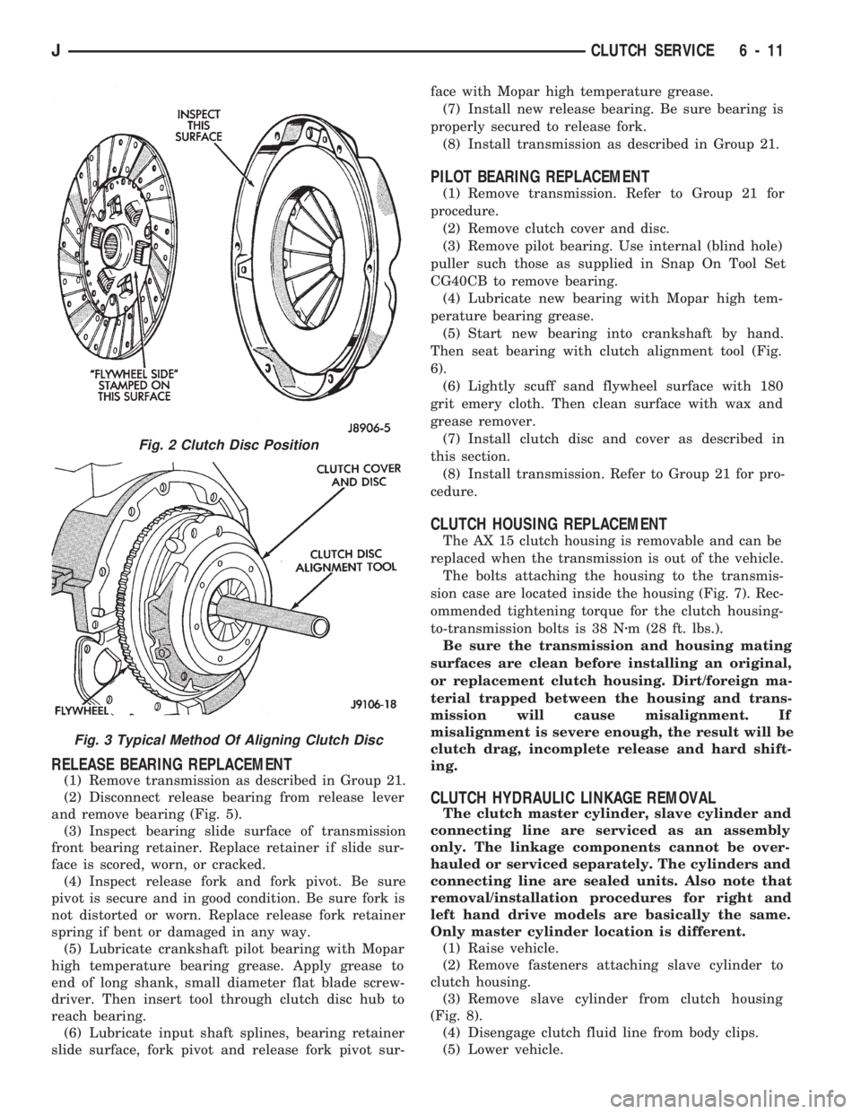
Then seat bearing with clutch alignment tool (Fig.
6).
(6) Lightly scuff sand flywheel surface with 180
grit emery cloth. Then clean surface with wax and
grease remover.
(7) Install clutch disc and cover as described in
this section.
(8) Install transmission. Refer to Group 21 for pro-
cedure.
CLUTCH HOUSING REPLACEMENT
The AX 15 clutch housing is removable and can be
replaced when the transmission is out of the vehicle.
The bolts attaching the housing to the transmis-
sion case are located inside the housing (Fig. 7). Rec-
ommended tightening torque for the clutch housing-
to-transmission bolts is 38 Nzm (28 ft. lbs.).
Be sure the transmission and housing mating
surfaces are clean before installing an original,
or replacement clutch housing. Dirt/foreign ma-
terial trapped between the housing and trans-
mission will cause misalignment. If
misalignment is severe enough, the result will be
clutch drag, incomplete release and hard shift-
ing.
CLUTCH HYDRAULIC LINKAGE REMOVAL
The clutch master cylinder, slave cylinder and
connecting line are serviced as an assembly
only. The linkage components cannot be over-
hauled or serviced separately. The cylinders and
connecting line are sealed units. Also note that
removal/installation procedures for right and
left hand drive models are basically the same.
Only master cylinder location is different.
(1) Raise vehicle.
(2) Remove fasteners attaching slave cylinder to
clutch housing.
(3) Remove slave cylinder from clutch housing
(Fig. 8).
(4) Disengage clutch fluid line from body clips.
(5) Lower vehicle.
Fig. 2 Clutch Disc Position
Fig. 3 Typical Method Of Aligning Clutch Disc
JCLUTCH SERVICE 6 - 11