1994 JEEP CHEROKEE ABS
[x] Cancel search: ABSPage 440 of 1784
(1) Position the vehicle in dark area with a level
floor and with a screen (wall) that has a white sur-
face.
(2) Mark a reference line on the floor 7.62 meters
(25 feet) away from and parallel to the ``aiming''
screen/wall.
(3) Position vehicle with the fog lamps located di-
rectly above the 7.62-meters (25-feet) reference line.
(4) Equalize all the tire pressures.
(5) Rock the vehicle from side to side to stabilize
the springs and shock absorbers.
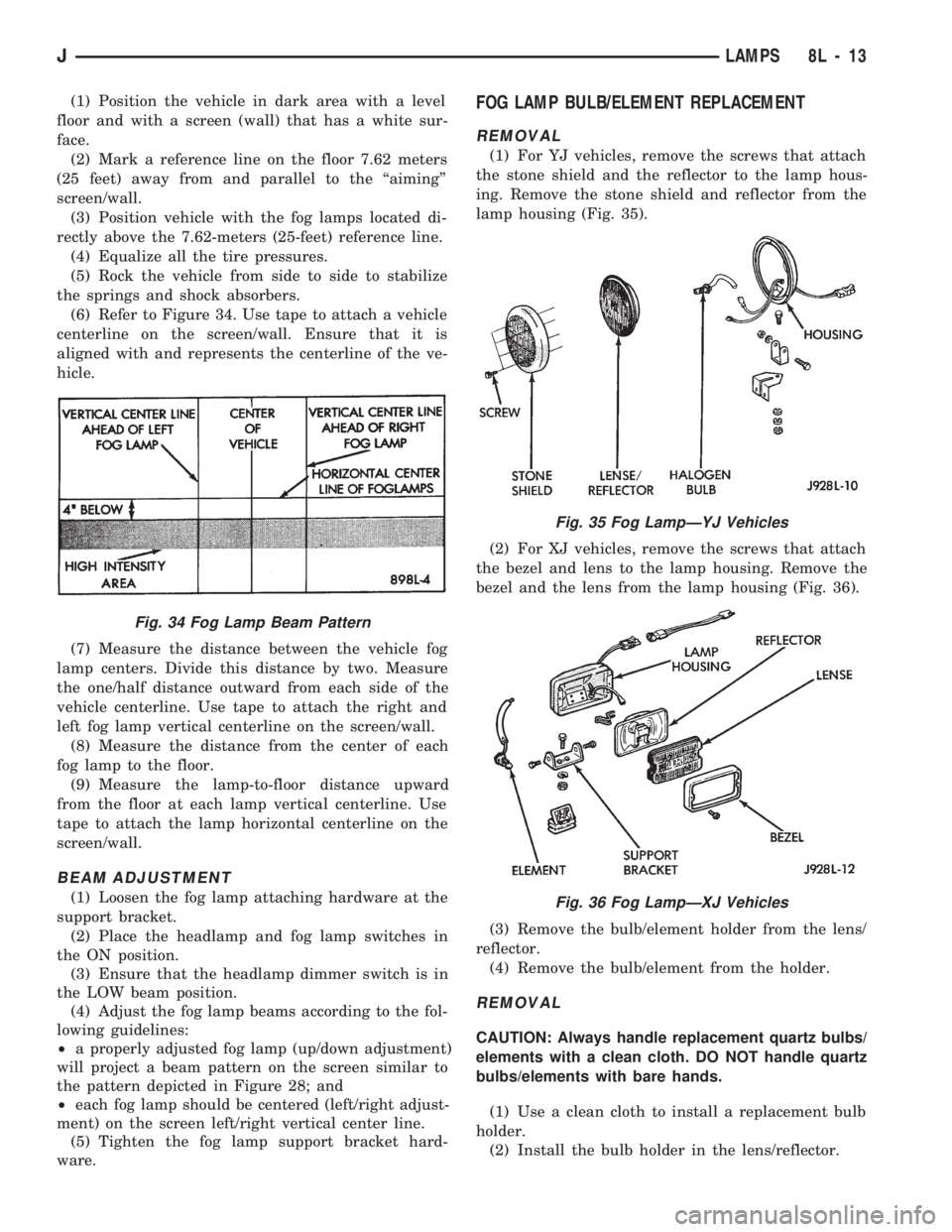
(6) Refer to Figure 34. Use tape to attach a vehicle
centerline on the screen/wall. Ensure that it is
aligned with and represents the centerline of the ve-
hicle.
(7) Measure the distance between the vehicle fog
lamp centers. Divide this distance by two. Measure
the one/half distance outward from each side of the
vehicle centerline. Use tape to attach the right and
left fog lamp vertical centerline on the screen/wall.
(8) Measure the distance from the center of each
fog lamp to the floor.
(9) Measure the lamp-to-floor distance upward
from the floor at each lamp vertical centerline. Use
tape to attach the lamp horizontal centerline on the
screen/wall.
BEAM ADJUSTMENT
(1) Loosen the fog lamp attaching hardware at the
support bracket.
(2) Place the headlamp and fog lamp switches in
the ON position.
(3) Ensure that the headlamp dimmer switch is in
the LOW beam position.
(4) Adjust the fog lamp beams according to the fol-
lowing guidelines:
²a properly adjusted fog lamp (up/down adjustment)
will project a beam pattern on the screen similar to
the pattern depicted in Figure 28; and
²each fog lamp should be centered (left/right adjust-
ment) on the screen left/right vertical center line.
(5) Tighten the fog lamp support bracket hard-
ware.
FOG LAMP BULB/ELEMENT REPLACEMENT
REMOVAL
(1) For YJ vehicles, remove the screws that attach
the stone shield and the reflector to the lamp hous-
ing. Remove the stone shield and reflector from the
lamp housing (Fig. 35).
(2) For XJ vehicles, remove the screws that attach
the bezel and lens to the lamp housing. Remove the
bezel and the lens from the lamp housing (Fig. 36).
(3) Remove the bulb/element holder from the lens/
reflector.
(4) Remove the bulb/element from the holder.
REMOVAL
CAUTION: Always handle replacement quartz bulbs/
elements with a clean cloth. DO NOT handle quartz
bulbs/elements with bare hands.
(1) Use a clean cloth to install a replacement bulb
holder.
(2) Install the bulb holder in the lens/reflector.
Fig. 34 Fog Lamp Beam Pattern
Fig. 35 Fog LampÐYJ Vehicles
Fig. 36 Fog LampÐXJ Vehicles
JLAMPS 8L - 13
Page 441 of 1784
(3) For XJ vehicles, position the bezel and the lens
on the lamp housing. Install the screws that attach
the bezel and lens to the lamp housing. Tighten the
screws securely.
(4) For YJ vehicles, position the stone shield and
reflector on the lamp housing. Install the screws that
attach the stone shield and the reflector to the lamp
housing. Tighten the screws securely.
FOG LAMP SWITCH REPLACEMENT
REMOVALÐXJ VEHICLES
The fog lamp switch is located on the instrument
panel at the left of the steering column.
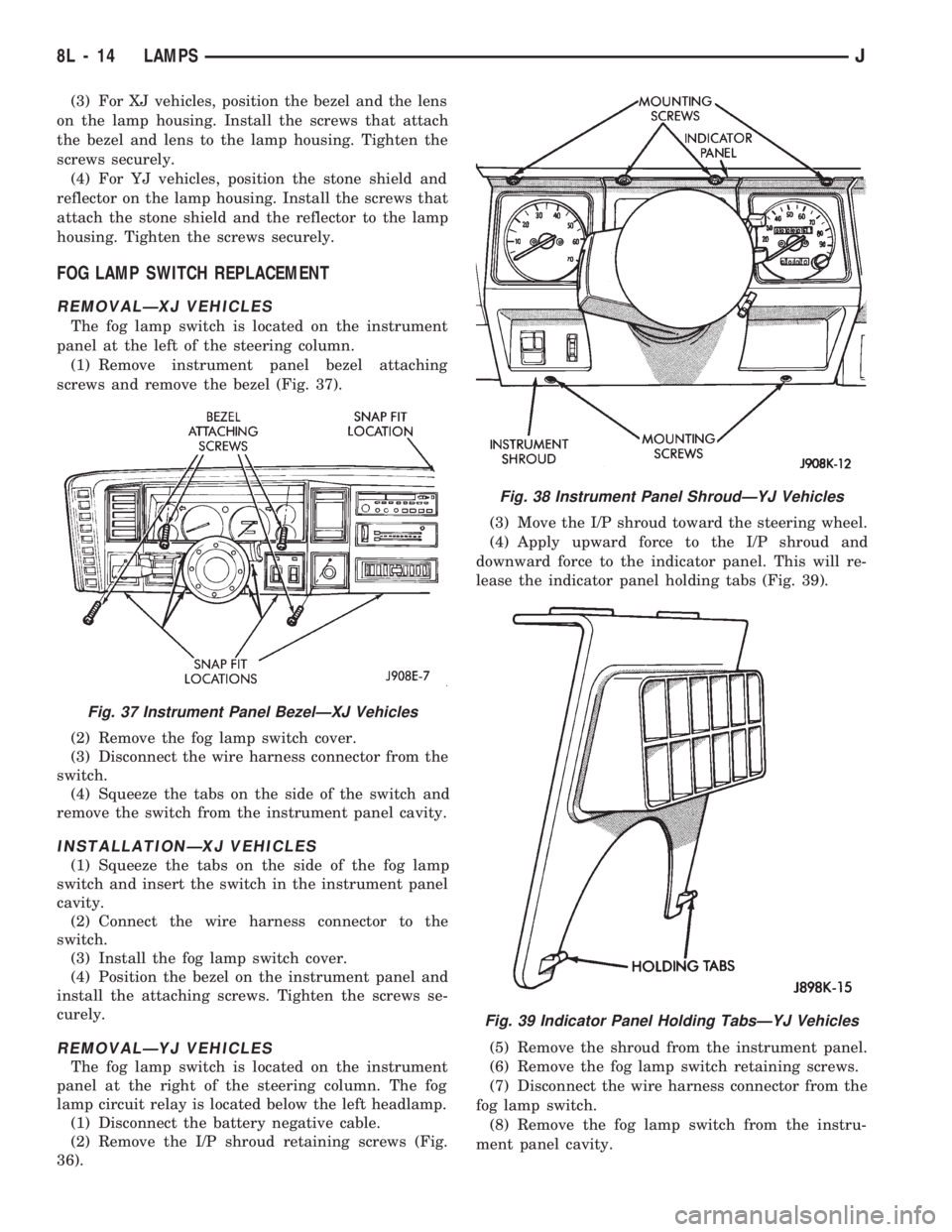
(1) Remove instrument panel bezel attaching
screws and remove the bezel (Fig. 37).
(2) Remove the fog lamp switch cover.
(3) Disconnect the wire harness connector from the
switch.
(4) Squeeze the tabs on the side of the switch and
remove the switch from the instrument panel cavity.
INSTALLATIONÐXJ VEHICLES
(1) Squeeze the tabs on the side of the fog lamp
switch and insert the switch in the instrument panel
cavity.
(2) Connect the wire harness connector to the
switch.
(3) Install the fog lamp switch cover.
(4) Position the bezel on the instrument panel and
install the attaching screws. Tighten the screws se-
curely.
REMOVALÐYJ VEHICLES
The fog lamp switch is located on the instrument
panel at the right of the steering column. The fog
lamp circuit relay is located below the left headlamp.
(1) Disconnect the battery negative cable.
(2) Remove the I/P shroud retaining screws (Fig.
36).(3) Move the I/P shroud toward the steering wheel.
(4) Apply upward force to the I/P shroud and
downward force to the indicator panel. This will re-
lease the indicator panel holding tabs (Fig. 39).
(5) Remove the shroud from the instrument panel.
(6) Remove the fog lamp switch retaining screws.
(7) Disconnect the wire harness connector from the
fog lamp switch.
(8) Remove the fog lamp switch from the instru-
ment panel cavity.
Fig. 37 Instrument Panel BezelÐXJ Vehicles
Fig. 38 Instrument Panel ShroudÐYJ Vehicles
Fig. 39 Indicator Panel Holding TabsÐYJ Vehicles
8L - 14 LAMPSJ
Page 442 of 1784
INSTALLATIONÐYJ VEHICLES
(1) Position the fog lamp switch in the instrument
panel cavity and connect the wire harness connector
to the switch.
(2) Install the fog lamp switch retaining screws.
Tighten the screws securely.
(3) Position the I/P shroud under the steering col-
umn.
(4) Slide the indicator panel holding tabs into the
shroud notches.
(5) Place the assembled I/P shroud over the indica-
tor lamp foam gasket.
The foam gasket located on the back side of
the indicator panel overlay is fragile. If it is ei-
ther torn or distorted, replace it.
(6) Install and tighten the indicator panel retain-
ing screws.
(7) Install the remaining shroud screws. Tighten
the screws securely.
(8) Connect the battery negative cable.
FOG LAMP REPLACEMENT
REMOVALÐXJ VEHICLES
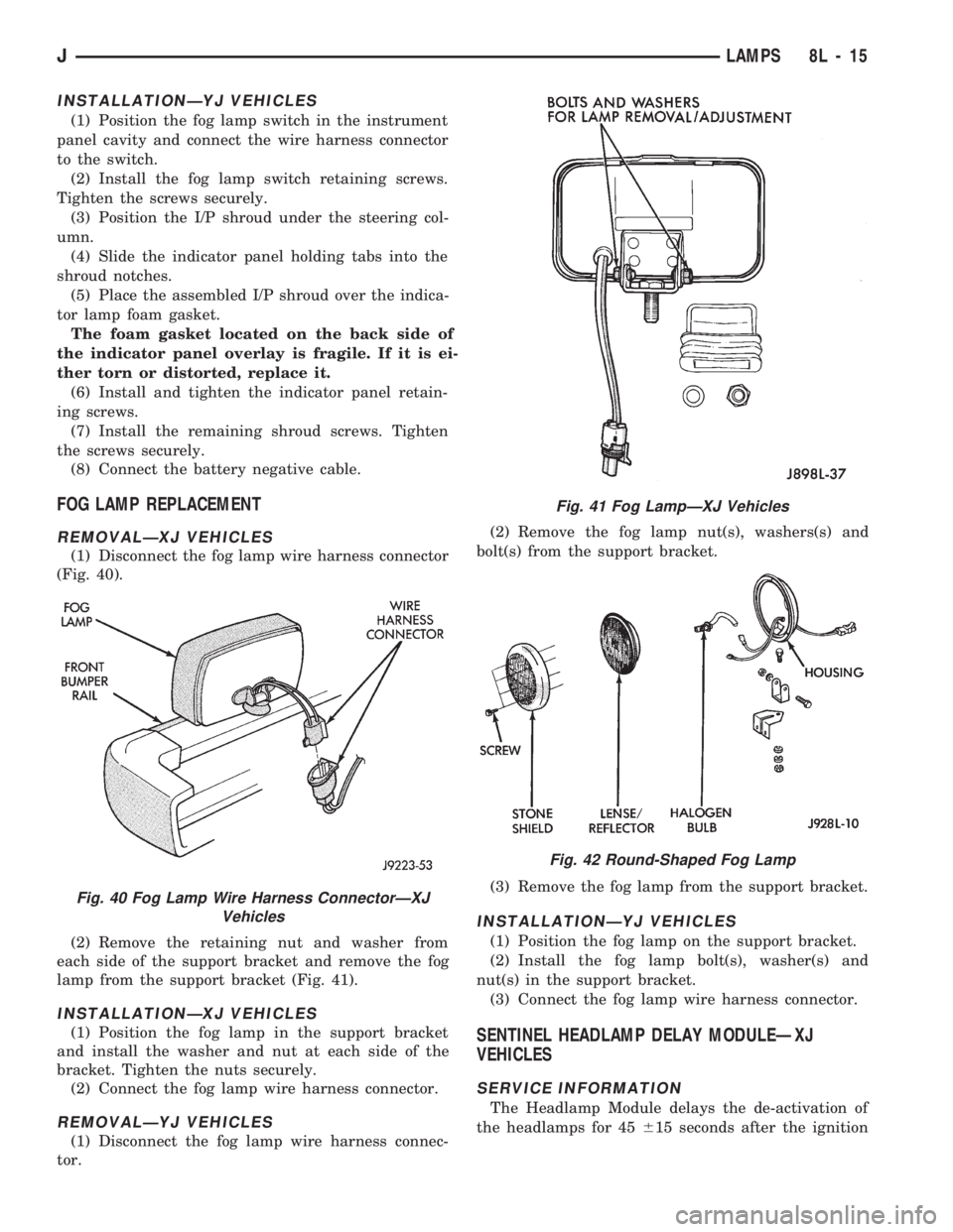
(1) Disconnect the fog lamp wire harness connector
(Fig. 40).
(2) Remove the retaining nut and washer from
each side of the support bracket and remove the fog
lamp from the support bracket (Fig. 41).
INSTALLATIONÐXJ VEHICLES
(1) Position the fog lamp in the support bracket
and install the washer and nut at each side of the
bracket. Tighten the nuts securely.
(2) Connect the fog lamp wire harness connector.
REMOVALÐYJ VEHICLES
(1) Disconnect the fog lamp wire harness connec-
tor.(2) Remove the fog lamp nut(s), washers(s) and
bolt(s) from the support bracket.
(3) Remove the fog lamp from the support bracket.
INSTALLATIONÐYJ VEHICLES
(1) Position the fog lamp on the support bracket.
(2) Install the fog lamp bolt(s), washer(s) and
nut(s) in the support bracket.
(3) Connect the fog lamp wire harness connector.
SENTINEL HEADLAMP DELAY MODULEÐXJ
VEHICLES
SERVICE INFORMATION
The Headlamp Module delays the de-activation of
the headlamps for 45615 seconds after the ignition
Fig. 40 Fog Lamp Wire Harness ConnectorÐXJ
Vehicles
Fig. 41 Fog LampÐXJ Vehicles
Fig. 42 Round-Shaped Fog Lamp
JLAMPS 8L - 15
Page 447 of 1784
(3) Measure the voltage between the pink wire on
the switch connector and vehicle body ground. The
voltmeter should indicate battery voltage. If not OK,
repair the open circuit in the wire harness from the
splice.
(4) Connect a jumper wire from the ground side of
the switch to a good vehicle body ground. Measure
the resistance to vehicle body ground. The ohmmeter
should indicate zero ohms. If not, repair the open cir-
cuit in the wire harness to vehicle body ground.
DOME LAMP REPLACEMENT
REMOVALÐXJ VEHICLES
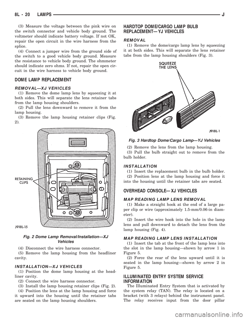
(1) Remove the dome lamp lens by squeezing it at
both sides. This will separate the lens retainer tabs
from the lamp housing shoulders.
(2) Pull the lens downward to remove it from the
lamp housing.
(3) Remove the lamp housing retainer clips (Fig.
2).
(4) Disconnect the wire harness connector.
(5) Remove the lamp housing from the headliner
cavity.
INSTALLATIONÐXJ VEHICLES
(1) Position the dome lamp housing at the head-
liner cavity.
(2) Connect the wire harness connector.
(3) Install the lamp housing retainer clips (Fig. 2).
(4) Position the lens at the lamp housing and force
it upward into the housing until the retainer tabs
are seated on the lamp housing shoulders.
HARDTOP DOME/CARGO LAMP BULB
REPLACEMENTÐYJ VEHICLES
REMOVAL
(1) Remove the dome/cargo lamp lens by squeezing
it at both sides. This will separate the lens retainer
tabs from the lamp housing shoulders (Fig. 3).
(2) Remove the lens from the lamp housing.
(3) Pull the bulb straight out to remove from the
bulb holder.
INSTALLATION
(1) Insert the replacement bulb in the bulb holder.
(2) Position lens at the lamp housing and force it
into the housing until the retainer tabs are seated.
OVERHEAD CONSOLEÐXJ VEHICLES
MAP READING LAMP LENS REMOVAL
(1) Make a straight hook at the end of a large pa-
per clip or wire (approximately 1.5-mm/0.06-in diam-
eter).
(2) Insert the wire hook into the hole in the lamp
lens and pull downward to detach the lens from the
lamp housing (Fig. 4).
MAP READING LAMP LENS INSTALLATION
(1) Insert the tab at the front of the lamp lens into
the slot in the lamp housingÐshown by arrow 1 in
Figure 5.
(2) Force the rear of the lens upward until it is
seated in the lamp housingÐshown by arrow 2 in
Figure 5.
ILLUMINATED ENTRY SYSTEM SERVICE
INFORMATION
The Illuminated Entry System that is activated by
the system relay (TAN). The relay is located on a
bracket (with 3 relays) behind the instrument panel.
The relay receives input from the door pillar
Fig. 2 Dome Lamp Removal/InstallationÐXJ
Vehicles
Fig. 3 Hardtop Dome/Cargo LampÐYJ Vehicles
8L - 20 LAMPSJ
Page 455 of 1784
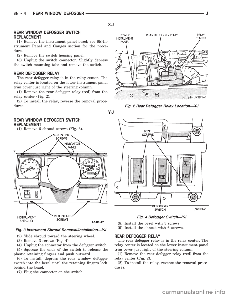
XJ
REAR WINDOW DEFOGGER SWITCH
REPLACEMENT
(1) Remove the instrument panel bezel; see 8E-In-
strument Panel and Gauges section for the proce-
dure.
(2) Remove the switch housing panel.
(3) Unplug the switch connector. Slightly depress
the switch mounting tabs and remove the switch.
REAR DEFOGGER RELAY
The rear defogger relay is in the relay center. The
relay center is located on the lower instrument panel
trim cover just right of the steering column.
(1) Remove the rear defogger relay (red) from the
relay center (Fig. 2).
(2) To install the relay, reverse the removal proce-
dures.
YJ
REAR WINDOW DEFOGGER SWITCH
REPLACEMENT
(1) Remove 6 shroud screws (Fig. 3).
(2) Slide shroud toward the steering wheel.
(3) Remove 3 screws (Fig. 4).
(4) Unplug the connector from the defogger switch.
(5) Squeeze the ends of the switch to release the
plastic retaining fingers and push outward.
(6) To install, depress the rear window defogger
switch into the bezel until the retaining fingers lock
behind the bezel.
(7) Plug the connector on the switch.(8) Install the bezel with 3 screws.
(9) Install the shroud with 6 screws.
REAR DEFOGGER RELAY
The rear defogger relay is in the relay center. The
relay center is located on the lower instrument panel
trim cover just right of the steering column.
(1) Remove the rear defogger relay (red) from the
relay center (Fig. 2).
(2) To install the relay, reverse the removal proce-
dures.
Fig. 2 Rear Defogger Relay LocationÐXJ
Fig. 3 Instrument Shroud Removal/InstallationÐYJ
Fig. 4 Defogger SwitchÐYJ
8N - 4 REAR WINDOW DEFOGGERJ
Page 492 of 1784
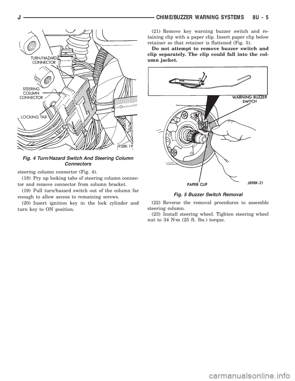
steering column connector (Fig. 4).
(18) Pry up locking tabs of steering column connec-
tor and remove connector from column bracket.
(19) Pull turn/hazard switch out of the column far
enough to allow access to remaining screws.
(20) Insert ignition key in the lock cylinder and
turn key to ON position.(21) Remove key warning buzzer switch and re-
taining clip with a paper clip. Insert paper clip below
retainer so that retainer is flattened (Fig. 5).
Do not attempt to remove buzzer switch and
clip separately. The clip could fall into the col-
umn jacket.
(22) Reverse the removal procedures to assemble
steering column.
(23) Install steering wheel. Tighten steering wheel
nut to 34 Nzm (25 ft. lbs.) torque.
Fig. 4 Turn/Hazard Switch And Steering Column
Connectors
Fig. 5 Buzzer Switch Removal
JCHIME/BUZZER WARNING SYSTEMS 8U - 5
Page 566 of 1784
WIRING DIAGRAMS YJ
ALPHABETICAL INDEX
Wiring Diagram Name Sheet Number
ABS Accelerator Sensor........................59
ABS Control Module.....................57, 58, 59
ABS Control Module Connector...................60
ABS Motor Pump Relay........................57
ABS Power Relay............................57
A/C Blower Switch............................50
A/C Compressor.............................49
A/C Low Pressure Switch.......................49
A/C Relay.................................49
A/C Thermostat..............................50
Accessory Illumination.........................32
Air Conditioning System (4.0L).................49, 50
A/C Blower Switch..........................50
A/C Compressor............................49
A/C Low Pressure Switch.....................49
A/C Relay................................49
A/C Thermostat............................50
Field Jumper..............................50
Powertrain Control Module.....................49
Anti-Lock Brake System (TEVES).............57, 58, 59
ABS Accelerator Sensor.......................59
ABS Control Module....................57, 58, 59
ABS Motor Pump Relay.......................57
ABS Power Relay...........................57
Brake Pedal Travel Sensor.....................57
Data Link Connector.........................57
Diode..................................58
Hydraulic Actuation Unit......................58
Left Front Wheel Sensor......................59
Left Rear Wheel Sensor.......................59
Power Distribution Center.....................57
Pump Motor..............................57
Pump Motor Sensor.........................57
Right Front Wheel Sensor.....................59
Right Rear Wheel Sensor......................59
Automatic Shut-Down Relay...................11, 17
Back-Up Lamps...........................51, 52
Back-Up Lamp Switch..........................7
Battery................................1,3,5
Blower Motor...............................47
Blower Resistor.............................47
Blower Switch..............................47
Body Harness Connector........................36
Brake Pedal Travel Sensor.......................57
Brake Warning Switch..........................9
Bulkhead Connector........................65, 66
Buzzer Module..............................36
Camshaft Position Sensor....................12, 18
Center High Mounted Stop Lamp..................52
Charging System 2.5L Engine...................3,4
Battery..................................3
Generator.................................3
Power Distribution Center......................4Wiring Diagram Name Sheet Number
Charging System 4.0L Engine...................5,6
Battery..................................5
Generator.................................5
Power Distribution Center......................6
Cigar Lighter...............................24
Circuit Breakers
Headlamp Switch.........................1,29
#11 (W/Wiper).....................2,10,38,39
Clock....................................45
Cluster Connector............................41
Crankshaft Position Sensor...................12, 18
Data Link Connector.....................13, 19, 57
Daytime Running Lamp Module...................28
Dimmer Switch............................1,29
Dome and Courtesy Lamps......................35
Dome Lamp..............................35
Left Courtesy Lamp.........................35
Left Front Door Jamb Switch...................35
Right Courtesy Lamp........................35
Right Front Door Jamb Switch..................35
Dome Lamp................................35
Electrically Tuned Radio with Clock.................45
Electrical Schematic of Cluster....................42
Electrical Schematic of Gauge Package..............44
Electronic Speedometer.........................42
Electronic Tachometer..........................42
Engine Coolant Temp Gauge.....................44
Engine Coolant Temperature Sensor..............15, 21
Engine Oil Pressure and Temperature System..........23
Engine Coolant Temperature Sending Unit...........23
Engine Oil Pressure Sending Unit................23
Engine Oil Pressure Gauge......................44
Engine Starter System........................2,7
Back-Up Lamp Switch........................7
Engine Starter Motor.........................7
Engine Starter Relay..........................7
Park/Neutral Position Switch....................7
Engine Wiring Connector (16 Way).................69
4-WD Command Trac Switch......................8
Field Jumper...............................50
Fog Lamp Relays............................30
Fog Lamp Switch............................30
Front End Lighting.........................25, 26
Left Fog Lamp.............................25
Left Headlamp.............................25
Left Park and Turn Signal Lamp.................25
Left Side Marker Lamp.......................25
Right Fog Lamp............................26
Right Headlamp............................26
Right Park and Turn Signal Lamp................26
Right Side Marker Lamp......................26
Front End Lighting (Canada)...................27, 28
Daytime Running Lamp Module.................28
JWIRING DIAGRAMS 8W - 73
Page 568 of 1784
Wiring Diagram Name Sheet Number
Left Back-Up Lamp..........................51
Left Courtesy Lamp.........................35
Left Fog Lamp..........................25, 27
Left Headlamp..........................25, 27
Left Park and Turn Signal Lamp..............25, 27
Left Side Marker Lamp....................25, 27
Left Tail, Stop and Turn Signal Lamp..............51
Right Back-Up Lamp.........................52
Right Courtesy Lamp........................35
Right Fog Lamp.........................26, 28
Right Headlamp.........................26, 28
Right Park and Turn Signal Lamp.............26, 28
Right Side Marker Lamp...................26, 28
Right Tail, Stop and Turn Signal Lamp.............52
Underhood Lamp............................8
Left Back-Up Lamps..........................51
Left Courtesy Lamp...........................35
Left Fog Lamp...........................25, 27
Left Front Door Jamb Switch.....................35
Left Front Speaker............................46
Left Halo Speaker............................46
Left Headlamp............................25, 27
Left Park and Turn Signal Lamp................25, 27
Left Side Marker Lamp......................25, 27
Left Tail, Stop and Turn Signal Lamp...............51
MAP Sensor.............................15, 21
Mercury Switch..............................8
Modules
ABS Control Module....................57, 58, 59
Buzzer Module.............................36
Daytime Running Lamp Module.................28
Intermittent Wiper Module.....................40
Motors
Blower Motor.............................47
Engine Starter Motor.........................7
Idle Air Control Motor.....................14, 20
Rear Wiper Motor..........................37
Wiper Motor...........................38, 39
Oil Pressure and Temp System...................23
Panel Lamp Dimmer Switch......................1
Panel Lamps.............................31, 32
Accessory Illumination........................32
Heater Control Panel Illumination.................32
Panel Lamp Dimmer Switch....................31
Transmission Range Illumination.................32
Park Brake Switch.............................9
Park/Neutral Position Switch......................7
Part Throttle EMCC 3-Speed Automatic Transmission.....56
Part Throttle EMCC Relay.......................56
Part Throttle EMCC Solenoid.....................56
Power Distribution Center.................1,4,6,57
Power Distribution Center Identification Cover..........67
Power Distribution Center Relays..................68
Power Steering Switch.........................14
Powertrain Control Module............11-22, 48, 49, 56
Powertrain Control Module Connector (2.5L Engine)......63
Powertrain Control Module Connector (4.0L Engine)......64
Provisions for A/C (2.5L).......................48Wiring Diagram Name Sheet Number
Radio Illumination Relay........................45
Radio System............................45, 46
Electrically Tuned Radio with Clock...............45
Left Front Speaker..........................46
Left Halo Speaker...........................46
Radio Illumination Relay......................45
Right Front Speaker.........................46
Right Halo Speaker..........................46
Rear Lighting............................51, 52
Center High Mounted Stop Lamp................52
Left Back-Up Lamp..........................51
Left Tail, Stop & Turn Signal Lamp & License Lamp....51
Right Back-Up Lamp.........................52
Right Tail, Stop & Turn Signal Lamp..............52
Rear Wiper/Washer System......................37
Rear Wiper Motor..........................37
Rear Wiper Switch..........................37
Washer Pump.............................37
Relays
A/C ....................................49
ABS Motor Pump Relay.......................57
ABS Power Relay...........................57
Automatic Shut Down Relay.................11, 17
EMCC...................................56
Engine Starter Relay..........................7
Fog Lamp Relays...........................30
Fuel Pump Relay........................11, 17
Heated Rear Window Relay....................54
Horn Relay...............................33
Radio Illumination Relay......................45
Right Back-Up Lamp..........................52
Right Courtesy Lamp..........................35
Right Fog Lamp...........................26, 28
Right Front Door Jamb Switch....................35
Right Front Speaker...........................46
Right Halo Speaker...........................46
Right Headlamp...........................26, 28
Right Park and Turn Signal...................26, 28
Right Side Marker Lamp.....................26, 28
Right Tail, Stop and Turn Signal Lamp..............52
Seat Belt/Ignition Key Warning Buzzer...............36
Seat Belt Switch.............................36
Sensors
ABS Accelerator Sensor.......................59
Brake Pedal Travel Sensor.....................57
Camshaft Position Sensor...................12, 18
Crankshaft Position Sensor..................12, 18
Engine Coolant Temperature Sensor............15, 21
Heated Oxygen Sensor.....................11, 17
Intake Air Temperature Sensor................15, 21
MAP Sensor...........................15, 21
Pump Motor Sensor.........................57
Throttle Position (Sensor)...................15, 21
Vehicle Speed Sensor.....................12, 18
Wheel Sensors............................59
Speakers..................................46
Speedometer...............................42
JWIRING DIAGRAMS 8W - 75