1994 JEEP CHEROKEE ABS
[x] Cancel search: ABSPage 319 of 1784
sensor voltage to change. This change results in a
different input voltage to the PCM. The input volt-
age level supplies the PCM with information. This
relates to ambient barometric pressure during engine
start-up (cranking) and to engine load while the en-
gine is running. The PCM uses this input, along with
inputs from other sensors, to adjust air-fuel mixture.
For more information, refer to Group 14, Fuel Sys-
tem.
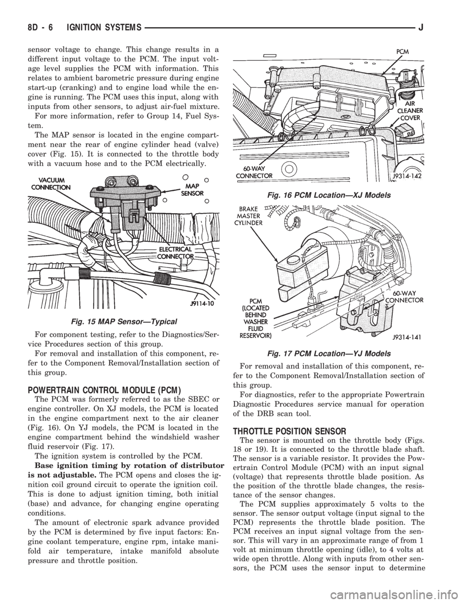
The MAP sensor is located in the engine compart-
ment near the rear of engine cylinder head (valve)
cover (Fig. 15). It is connected to the throttle body
with a vacuum hose and to the PCM electrically.
For component testing, refer to the Diagnostics/Ser-
vice Procedures section of this group.
For removal and installation of this component, re-
fer to the Component Removal/Installation section of
this group.
POWERTRAIN CONTROL MODULE (PCM)
The PCM was formerly referred to as the SBEC or
engine controller. On XJ models, the PCM is located
in the engine compartment next to the air cleaner
(Fig. 16). On YJ models, the PCM is located in the
engine compartment behind the windshield washer
fluid reservoir (Fig. 17).
The ignition system is controlled by the PCM.
Base ignition timing by rotation of distributor
is not adjustable.The PCM opens and closes the ig-
nition coil ground circuit to operate the ignition coil.
This is done to adjust ignition timing, both initial
(base) and advance, for changing engine operating
conditions.
The amount of electronic spark advance provided
by the PCM is determined by five input factors: En-
gine coolant temperature, engine rpm, intake mani-
fold air temperature, intake manifold absolute
pressure and throttle position.For removal and installation of this component, re-
fer to the Component Removal/Installation section of
this group.
For diagnostics, refer to the appropriate Powertrain
Diagnostic Procedures service manual for operation
of the DRB scan tool.
THROTTLE POSITION SENSOR
The sensor is mounted on the throttle body (Figs.
18 or 19). It is connected to the throttle blade shaft.
The sensor is a variable resistor. It provides the Pow-
ertrain Control Module (PCM) with an input signal
(voltage) that represents throttle blade position. As
the position of the throttle blade changes, the resis-
tance of the sensor changes.
The PCM supplies approximately 5 volts to the
sensor. The sensor output voltage (input signal to the
PCM) represents the throttle blade position. The
PCM receives an input signal voltage from the sen-
sor. This will vary in an approximate range of from 1
volt at minimum throttle opening (idle), to 4 volts at
wide open throttle. Along with inputs from other sen-
sors, the PCM uses the sensor input to determine
Fig. 15 MAP SensorÐTypical
Fig. 16 PCM LocationÐXJ Models
Fig. 17 PCM LocationÐYJ Models
8D - 6 IGNITION SYSTEMSJ
Page 321 of 1784

DIAGNOSTICS/SERVICE PROCEDURES
INDEX
page page
Automatic Shut Down (ASD) Relay............ 8
Camshaft Position Sensor Test............... 8
Crankshaft Position Sensor Test.............. 9
Distributor Cap........................... 9
Distributor Rotor......................... 10
DRB Scan Tool.......................... 10
Engine Coolant Temperature Sensor Test...... 12
General Information........................ 8
Ignition Coil............................. 11
Ignition Secondary Circuit Diagnosis.......... 12Ignition Timing........................... 14
Intake Manifold Air Temperature Sensor Test . . . 14
Manifold Absolute Pressure (MAP) Sensor Test . 14
On-Board Diagnostics (OBD)................ 19
Oxygen Sensor Tests..................... 19
Powertrain Control Module (PCM)............ 15
Spark Plug Secondary Cables............... 17
Spark Plugs............................ 16
Throttle Position Sensor Test............... 18
GENERAL INFORMATION
This section of the group, Diagnostics/Service Pro-
cedures, will discuss basic ignition system diagnos-
tics and service adjustments.
For system operation and component identification,
refer to the Component Identification/System Opera-
tion section of this group.
For removal or installation of ignition system com-
ponents, refer to the Component Removal/Installa-
tion section of this group.
For other useful information, refer to On-Board Di-
agnostics in the General Diagnosis sections of Group
14, Fuel System in this manual.
For operation of the DRB Scan Tool, refer to the
appropriate Powertrain Diagnostic Procedures ser-
vice manual.
AUTOMATIC SHUT DOWN (ASD) RELAY
Refer to RelaysÐOperation/Testing in the Group
14, Fuel System section of this service manual.
CAMSHAFT POSITION SENSOR TEST
The camshaft position sensor is located in the dis-
tributor on all engines.
To perform a complete test of this sensor and its
circuitry, refer to the DRB scan tool. Also refer to the
appropriate Powertrain Diagnostics Procedures man-
ual. To test the sensor only, refer to the following:
2.5L OR 4.0L ENGINE
For this test, an analog voltmeter is needed.Do
not remove the distributor connector from the dis-
tributor. Using small paper clips, insert them into
the backside of the distributor wire harness connec-
tor to make contact with the terminals. Be sure that
the connector is not damaged when inserting the pa-
per clips. Attach voltmeter leads to these paper clips.
(1) Connect the positive (+) voltmeter lead into
the sensor output wire. This is at done the distribu-
tor wire harness connector. For wire identification,
refer to Group 8W, Wiring Diagrams.(2) Connect the negative (-) voltmeter lead into the
ground wire. For wire identification, refer to Group
8W, Wiring Diagrams.
(3) Set the voltmeter to the 15 Volt DC scale.
(4) Remove distributor cap. Rotate (crank) engine
with starter until pulse ring (Fig. 1) enters the mag-
netic pickup on camshaft position sensor. Distributor
rotor should be pointed in 9 o'clock position. The
movable pulse ring should now be within the sensor
pickup.
(5) Turn ignition key to ON position. Voltmeter
should read approximately 5.0 volts.
(6) If voltage is not present, check the voltmeter
leads for a good connection.
(7) If voltage is still not present, check for voltage
at the supply wire. For wire identification, refer to
Group 8W, Wiring Diagrams.
Fig. 1 Pulse Ring/Rotor PositionÐTypical
8D - 8 IGNITION SYSTEMSJ
Page 327 of 1784
(10) If spark is not produced, replace the ignition
coil.
IGNITION TIMING
Base (initial) ignition timing is NOT adjustable
on any of the 2.5L 4 cylinder or 4.0L 6 cylinder
engines. Do not attempt to adjust ignition timing
by rotating the distributor.
Do not attempt to modify the distributor hous-
ing to get distributor rotation. Distributor posi-
tion will have no effect on ignition timing.
All ignition timing functions are controlled by the
powertrain control module (PCM). Refer to On-Board
Diagnostics in the Multi-Port Fuel InjectionÐGen-
eral Diagnosis section of Group 14, Fuel Systems for
more information. Also refer to the appropriate Pow-
ertrain Diagnostics Procedures service manual for
operation of the DRB Scan Tool.
INTAKE MANIFOLD AIR TEMPERATURE SENSOR
TEST
To perform a complete test of this sensor and its
circuitry, refer to the DRB scan tool. Also refer to the
appropriate Powertrain Diagnostics Procedures man-
ual. To test the sensor only, refer to the following:
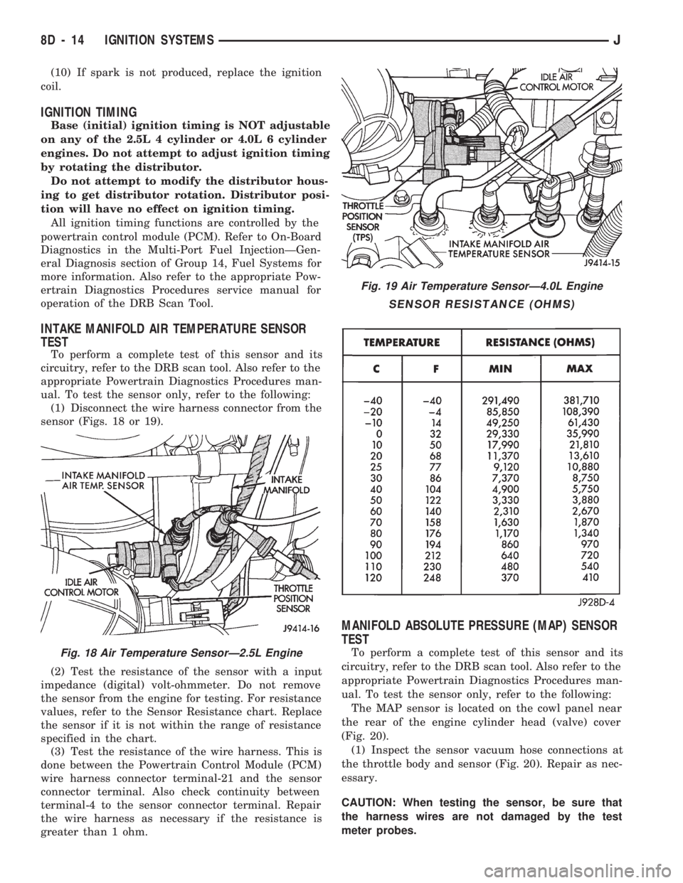
(1) Disconnect the wire harness connector from the
sensor (Figs. 18 or 19).
(2) Test the resistance of the sensor with a input
impedance (digital) volt-ohmmeter. Do not remove
the sensor from the engine for testing. For resistance
values, refer to the Sensor Resistance chart. Replace
the sensor if it is not within the range of resistance
specified in the chart.
(3) Test the resistance of the wire harness. This is
done between the Powertrain Control Module (PCM)
wire harness connector terminal-21 and the sensor
connector terminal. Also check continuity between
terminal-4 to the sensor connector terminal. Repair
the wire harness as necessary if the resistance is
greater than 1 ohm.
MANIFOLD ABSOLUTE PRESSURE (MAP) SENSOR
TEST
To perform a complete test of this sensor and its
circuitry, refer to the DRB scan tool. Also refer to the
appropriate Powertrain Diagnostics Procedures man-
ual. To test the sensor only, refer to the following:
The MAP sensor is located on the cowl panel near
the rear of the engine cylinder head (valve) cover
(Fig. 20).
(1) Inspect the sensor vacuum hose connections at
the throttle body and sensor (Fig. 20). Repair as nec-
essary.
CAUTION: When testing the sensor, be sure that
the harness wires are not damaged by the test
meter probes.Fig. 18 Air Temperature SensorÐ2.5L Engine
Fig. 19 Air Temperature SensorÐ4.0L Engine
SENSOR RESISTANCE (OHMS)
8D - 14 IGNITION SYSTEMSJ
Page 333 of 1784
COMPONENT REMOVAL/INSTALLATION
INDEX
page page
Automatic Shut Down (ASD) Relay........... 20
Camshaft Position Sensor.................. 20
Crankshaft Position Sensor................. 21
Distributor.............................. 23
Engine Coolant Temperature Sensor.......... 22
General Information....................... 20
Ignition Coil............................. 26Intake Manifold Air Temperature Sensor....... 27
Manifold Absolute Pressure (MAP) Sensor..... 27
Oxygen (O2S) Sensor..................... 28
Powertrain Control Module (PCM)............ 28
Spark Plug Secondary Cables............... 29
Spark Plugs............................ 28
Throttle Position Sensor (TPS).............. 29
GENERAL INFORMATION
This section of the group, Component Removal/In-
stallation, will discuss the removal and installation
of ignition system components.
For basic ignition system diagnostics and service
adjustments, refer to the Diagnostics/Service Proce-
dures section of this group.
For system operation and component identification,
refer to the Component Identification/System Opera-
tion section of this group.
AUTOMATIC SHUT DOWN (ASD) RELAY
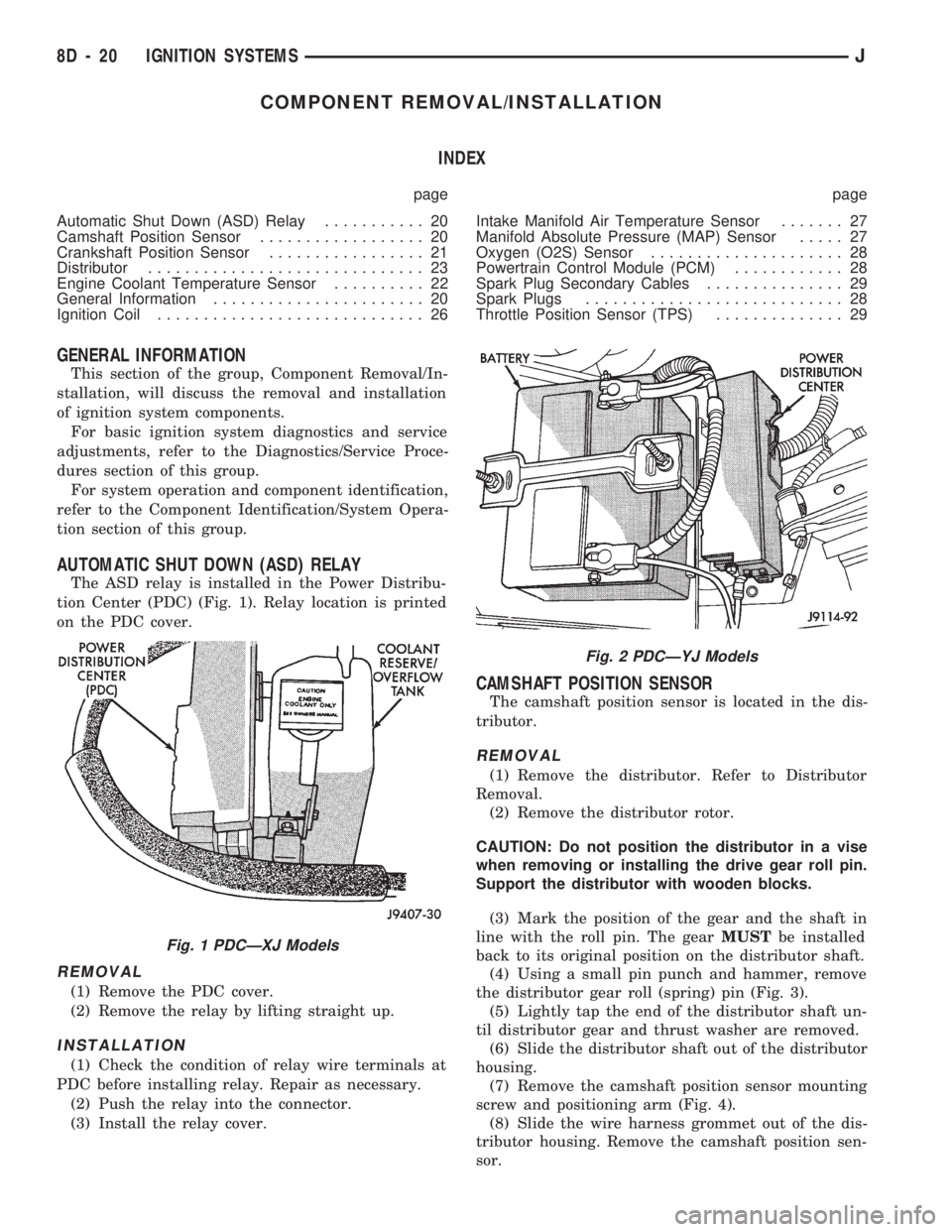
The ASD relay is installed in the Power Distribu-
tion Center (PDC) (Fig. 1). Relay location is printed
on the PDC cover.
REMOVAL
(1) Remove the PDC cover.
(2) Remove the relay by lifting straight up.
INSTALLATION
(1) Check the condition of relay wire terminals at
PDC before installing relay. Repair as necessary.
(2) Push the relay into the connector.
(3) Install the relay cover.
CAMSHAFT POSITION SENSOR
The camshaft position sensor is located in the dis-
tributor.
REMOVAL
(1) Remove the distributor. Refer to Distributor
Removal.
(2) Remove the distributor rotor.
CAUTION: Do not position the distributor in a vise
when removing or installing the drive gear roll pin.
Support the distributor with wooden blocks.
(3) Mark the position of the gear and the shaft in
line with the roll pin. The gearMUSTbe installed
back to its original position on the distributor shaft.
(4) Using a small pin punch and hammer, remove
the distributor gear roll (spring) pin (Fig. 3).
(5) Lightly tap the end of the distributor shaft un-
til distributor gear and thrust washer are removed.
(6) Slide the distributor shaft out of the distributor
housing.
(7) Remove the camshaft position sensor mounting
screw and positioning arm (Fig. 4).
(8) Slide the wire harness grommet out of the dis-
tributor housing. Remove the camshaft position sen-
sor.
Fig. 1 PDCÐXJ Models
Fig. 2 PDCÐYJ Models
8D - 20 IGNITION SYSTEMSJ
Page 340 of 1784
REMOVAL
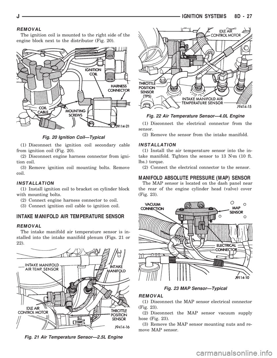
The ignition coil is mounted to the right side of the
engine block next to the distributor (Fig. 20).
(1) Disconnect the ignition coil secondary cable
from ignition coil (Fig. 20).
(2) Disconnect engine harness connector from igni-
tion coil.
(3) Remove ignition coil mounting bolts. Remove
coil.
INSTALLATION
(1) Install ignition coil to bracket on cylinder block
with mounting bolts.
(2) Connect engine harness connector to coil.
(3) Connect ignition coil cable to ignition coil.
INTAKE MANIFOLD AIR TEMPERATURE SENSOR
REMOVAL
The intake manifold air temperature sensor is in-
stalled into the intake manifold plenum (Figs. 21 or
22).(1) Disconnect the electrical connector from the
sensor.
(2) Remove the sensor from the intake manifold.
INSTALLATION
(1) Install the air temperature sensor into the in-
take manifold. Tighten the sensor to 13 Nzm (10 ft.
lbs.) torque.
(2) Connect the electrical connector to the sensor.
MANIFOLD ABSOLUTE PRESSURE (MAP) SENSOR
The MAP sensor is located on the dash panel near
the rear of the engine cylinder head (valve) cover
(Fig. 23).
REMOVAL
(1) Disconnect the MAP sensor electrical connector
(Fig. 23).
(2) Disconnect the MAP sensor vacuum supply
hose (Fig. 23).
(3) Remove the MAP sensor mounting nuts and re-
move MAP sensor.
Fig. 20 Ignition CoilÐTypical
Fig. 21 Air Temperature SensorÐ2.5L Engine
Fig. 22 Air Temperature SensorÐ4.0L Engine
Fig. 23 MAP SensorÐTypical
JIGNITION SYSTEMS 8D - 27
Page 349 of 1784
other side. When coolant temperature is too high the
switch closes providing a path to ground, and the indi-
cator bulb lights.
TACHOMETER
The tachometer displays the engine speed (RPM).
With the engine running, the tachometer receives an
engine speed signal from the Powertrain Control
Module pin 43 (values shown in Specifications chart).
SPEEDOMETER/ODOMETER SYSTEM
The speedometer/odometer system consists of an elec-
tric speedometer and pushbutton reset odometer
mounted in the cluster. The system also includes the
wire harness from the cluster to the vehicle speed sen-
sor at the transmission, and the adapter and pinion in
the transmission. A signal is sent from a transmission
mounted vehicle speed sensor to the speedometer/odom-
eter circuitry through the wiring harness. Refer to
Group 21 - Transmission for selecting the proper pinion,
and selecting and indexing the proper adapter.
FUEL GAUGE
The fuel gauge pointer position is controlled by a
magnetic field created by electrical current flow through
the coils within the gauge. A change in current flow will
change the magnetic field which changes the pointer po-
sition. The fuel level sender is a variable resistor that
changes electrical resistance with a change of the level
of fuel in the tank (values shown in Specifications
chart).
LOW FUEL WARNING LAMP
The low fuel warning lamp will light when the fuel
level falls below approximately 4 gallons. A low fuel
warning module controls when the lamp will light.
When the module senses 66.5 ohms or less from the
fuel level sender for 10 continuous seconds, the lamp
will light. The lamp will remain on until the module
senses 63.5 ohms or more from the fuel level sender
for 20 continuous seconds.
UPSHIFT INDICATOR LAMP
Vehicles equipped with manual transmissions have an
optional upshift indicator lamp. The lamp is controlled
by the Powertrain Control Module. The lamp lights to
indicate when the driver should shift to the next high-
est gear for best fuel economy. The Powertrain Control
Module will turn the lamp off after 3 to 5 seconds if the
upshift is not performed. The lamp will remain off until
the vehicle stops accelerating and is brought back to the
range of lamp operation or shifted into another gear.
The indicator lamp is normally illuminated when
the ignition switch is turned ON and is turned off
when the engine is started. The lamp will be lighted
during engine operation according to engine speed
and load.
BRAKE INDICATOR LAMP
The brake indicator lamp warns the driver that the
parking brake is applied or that hydraulic pressure in
the split brake system is unequal.
Voltage is supplied through the brake indicator
bulb to 3 switches. A path to ground for the current
is available if:
²The brake warning switch is closed (with unequal
brake system hydraulic pressures), or
²
The ignition switch is in the START position (to test
the bulb), or
²The park brake switch is closed (with the parking
brake applied).
ANTI-LOCK BRAKE SYSTEM (ABS) INDICATOR
LAMP
The anti-lock brake system (ABS) lamp lights to in-
dicate a system self-check is in process at vehicle
start-up. If light remains on after start-up or comes
on and stays on while driving, it may indicate that
the ABS system has detected a malfunction or has
become inoperative.
4WD INDICATOR LAMP
COMMAND-TRAC 4WD
The PART TIME lamp lights when the vehicle is en-
gaged in four-wheel drive mode. Voltage is supplied to
one side of the indicator bulb. A switch in the transfer
case area is connected to the other side of the indicator
bulb. When the switch is closed, a path to ground is pro-
vided and the indicator bulb lights.
SELECT-TRAC 4WD
The four-wheel drive icon or FULL TIME lamp
lights when the vehicle is engaged in full time four-
wheel drive mode. The PART TIME lamp lights when
the vehicle is in part time four-wheel drive mode.
Voltage is supplied to one side of the indicators.
Switches in the transfer case area are connected to
the other side of the indicator bulbs. When a switch
is closed, a path to ground is provided and the indi-
cator bulb lights.
MALFUNCTION INDICATOR LAMP (CHECK ENGINE)
The Malfunction Indicator Lamp (Check Engine)
lights each time the ignition switch is turned ON and
stays on for 3 seconds as a bulb test.
If the PCM receives an incorrect signal or no signal
from certain sensors or emission related systems the
lamp is turned on (pin 32 of PCM). This is a warning
that the PCM has recorded a system or sensor mal-
function. In some cases when a diagnostic trouble
code is declared the PCM will go into a limp-in mode
in an attempt to keep the system operating. It sig-
nals an immediate need for service.
The lamp also can be used to display diagnostic
trouble codes (DTC). Cycle the ignition switch ON,
OFF, ON, OFF, ON within 5 seconds. This will allow
any trouble codes stored in the PCM memory to be
displayed in a series of flashes representing digits.
8E - 2 XJ INSTRUMENT PANEL AND GAUGESJ
Page 368 of 1784
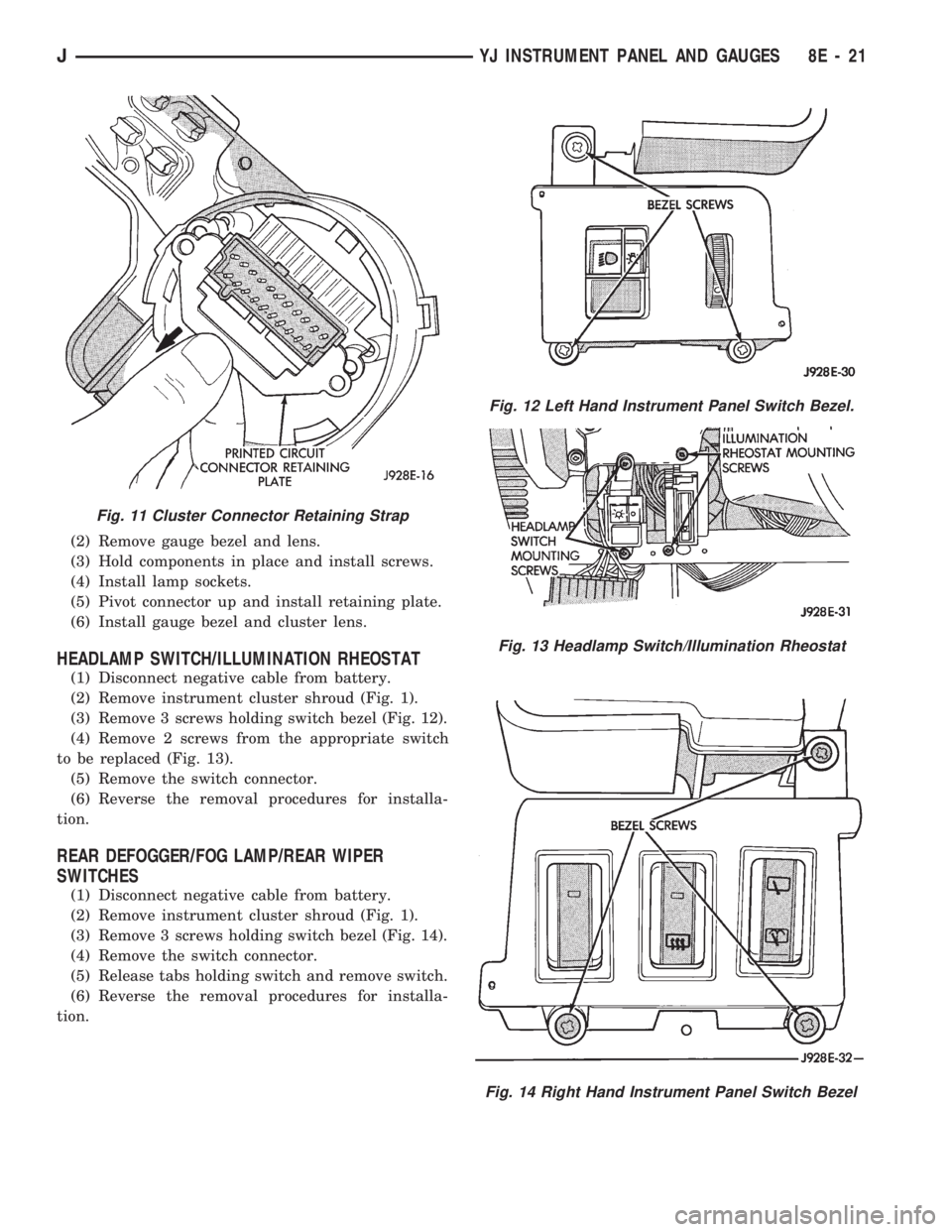
(2) Remove gauge bezel and lens.
(3) Hold components in place and install screws.
(4) Install lamp sockets.
(5) Pivot connector up and install retaining plate.
(6) Install gauge bezel and cluster lens.
HEADLAMP SWITCH/ILLUMINATION RHEOSTAT
(1) Disconnect negative cable from battery.
(2) Remove instrument cluster shroud (Fig. 1).
(3) Remove 3 screws holding switch bezel (Fig. 12).
(4) Remove 2 screws from the appropriate switch
to be replaced (Fig. 13).
(5) Remove the switch connector.
(6) Reverse the removal procedures for installa-
tion.
REAR DEFOGGER/FOG LAMP/REAR WIPER
SWITCHES
(1) Disconnect negative cable from battery.
(2) Remove instrument cluster shroud (Fig. 1).
(3) Remove 3 screws holding switch bezel (Fig. 14).
(4) Remove the switch connector.
(5) Release tabs holding switch and remove switch.
(6) Reverse the removal procedures for installa-
tion.
Fig. 11 Cluster Connector Retaining Strap
Fig. 12 Left Hand Instrument Panel Switch Bezel.
Fig. 13 Headlamp Switch/Illumination Rheostat
Fig. 14 Right Hand Instrument Panel Switch Bezel
JYJ INSTRUMENT PANEL AND GAUGES 8E - 21
Page 398 of 1784
SERVICE PROCEDURES
INDEX
page page
Servo Cable Replacement................... 9
Speed Control Servo Replacement............ 9Speed Control Switch Replacement............ 9
SPEED CONTROL SERVO REPLACEMENT
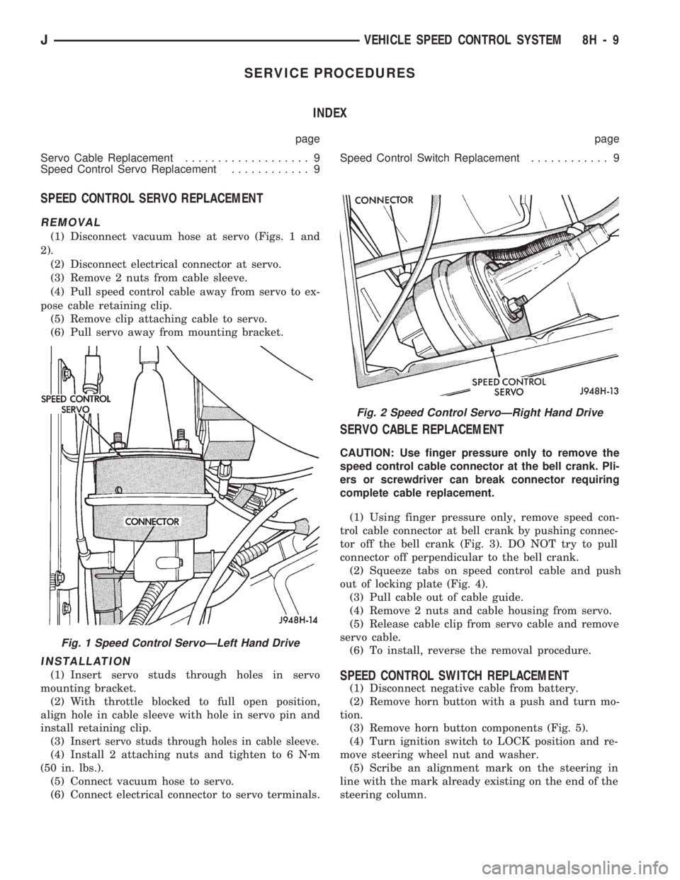
REMOVAL
(1) Disconnect vacuum hose at servo (Figs. 1 and
2).
(2) Disconnect electrical connector at servo.
(3) Remove 2 nuts from cable sleeve.
(4) Pull speed control cable away from servo to ex-
pose cable retaining clip.
(5) Remove clip attaching cable to servo.
(6) Pull servo away from mounting bracket.
INSTALLATION
(1) Insert servo studs through holes in servo
mounting bracket.
(2) With throttle blocked to full open position,
align hole in cable sleeve with hole in servo pin and
install retaining clip.
(3)
Insert servo studs through holes in cable sleeve.
(4) Install 2 attaching nuts and tighten to 6 Nzm
(50 in. lbs.).
(5) Connect vacuum hose to servo.
(6) Connect electrical connector to servo terminals.
SERVO CABLE REPLACEMENT
CAUTION: Use finger pressure only to remove the
speed control cable connector at the bell crank. Pli-
ers or screwdriver can break connector requiring
complete cable replacement.
(1) Using finger pressure only, remove speed con-
trol cable connector at bell crank by pushing connec-
tor off the bell crank (Fig. 3). DO NOT try to pull
connector off perpendicular to the bell crank.
(2) Squeeze tabs on speed control cable and push
out of locking plate (Fig. 4).
(3) Pull cable out of cable guide.
(4) Remove 2 nuts and cable housing from servo.
(5) Release cable clip from servo cable and remove
servo cable.
(6) To install, reverse the removal procedure.
SPEED CONTROL SWITCH REPLACEMENT
(1) Disconnect negative cable from battery.
(2) Remove horn button with a push and turn mo-
tion.
(3) Remove horn button components (Fig. 5).
(4) Turn ignition switch to LOCK position and re-
move steering wheel nut and washer.
(5) Scribe an alignment mark on the steering in
line with the mark already existing on the end of the
steering column.
Fig. 2 Speed Control ServoÐRight Hand Drive
Fig. 1 Speed Control ServoÐLeft Hand Drive
JVEHICLE SPEED CONTROL SYSTEM 8H - 9