1994 JEEP CHEROKEE brakes
[x] Cancel search: brakesPage 1271 of 1784
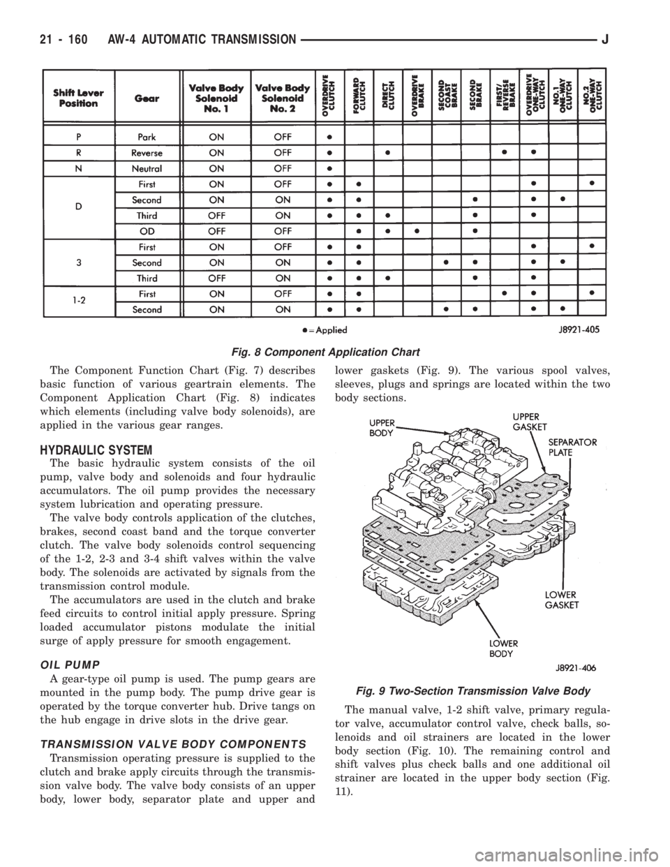
The Component Function Chart (Fig. 7) describes
basic function of various geartrain elements. The
Component Application Chart (Fig. 8) indicates
which elements (including valve body solenoids), are
applied in the various gear ranges.
HYDRAULIC SYSTEM
The basic hydraulic system consists of the oil
pump, valve body and solenoids and four hydraulic
accumulators. The oil pump provides the necessary
system lubrication and operating pressure.
The valve body controls application of the clutches,
brakes, second coast band and the torque converter
clutch. The valve body solenoids control sequencing
of the 1-2, 2-3 and 3-4 shift valves within the valve
body. The solenoids are activated by signals from the
transmission control module.
The accumulators are used in the clutch and brake
feed circuits to control initial apply pressure. Spring
loaded accumulator pistons modulate the initial
surge of apply pressure for smooth engagement.
OIL PUMP
A gear-type oil pump is used. The pump gears are
mounted in the pump body. The pump drive gear is
operated by the torque converter hub. Drive tangs on
the hub engage in drive slots in the drive gear.
TRANSMISSION VALVE BODY COMPONENTS
Transmission operating pressure is supplied to the
clutch and brake apply circuits through the transmis-
sion valve body. The valve body consists of an upper
body, lower body, separator plate and upper andlower gaskets (Fig. 9). The various spool valves,
sleeves, plugs and springs are located within the two
body sections.
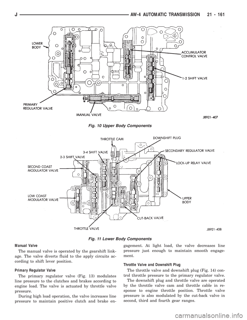
The manual valve, 1-2 shift valve, primary regula-
tor valve, accumulator control valve, check balls, so-
lenoids and oil strainers are located in the lower
body section (Fig. 10). The remaining control and
shift valves plus check balls and one additional oil
strainer are located in the upper body section (Fig.
11).
Fig. 8 Component Application Chart
Fig. 9 Two-Section Transmission Valve Body
21 - 160 AW-4 AUTOMATIC TRANSMISSIONJ
Page 1272 of 1784
Manual Valve
The manual valve is operated by the gearshift link-
age. The valve diverts fluid to the apply circuits ac-
cording to shift lever position.
Primary Regulator Valve
The primary regulator valve (Fig. 13) modulates
line pressure to the clutches and brakes according to
engine load. The valve is actuated by throttle valve
pressure.
During high load operation, the valve increases line
pressure to maintain positive clutch and brake en-gagement. At light load, the valve decreases line
pressure just enough to maintain smooth engage-
ment.
Throttle Valve and Downshift Plug
The throttle valve and downshift plug (Fig. 14) con-
trol throttle pressure to the primary regulator valve.
The downshift plug and throttle valve are operated
by the throttle valve cam and throttle cable in re-
sponse to engine throttle position. Throttle valve
pressure is also modulated by the cut-back valve in
second, third and fourth gear ranges.
Fig. 11 Lower Body Components
Fig. 10 Upper Body Components
JAW-4 AUTOMATIC TRANSMISSION 21 - 161
Page 1276 of 1784
De-energizing the solenoid causes the drain port to
close. Line pressure then moves the valve down ex-
posing the overdrive brake accumulator feed port for
the shift to fourth gear.
In the 1-2 or 3 gearshift lever positions, line pres-
sure from the 2-3 shift valve is applied to the lower
end of the 3-4 valve. This holds the valve upward,
closing off the overdrive brake feed port preventing a
shift into fourth gear.
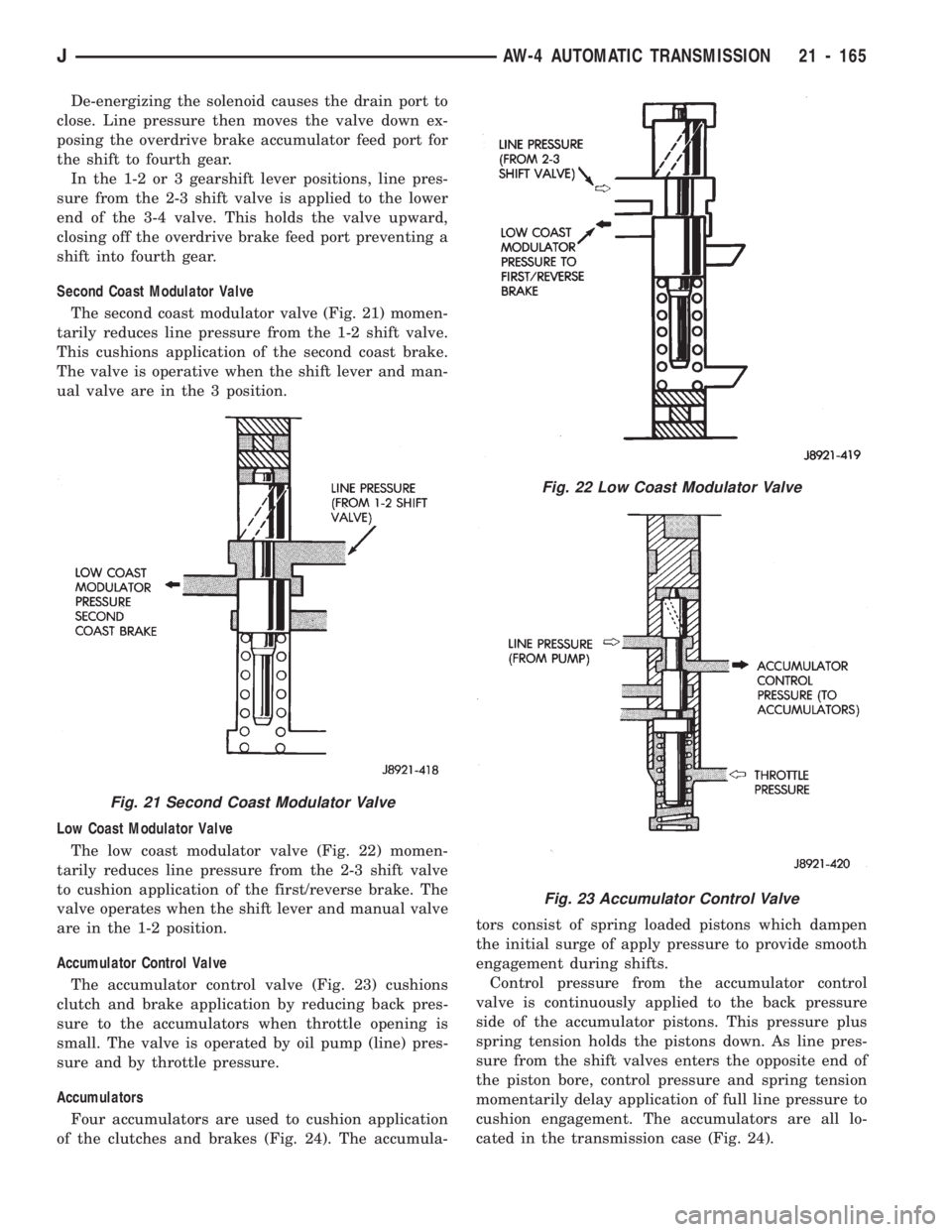
Second Coast Modulator Valve
The second coast modulator valve (Fig. 21) momen-
tarily reduces line pressure from the 1-2 shift valve.
This cushions application of the second coast brake.
The valve is operative when the shift lever and man-
ual valve are in the 3 position.
Low Coast Modulator Valve
The low coast modulator valve (Fig. 22) momen-
tarily reduces line pressure from the 2-3 shift valve
to cushion application of the first/reverse brake. The
valve operates when the shift lever and manual valve
are in the 1-2 position.
Accumulator Control Valve
The accumulator control valve (Fig. 23) cushions
clutch and brake application by reducing back pres-
sure to the accumulators when throttle opening is
small. The valve is operated by oil pump (line) pres-
sure and by throttle pressure.
Accumulators
Four accumulators are used to cushion application
of the clutches and brakes (Fig. 24). The accumula-tors consist of spring loaded pistons which dampen
the initial surge of apply pressure to provide smooth
engagement during shifts.
Control pressure from the accumulator control
valve is continuously applied to the back pressure
side of the accumulator pistons. This pressure plus
spring tension holds the pistons down. As line pres-
sure from the shift valves enters the opposite end of
the piston bore, control pressure and spring tension
momentarily delay application of full line pressure to
cushion engagement. The accumulators are all lo-
cated in the transmission case (Fig. 24).
Fig. 21 Second Coast Modulator Valve
Fig. 22 Low Coast Modulator Valve
Fig. 23 Accumulator Control Valve
JAW-4 AUTOMATIC TRANSMISSION 21 - 165
Page 1279 of 1784
(2) Verify transmission throttle cable operation.
Repair or replace cable if necessary.
(3) Check engine throttle operation. Operate accel-
erator pedal and observe injector throttle plate move-
ment. Adjust linkage if throttle plate does not reach
wide open position.
(4) Check transmission fluid level when fluid is at
normal operating temperature. Start engine. Shift
transmission through all gear ranges then back to
Neutral. Correct level is to Full or Add mark on dip-
stick with engine at curb idle speed.
(5) Check and adjust park/neutral position switch
if necessary.
(6) Check throttle position sensor adjustment and
operation. Adjust the sensor if necessary.
MANUAL SHIFTING TEST
(1) This test determines if problem is related to
mechanical or electrical component.
(2) Stop engine and disconnect transmission con-
trol module or module fuse.
(3) Road test vehicle. Shift transmission into each
gear range. Transmission should operate as follows:
²lock in Park
²back up in Reverse
²not move in Neutral
²provide first gear only with shift lever in 1-2 posi-
tion
²operate in third gear only with shift lever in 3 po-
sition
²operate in overdrive fourth gear in D position
(4) If transmission operates as described, proceed
to next step. However, if forward gear ranges were
difficult to distinguish (all feel the same), or vehicle
would not back up, refer to diagnosis charts. Do not
perform stall or time lag tests.
CAUTION: Do not overspeed the engine during the
next test step. Ease off the throttle and allow the
vehicle to slow before downshifting.
(5) Continue road test. Manually downshift trans-
mission from D to 3, and from 3 to 1-2 position. Then
manually upshift transmission through forward
ranges again.
(6) If transmission operation is OK, perform stall,
time lag and pressure tests. If transmission shifting
problem is encountered, refer to diagnosis charts.
(7) If a problem still exists, continue testing with
DRB II scan tool.
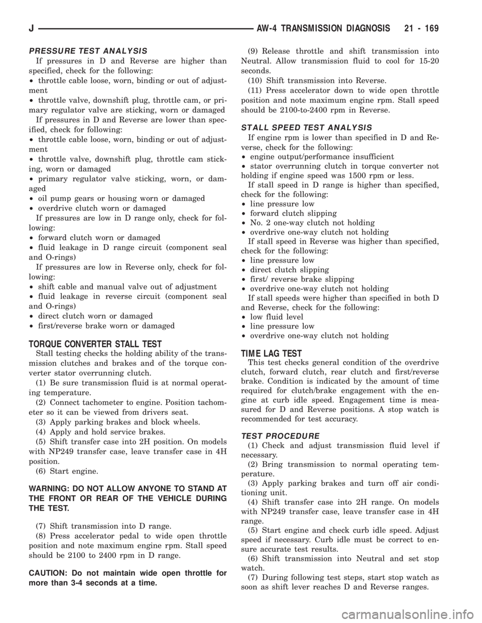
HYDRAULIC PRESSURE TEST
PRESSURE TEST PROCEDURE
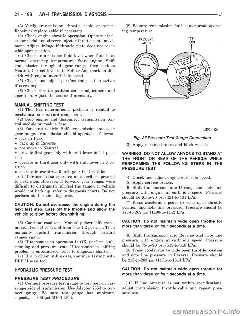
(1) Connect pressure test gauge to test port on pas-
senger side of transmission. Use Adapter 7554 to con-
nect gauge. Be sure test gauge has minimum
capacity of 300 psi (2100 kPa).(2) Be sure transmission fluid is at normal operat-
ing temperature.
(3) Apply parking brakes and block wheels.
WARNING: DO NOT ALLOW ANYONE TO STAND AT
THE FRONT OR REAR OF THE VEHICLE WHILE
PERFORMING THE FOLLOWING STEPS IN THE
PRESSURE TEST.
(4) Check and adjust engine curb idle speed.
(5) Apply service brakes.
(6) Shift transmission into D range and note line
pressure with engine at curb idle speed. Pressure
should be 61-to-70 psi (421-to-481 kPa).
(7) Press accelerator pedal to wide open throttle
position and note line pressure. Pressure should be
173-to-209 psi (1196-to-1442 kPa).
CAUTION: Do not maintain wide open throttle for
more than three or four seconds at a time.
(8) Shift transmission into Reverse and note line
pressure with engine at curb idle speed. Pressure
should be 75-to-90 psi (519-to-618 kPa).
(9) Press accelerator to wide open throttle position
and note line pressure in Reverse. Pressure should
be 213-to-263 psi (1471-to-1814 kPa).
CAUTION: Do not maintain wide open throttle for
more than three or four seconds at a time.
(10) If line pressure is not within specifications,
adjust transmission throttle cable and repeat pres-
sure test.
Fig. 27 Pressure Test Gauge Connection
21 - 168 AW-4 TRANSMISSION DIAGNOSISJ
Page 1280 of 1784
PRESSURE TEST ANALYSIS
If pressures in D and Reverse are higher than
specified, check for the following:
²throttle cable loose, worn, binding or out of adjust-
ment
²throttle valve, downshift plug, throttle cam, or pri-
mary regulator valve are sticking, worn or damaged
If pressures in D and Reverse are lower than spec-
ified, check for following:
²throttle cable loose, worn, binding or out of adjust-
ment
²throttle valve, downshift plug, throttle cam stick-
ing, worn or damaged
²primary regulator valve sticking, worn, or dam-
aged
²oil pump gears or housing worn or damaged
²overdrive clutch worn or damaged
If pressures are low in D range only, check for fol-
lowing:
²forward clutch worn or damaged
²fluid leakage in D range circuit (component seal
and O-rings)
If pressures are low in Reverse only, check for fol-
lowing:
²shift cable and manual valve out of adjustment
²fluid leakage in reverse circuit (component seal
and O-rings)
²direct clutch worn or damaged
²first/reverse brake worn or damaged
TORQUE CONVERTER STALL TEST
Stall testing checks the holding ability of the trans-
mission clutches and brakes and of the torque con-
verter stator overrunning clutch.
(1) Be sure transmission fluid is at normal operat-
ing temperature.
(2) Connect tachometer to engine. Position tachom-
eter so it can be viewed from drivers seat.
(3) Apply parking brakes and block wheels.
(4) Apply and hold service brakes.
(5) Shift transfer case into 2H position. On models
with NP249 transfer case, leave transfer case in 4H
position.
(6) Start engine.
WARNING: DO NOT ALLOW ANYONE TO STAND AT
THE FRONT OR REAR OF THE VEHICLE DURING
THE TEST.
(7) Shift transmission into D range.
(8) Press accelerator pedal to wide open throttle
position and note maximum engine rpm. Stall speed
should be 2100 to 2400 rpm in D range.
CAUTION: Do not maintain wide open throttle for
more than 3-4 seconds at a time.(9) Release throttle and shift transmission into
Neutral. Allow transmission fluid to cool for 15-20
seconds.
(10) Shift transmission into Reverse.
(11) Press accelerator down to wide open throttle
position and note maximum engine rpm. Stall speed
should be 2100-to-2400 rpm in Reverse.
STALL SPEED TEST ANALYSIS
If engine rpm is lower than specified in D and Re-
verse, check for the following:
²engine output/performance insufficient
²stator overrunning clutch in torque converter not
holding if engine speed was 1500 rpm or less.
If stall speed in D range is higher than specified,
check for the following:
²line pressure low
²forward clutch slipping
²No. 2 one-way clutch not holding
²overdrive one-way clutch not holding
If stall speed in Reverse was higher than specified,
check for the following:
²line pressure low
²direct clutch slipping
²first/ reverse brake slipping
²overdrive one-way clutch not holding
If stall speeds were higher than specified in both D
and Reverse, check for the following:
²low fluid level
²line pressure low
²overdrive one-way clutch not holding
TIME LAG TEST
This test checks general condition of the overdrive
clutch, forward clutch, rear clutch and first/reverse
brake. Condition is indicated by the amount of time
required for clutch/brake engagement with the en-
gine at curb idle speed. Engagement time is mea-
sured for D and Reverse positions. A stop watch is
recommended for test accuracy.
TEST PROCEDURE
(1) Check and adjust transmission fluid level if
necessary.
(2) Bring transmission to normal operating tem-
perature.
(3) Apply parking brakes and turn off air condi-
tioning unit.
(4) Shift transfer case into 2H range. On models
with NP249 transfer case, leave transfer case in 4H
range.
(5) Start engine and check curb idle speed. Adjust
speed if necessary. Curb idle must be correct to en-
sure accurate test results.
(6) Shift transmission into Neutral and set stop
watch.
(7) During following test steps, start stop watch as
soon as shift lever reaches D and Reverse ranges.
JAW-4 TRANSMISSION DIAGNOSIS 21 - 169
Page 1284 of 1784
AW-4 IN-VEHICLE SERVICE
INDEX
page page
Accumulator Pistons and Springs........... 179
Adapter Housing Seal Replacement.......... 182
Checking Fluid Level and Condition.......... 173
Manual Valve Shaft Seal Replacement....... 178
Park Interlock Cable Adjustment............ 186
Park Rod and Pawl Service................ 181
Park/Neutral Position Switch............... 173
Second Coast Brake Servo................ 181
Shift Cable Adjustment................... 186
Speed Sensor.......................... 182Speed Sensor RotorÐSpeedometer Drive Gear . 183
Throttle Position Sensor (TPS) Service....... 184
Transmission Control Module (TCM) Service . . . 173
Transmission Cooler Line Fittings........... 187
Transmission Cooler Service............... 187
Transmission Throttle Cable Adjustment....... 185
Transmission Throttle Cable Replacement..... 184
Transmission Valve Body Installation......... 177
Transmission Valve Body Removal.......... 176
Transmission Valve Body Solenoids.......... 175
CHECKING FLUID LEVEL AND CONDITION
Recommended fluid for AW-4 transmissions is Mo-
par Dexron IIE/Mercon. Mopar Dexron II may be
used if Mercon fluid is not readily available.
CHECKING FLUID LEVEL
(1) Be sure transmission fluid is at normal operat-
ing temperature. Normal operating temperature is
reached after approximately 15 miles (25 km) of op-
eration.
(2) Position vehicle on level surface. This is impor-
tant for an accurate fluid level check.
(3) Shift transmission through all gear ranges and
back to Park.
(4) Apply parking brakes.
(5) Verify that transmission is in Park.
(6) Wipe off dipstick handle to prevent dirt from
entering fill tube. Then remove dipstick and check
fluid level and condition.
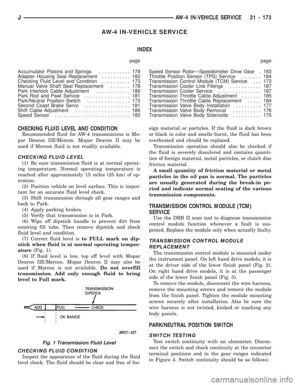
(7) Correct fluid level isto FULL mark on dip-
stick when fluid is at normal operating temper-
ature(Fig. 1).
(8) If fluid level is low, top off level with Mopar
Dexron IIE/Mercon. Mopar Dexron II may also be
used if Mercon is not available.Do not overfill
transmission. Add only enough fluid to bring
level to Full mark.
CHECKING FLUID CONDITION
Inspect the appearance of the fluid during the fluid
level check. The fluid should be clear and free of for-eign material or particles. If the fluid is dark brown
or black in color and smells burnt, the fluid has been
overheated and should be replaced.
Transmission operation should also be checked if
the fluid is severely discolored and contains quanti-
ties of foreign material, metal particles, or clutch disc
friction material.
A small quantity of friction material or metal
particles in the oil pan is normal. The particles
are usually generated during the break-in pe-
riod and indicate normal seating of the various
transmission components.
TRANSMISSION CONTROL MODULE (TCM)
SERVICE
Use the DRB II scan tool to diagnose transmission
control module function whenever a fault is sus-
pected. Replace the module only when actually faulty.
TRANSMISSION CONTROL MODULE
REPLACEMENT
The transmission control module is mounted under
the instrument panel. On left hand drive models, it is
at the driver side of the lower finish panel (Fig. 2).
On right hand drive models, it is at the passenger
side of the lower finish panel (Fig. 3).
To remove the module, disconnect the wire harness,
remove the mounting screws and remove the module
from the finish panel. Tighten the module mounting
screws securely after installation. Also be sure the
wire harness is not twisted, kinked or touching any
body panels.
PARK/NEUTRAL POSITION SWITCH
SWITCH TESTING
Test switch continuity with an ohmmeter. Discon-
nect the switch and check continuity at the connector
terminal positions and in the gear ranges indicated
in Figure 3. Switch continuity should be as follows:Fig. 1 Transmission Fluid Level
JAW-4 IN-VEHICLE SERVICE 21 - 173
Page 1378 of 1784
outer diameter is 47.2 mm (1.858 in.) and inside di-
ameter is 28.1 mm (1.106 in.).
(66) Lubricate and install replacement O-ring on
oil pump body.
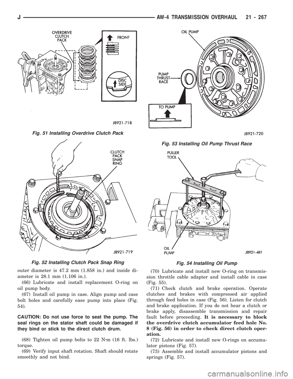
(67) Install oil pump in case. Align pump and case
bolt holes and carefully ease pump into place (Fig.
54).
CAUTION: Do not use force to seat the pump. The
seal rings on the stator shaft could be damaged if
they bind or stick to the direct clutch drum.
(68) Tighten oil pump bolts to 22 Nzm (16 ft. lbs.)
torque.
(69) Verify input shaft rotation. Shaft should rotate
smoothly and not bind.(70) Lubricate and install new O-ring on transmis-
sion throttle cable adapter and install cable in case
(Fig. 55).
(71) Check clutch and brake operation. Operate
clutches and brakes with compressed air applied
through feed holes in case (Fig. 56). Listen for clutch
and brake application. If you do not hear a clutch or
brake apply, disassemble transmission and repair
fault before proceeding.It is necessary to block
the overdrive clutch accumulator feed hole No.
8 (Fig. 56) in order to check direct clutch oper-
ation.
(72) Lubricate and install new O-rings on accumu-
lator pistons (Fig. 57).
(73) Assemble and install accumulator pistons and
springs (Fig. 57).
Fig. 53 Installing Oil Pump Thrust Race
Fig. 54 Installing Oil Pump
Fig. 51 Installing Overdrive Clutch Pack
Fig. 52 Installing Clutch Pack Snap Ring
JAW-4 TRANSMISSION OVERHAUL 21 - 267
Page 1444 of 1784
WHEELS AND TIRES
CONTENTS
page page
SPECIFICATIONS....................... 11
TIRES................................. 1VEHICLE VIBRATION..................... 9
WHEELS............................... 6
TIRES
INDEX
page page
Cleaning of Tires.......................... 2
General Information........................ 1
Pressure Gauges......................... 2
Repairing Leaks.......................... 3
Replacement Tires........................ 2Rotation................................ 3
Tire Inflation Pressures..................... 2
Tire Noise or Vibration..................... 4
Tire Wear Patterns........................ 4
Tread Wear Indicators...................... 3
GENERAL INFORMATION
Tires are designed for each specific vehicle. They
provide the best overall performance for normal op-
eration. The ride and handling characteristics match
the vehicle's requirements. With proper care they
will give excellent reliability, traction, skid resis-
tance, and tread life. These tires have specific load
carrying capacities. When correctly inflated, they
will operate properly.
Tires used in cool climates, and with light loads
will have a longer life than tires used in hot climates
with heavy loads. Abrasive road surfaces will accel-
erate tire wear.
Driving habits have more effect on tire life than
any other factor. Careful drivers will obtain much
greater mileage than careless drivers.
Driving habits that shorten the life of any tire;
²Rapid acceleration and deceleration
²Severe application of brakes
²High-speed driving
²Taking turns at excessive speeds
²Striking curbs and other obstacles
It is very important to follow the tire rotation in-
terval
IDENTIFICATION
Tire type, size, aspect ratio and speed rating are
encoded in the letters and numbers imprinted on the
side wall of the tire. Refer to the chart to decipher
the tire identification code (Fig. 1).
Performance tires will have a speed rating letter
after the aspect ratio number. The speed rating isnot always printed on the tire sidewall. The letterS
indicates that the tire is speed rated up to 112 mph.
²Qup to 100 mph
²Tup to 118 mph
²Uup to 124 mph
²Hup to 130 mph
²Vup to 149 mph
²Zmore than 149 mph (consult the tire manufac-
turer for the specific speed rating)
An All Season type tire will have eitherM+S,M
&SorMÐS(indicating mud and snow traction) im-
printed on the side wall.
RADIAL-PLY TIRES
Radial-ply tires improve handling, tread life, ride
quality and decrease rolling resistance.
Radial-ply tires must always be used in sets of
four. Under no circumstances should they be used on
the front only. They may be mixed with temporary
spare tires when necessary, but reduced speeds are
recommended.
Radial-ply tires have the same load-carrying capac-
ity as other types of tires of the same size. They use
the same recommended inflation pressures.
SPARE TIRE (TEMPORARY)
The compact spare tire is designed for emergency
use only. The original tire should be repaired and re-
installed at the first opportunity. Refer to Owner's
Manual for complete details.
JWHEELS AND TIRES 22 - 1