1994 JEEP CHEROKEE brakes
[x] Cancel search: brakesPage 981 of 1784
energized). This is done to compensate for the re-
duced flow through injector caused by the lowered
voltage.
BRAKE SWITCHÐPCM INPUT
When the brake light switch is activated, the pow-
ertrain control module (PCM) receives an input indi-
cating that the brakes are being applied. After
receiving this input, the PCM maintains idle speed
to a scheduled rpm through control of the idle air
control (IAC) motor. The brake switch input is also
used to operate the speed control system.
CAMSHAFT POSITION SENSORÐPCM INPUT
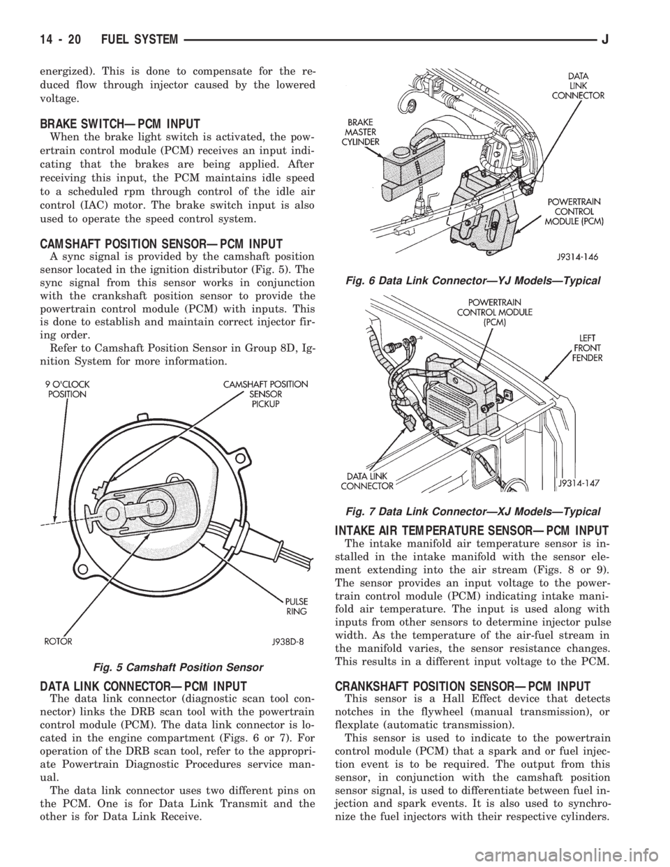
A sync signal is provided by the camshaft position
sensor located in the ignition distributor (Fig. 5). The
sync signal from this sensor works in conjunction
with the crankshaft position sensor to provide the
powertrain control module (PCM) with inputs. This
is done to establish and maintain correct injector fir-
ing order.
Refer to Camshaft Position Sensor in Group 8D, Ig-
nition System for more information.
DATA LINK CONNECTORÐPCM INPUT
The data link connector (diagnostic scan tool con-
nector) links the DRB scan tool with the powertrain
control module (PCM). The data link connector is lo-
cated in the engine compartment (Figs. 6 or 7). For
operation of the DRB scan tool, refer to the appropri-
ate Powertrain Diagnostic Procedures service man-
ual.
The data link connector uses two different pins on
the PCM. One is for Data Link Transmit and the
other is for Data Link Receive.
INTAKE AIR TEMPERATURE SENSORÐPCM INPUT
The intake manifold air temperature sensor is in-
stalled in the intake manifold with the sensor ele-
ment extending into the air stream (Figs. 8 or 9).
The sensor provides an input voltage to the power-
train control module (PCM) indicating intake mani-
fold air temperature. The input is used along with
inputs from other sensors to determine injector pulse
width. As the temperature of the air-fuel stream in
the manifold varies, the sensor resistance changes.
This results in a different input voltage to the PCM.
CRANKSHAFT POSITION SENSORÐPCM INPUT
This sensor is a Hall Effect device that detects
notches in the flywheel (manual transmission), or
flexplate (automatic transmission).
This sensor is used to indicate to the powertrain
control module (PCM) that a spark and or fuel injec-
tion event is to be required. The output from this
sensor, in conjunction with the camshaft position
sensor signal, is used to differentiate between fuel in-
jection and spark events. It is also used to synchro-
nize the fuel injectors with their respective cylinders.
Fig. 5 Camshaft Position Sensor
Fig. 6 Data Link ConnectorÐYJ ModelsÐTypical
Fig. 7 Data Link ConnectorÐXJ ModelsÐTypical
14 - 20 FUEL SYSTEMJ
Page 1015 of 1784
MULTI-PORT FUEL INJECTION (MFI)ÐCOMPONENT REMOVAL/INSTALLATION
INDEX
page page
Accelerator Pedal and Throttle Cable......... 54
Air Cleaner Housing...................... 54
Air Conditioning (A/C) Clutch Relay........... 54
Air Filter............................... 54
Automatic Shut Down (ASD) Relay........... 54
Brake Switch............................ 54
Camshaft Position Sensor.................. 54
Crankshaft Position Sensor................. 55
Engine Coolant Temperature Sensor.......... 55
Fuel Filter.............................. 55
Fuel Injector............................ 55
Fuel Pump Module....................... 56
Fuel Pump Relay........................ 56
Fuel Rail Assembly....................... 56
Fuel System Pressure Release Procedure...... 56
Fuel Tank Pressure Relief/Rollover Valve...... 56
Fuel Tanks............................. 56Fuel Tubes/Lines/Hoses and Clamps.......... 56
Idle Air Control (IAC) Motor................. 56
Ignition Coil............................. 57
Intake Air Temperature Sensor.............. 54
Intake Manifold.......................... 57
Manifold Absolute Pressure (MAP) Sensor..... 57
Oxygen (O2S) Sensor..................... 57
Park Neutral Switch....................... 58
Power Steering Pressure SwitchÐ2.5L
Engine Only........................... 58
Powertrain Control Module (PCM)............ 58
Quick-Connect Fittings..................... 59
Throttle Body............................ 59
Throttle Position Sensor (TPS).............. 59
Torque Converter Clutch Relay.............. 60
Vehicle Speed Sensor..................... 60
ACCELERATOR PEDAL AND THROTTLE CABLE
Refer to the Accelerator Pedal and Throttle Cable
section of this group for removal/installation proce-
dures.
AIR CONDITIONING (A/C) CLUTCH RELAY
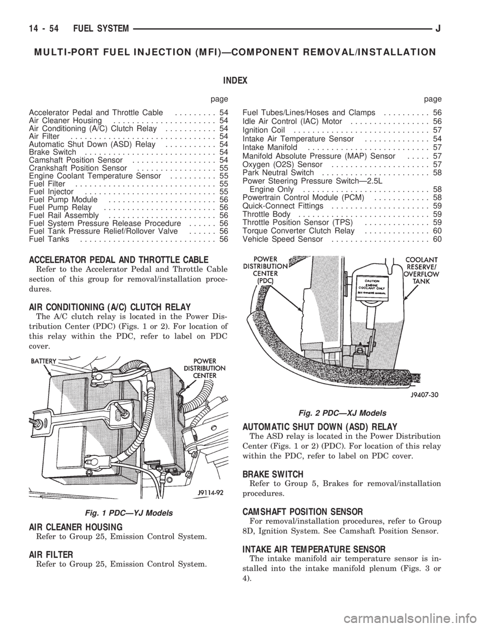
The A/C clutch relay is located in the Power Dis-
tribution Center (PDC) (Figs. 1 or 2). For location of
this relay within the PDC, refer to label on PDC
cover.
AIR CLEANER HOUSING
Refer to Group 25, Emission Control System.
AIR FILTER
Refer to Group 25, Emission Control System.
AUTOMATIC SHUT DOWN (ASD) RELAY
The ASD relay is located in the Power Distribution
Center (Figs. 1 or 2) (PDC). For location of this relay
within the PDC, refer to label on PDC cover.
BRAKE SWITCH
Refer to Group 5, Brakes for removal/installation
procedures.
CAMSHAFT POSITION SENSOR
For removal/installation procedures, refer to Group
8D, Ignition System. See Camshaft Position Sensor.
INTAKE AIR TEMPERATURE SENSOR
The intake manifold air temperature sensor is in-
stalled into the intake manifold plenum (Figs. 3 or
4).
Fig. 1 PDCÐYJ Models
Fig. 2 PDCÐXJ Models
14 - 54 FUEL SYSTEMJ
Page 1026 of 1784
SERVICE DIAGNOSIS/PROCEDURES
INDEX
page page
Runout................................. 4
Unbalance............................... 3Universal Joint Angle Measurement............ 4
Vibration................................ 3
VIBRATION
Tires that are out-of-round or wheels that are un-
balanced will cause a low frequency vibration. Refer
to Group 22, Wheels and Tires for additional infor-
mation.
Brake drums that are unbalanced will cause a
harsh, low frequency vibration. Refer to Group 5,
Brakes for additional information.
Driveline vibration can also result from loose or
damaged engine mounts. Refer to Group 21, Trans-
missions for additional information.
Propeller shaft vibration will increase as the vehi-
cle speed is increased. A vibration that occurs within
a specific speed range is not caused by propeller
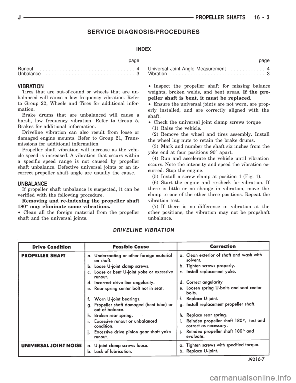
shaft unbalance. Defective universal joints or an in-
correct propeller shaft angle are usually the cause.
UNBALANCE
If propeller shaft unbalance is suspected, it can be
verified with the following procedure.
Removing and re-indexing the propeller shaft
180É may eliminate some vibrations.
²Clean all the foreign material from the propeller
shaft and the universal joints.²Inspect the propeller shaft for missing balance
weights, broken welds, and bent areas.If the pro-
peller shaft is bent, it must be replaced.
²Ensure the universal joints are not worn, are prop-
erly installed, and are correctly aligned with the
shaft.
²Check the universal joint clamp screws torque
(1) Raise the vehicle.
(2) Remove the wheel and tires assembly. Install
the wheel lug nuts to retain the brake drums.
(3) Mark and number the shaft six inches from the
yoke end at four positions 90É apart.
(4) Run and accelerate the vehicle until vibration
occurs. Note the intensity and speed the vibration oc-
curred. Stop the engine.
(5) Install a screw clamp at position 1 (Fig. 1).
(6) Start the engine and re-check for vibration. If
there is little or no change in vibration, move the
clamp to one of the other three positions. Repeat the
vibration test.
(7) If there is no difference in vibration at the
other positions, the vibration may not be propshaft
unbalance.
DRIVELINE VIBRATION
JPROPELLER SHAFTS 16 - 3
Page 1180 of 1784
30RH/32RH TRANSMISSION DIAGNOSIS
INDEX
page page
Air Pressure Test........................ 73
Analyzing the Road Test................... 70
Converter Housing Leak Diagnosis........... 73
Converter Stall Test...................... 72
Diagnosis Guides and Charts............... 76
Fluid Level and Condition.................. 69Gearshift Linkage........................ 70
General Information....................... 69
Hydraulic Pressure Test................... 71
Preliminary Diagnosis..................... 69
Road Test.............................. 70
Transmission Throttle Valve Cable Adjustment . . 70
GENERAL INFORMATION
Automatic transmission problems are generally the
result of:
²poor engine performance
²incorrect fluid level
²incorrect cable/linkage adjustment
²incorrect band adjustment
²incorrect hydraulic control pressure adjustments
²hydraulic component malfunctions
²mechanical component malfunctions.
Begin diagnosis by checking the easily accessible
items such as fluid level, fluid condition and control
linkage adjustment. A road test will determine if fur-
ther diagnosis is necessary.
Procedures outlined in this section should be per-
formed in the following sequence to realize the most
accurate results:
²Preliminary diagnosis
²Check fluid Level and condition
²Check control linkage Adjustment
²Road test
²Stall test
²Hydraulic pressure test
²Air pressure tests
²Leak Tests
²Analyze test results and consult diagnosis charts
PRELIMINARY DIAGNOSIS
Two basic procedures are required. One procedure
for vehicles that are driveable and an alternate pro-
cedure for disabled vehicles (will not back up or
move forward).
Vehicle Is Driveable
(1) Check fluid level and condition.
(2) Adjust throttle cable and gearshift linkage if
complaint was based on delayed, erratic, or harsh
shifts.
(3) Road test vehicle and note transmission operat-
ing characteristics.
(4) Perform stall test if complaint is based on slug-
gish, low speed acceleration or abnormal throttle
opening needed to maintain normal speeds with
properly tuned engine.
(5) Perform hydraulic pressure tests.(6) Perform air pressure test to check clutch-band
operation.
Vehicle Is Disabled
(1) Check fluid level and condition.
(2) Check for broken, disconnected throttle link-
age.
(3) Check for cracked, leaking cooler lines, or
loose, missing pressure port plugs.
(4) Raise vehicle, start engine, shift transmission
into gear and note following:
(a) If propeller shafts turn but wheels do not,
problem is with differential or axle shafts.
(b) If propeller shafts do not turn and transmis-
sion is noisy, stop engine. Remove oil pan, and
check for debris. If pan is clear, remove transmis-
sion and check for damaged drive plate, converter,
oil pump or input shaft.
(c) If propeller shafts do not turn and transmis-
sion is not noisy, perform hydraulic pressure test to
determine if problem is a hydraulic or mechanical.
FLUID LEVEL AND CONDITION
(1) Position vehicle on level surface. This is impor-
tant in obtaining an accurate fluid level check.
(2) To avoid false readings, which could produce
under or over fill condition, do not check level until
fluid is at normal operating temperature.
(3) Shift transmission into Neutral.
(4) Apply parking brakes.
(5) Operate engine at curb idle speed.
WARNING: WHEN PERFORMING UNDERHOOD OP-
ERATIONS WITH THE ENGINE RUNNING, KEEP
YOUR HANDS WELL AWAY FROM HOT OR ROTAT-
ING ENGINE COMPONENTS. DO NOT WEAR
LOOSE ARTICLES OF CLOTHING WHICH COULD
BECOME ENTANGLED IN ENGINE COMPONENTS
OR ACCESSORIES.
(6) Clean dipstick filler cap and tube before remov-
ing dipstick.
(7) Remove dipstick and inspect fluid level.
²Correct level is to FULL mark
²Acceptable level is between ADD and FULL marks
J30RH/32RH TRANSMISSION DIAGNOSIS 21 - 69
Page 1183 of 1784
(5) Line pressure should be 54-60 psi (372-414
kPa) with throttle lever forward and gradually in-
crease to 90-96 psi (620-662 kPa) as lever is moved
rearward.
Test Three-Transmission In D Range
This test checks pressure regulation and con-
dition of the front and rear clutch circuits.
Both test gauges are required for this test.
(1) Connect one test gauge to line pressure port
and other gauge to front servo pressure port (Fig. 4).
Either gauge can be used at either port.
(2) Start and run engine at 1600 rpm.
(3) Move selector lever two detents rearward from
full forward position. This is D range.
(4) Read pressures on both gauges as transmission
throttle lever is moved from full forward to full rear-
ward position.
(5) Line pressure should be 54-60 psi (372-414
kPa) with throttle lever forward and gradually in-
crease as lever is moved rearward.
(6) Front servo is pressurized only in D range and
should be same as line pressure within 3 psi (21
kPa), up to downshift point.
Test Four-Transmission In Reverse
This test checks pump output, pressure regu-
lation and the front clutch and rear servo cir-
cuits. Use 300 psi Pressure Test Gauge C-3293
for this test.
(1) Connect pressure test gauge to rear servo port
(Fig. 5).
(2) Start and run engine at 1600 rpm for test.
(3) Move valve body selector lever four detents
rearward from full forward position. This is Reverse
range.
(4) Move throttle lever all way forward then all the
way rearward and note gauge readings.
(5) Pressure should be 145 - 175 psi (1000-1207
kPa) with lever forward and increase to 230 - 280 psi
(1586-1931 kPa) as lever is moved rearward.
Test Five-Governor Pressure
This test checks governor operation by mea-
suring governor pressure response to changes
in engine speed. It is usually not necessary to
check governor operation unless shift speeds
are incorrect or if the transmission will not
shift up or down. Use 100 psi Pressure Test
Gauge C-3292 for this test.
(1) Connect test gauge to governor pressure port
(Figs. 5 and 6).
(2) Move selector lever to D range.
(3) Apply service brakes. Start and run engine at
curb idle speed and note pressure. At idle and with
wheels stopped, pressure should be zero to 1-1/2 psi
maximum. If pressure exceeds this figure, governor
valve or weights are sticking open.(4) Slowly increase engine speed and observe
speedometer and pressure test gauge. Governor pres-
sure should increase in proportion to vehicle speed
(approximately 1 psi for every 1 mph shown on
speedometer).
(5) Governor pressure rise should be smooth and
drop back to 0 to 1-1/2 psi when throttle is closed
and wheels are stopped.
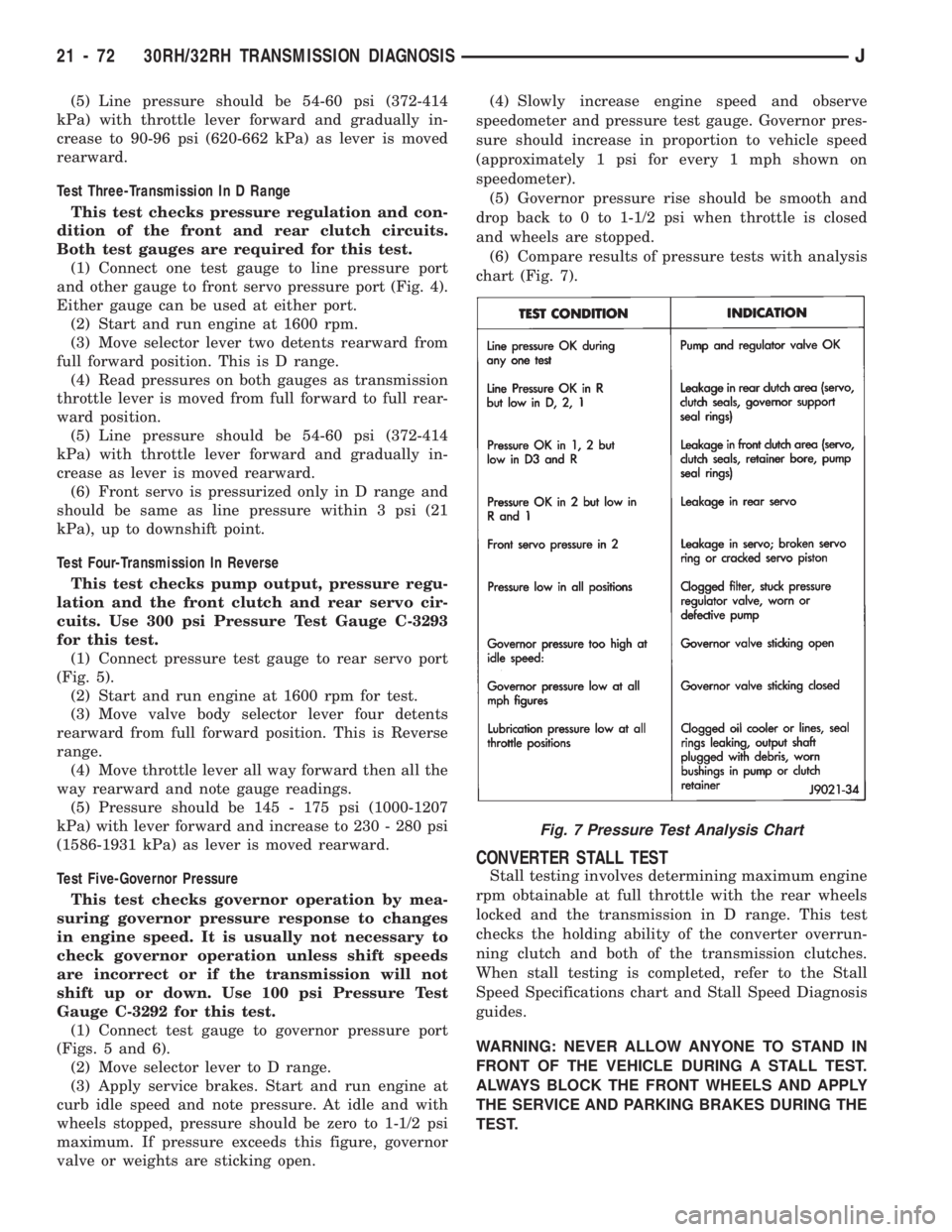
(6) Compare results of pressure tests with analysis
chart (Fig. 7).
CONVERTER STALL TEST
Stall testing involves determining maximum engine
rpm obtainable at full throttle with the rear wheels
locked and the transmission in D range. This test
checks the holding ability of the converter overrun-
ning clutch and both of the transmission clutches.
When stall testing is completed, refer to the Stall
Speed Specifications chart and Stall Speed Diagnosis
guides.
WARNING: NEVER ALLOW ANYONE TO STAND IN
FRONT OF THE VEHICLE DURING A STALL TEST.
ALWAYS BLOCK THE FRONT WHEELS AND APPLY
THE SERVICE AND PARKING BRAKES DURING THE
TEST.
Fig. 7 Pressure Test Analysis Chart
21 - 72 30RH/32RH TRANSMISSION DIAGNOSISJ
Page 1184 of 1784
STALL TEST PROCEDURE
(1) Connect tachometer to engine.
(2) Check and adjust transmission fluid level.
(3) Start and run engine until transmission fluid
reaches normal operating temperature.
(4) Block front wheels.
(5) Fully apply service and parking brakes.
(6) Open throttle completely for no more than five
seconds and record maximum engine rpm registered
on tachometer.
CAUTION: Stall testing causes a rapid increase in
transmission fluid temperature. Do not hold the
throttle open any longer than five seconds. If more
than one stall test is required, run the engine at
1000 rpm with the transmission in Neutral for at
least 20 seconds to cool the fluid.
(7) If engine speed exceeds maximum shown in
stall speed chart, release accelerator immediately.
This indicates that transmission clutch slippage is
occurring.
(8) Shift transmission into Neutral. Run engine for
20 seconds to cool fluid. Then stop engine, shift
transmission into Park and release brakes.
(9) Stall speeds should be in 1700-2000 rpm range.
(10) Refer to Stall Test Diagnosis.
STALL TEST DIAGNOSIS
Stall Speed Too High
If the stall speed exceeds specifications by more
than 200 rpm, transmission clutch slippage is indi-
cated.
Stall Speed Too Low
Low stall speeds with a properly tuned engine in-
dicate a torque converter overrunning clutch prob-
lem. The condition should be confirmed by road
testing prior to converter replacement.
The converter overrunning clutch is slipping when
stall speeds are 250 to 350 rpm below specified min-
imum. And when the vehicle operates properly at
highway speeds but has poor low speed acceleration.
Stall Speed Normal
If stall speeds are normal but abnormal throttle
opening is required to maintain highway speeds, the
converter overrunning clutch is seized and the torque
converter must be replaced.
Converter Noise During Test
A whining noise caused by fluid flow is normal
during a stall test. However, loud metallic noises in-
dicate a damaged converter. To confirm that noise is
originating from the converter, operate the vehicle at
light throttle in Drive and Neutral on a hoist and lis-
ten for noise coming from the converter housing.
AIR PRESSURE TEST
Air pressure testing can be used to check clutch
and band operation with the transmission either in
the vehicle, or on the work bench as a final check af-
ter overhaul.
Air pressure testing requires that the oil pan and
valve body be removed from the transmission.
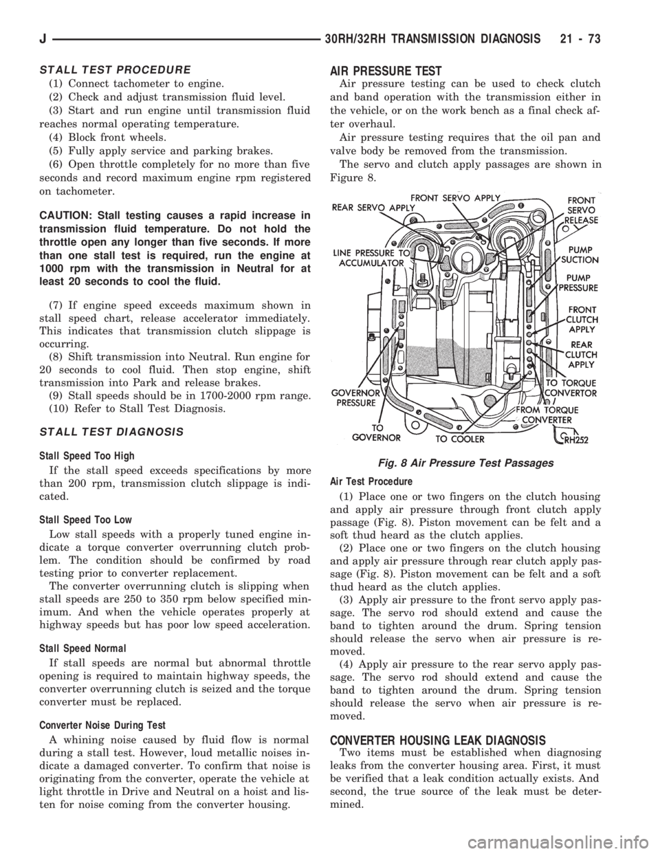
The servo and clutch apply passages are shown in
Figure 8.
Air Test Procedure
(1) Place one or two fingers on the clutch housing
and apply air pressure through front clutch apply
passage (Fig. 8). Piston movement can be felt and a
soft thud heard as the clutch applies.
(2) Place one or two fingers on the clutch housing
and apply air pressure through rear clutch apply pas-
sage (Fig. 8). Piston movement can be felt and a soft
thud heard as the clutch applies.
(3) Apply air pressure to the front servo apply pas-
sage. The servo rod should extend and cause the
band to tighten around the drum. Spring tension
should release the servo when air pressure is re-
moved.
(4) Apply air pressure to the rear servo apply pas-
sage. The servo rod should extend and cause the
band to tighten around the drum. Spring tension
should release the servo when air pressure is re-
moved.
CONVERTER HOUSING LEAK DIAGNOSIS
Two items must be established when diagnosing
leaks from the converter housing area. First, it must
be verified that a leak condition actually exists. And
second, the true source of the leak must be deter-
mined.
Fig. 8 Air Pressure Test Passages
J30RH/32RH TRANSMISSION DIAGNOSIS 21 - 73
Page 1207 of 1784
30RH/32RH IN-VEHICLE SERVICE
INDEX
page page
Checking Fluid Level and Condition........... 96
Front Band Adjustment.................... 99
Gearshift Linkage Adjustment (YJ)............ 96
Governor and Park Gear Service............ 101
Oil Filter Replacement.................... 100
Park Interlock Cable Adjustment (XJ)......... 97
Park Lock Component Replacement......... 102
Park/Neutral Position Switch Service......... 103
Rear Band Adjustment.................... 99
Recommended Fluid...................... 96
Servicing Transmission Cooler Lines and Fittings. 106
Shift Cable Adjustment (XJ)................ 97
Speedometer Service.................... 103
Transmission Cooler Flow Testing........... 106
Transmission Cooler Reverse Flushing....... 105
Transmission Throttle Cable Adjustment (XJ/YJ) . 98
Valve Body Installation................... 101
Valve Body Removal..................... 100
Valve Body Service...................... 100
RECOMMENDED FLUID
The recommended and preferred fluid for 30RH/
32RH transmissions is Mopar ATF Plus, Type 7176.
Mopar Dexron II is acceptable but should only be
used when ATF Plus is not available.
Transmission fluid capacity is approximately 17
pints (7.9 liters). This is the approximate amount of
fluid required to fill the transmission and torque con-
verter after overhaul.
CHECKING FLUID LEVEL AND CONDITION
(1) Position vehicle on flat, level surface. This is
important in obtaining an accurate fluid level check.
(2) To avoid false readings, which could produce
under or over fill condition, do not check level until
fluid is at normal operating temperature.
(3) Shift transmission into Neutral.
(4) Apply parking brakes.
(5) Operate engine at curb idle speed.
WARNING: WHEN PERFORMING UNDERHOOD OP-
ERATIONS WITH THE ENGINE RUNNING, KEEP
YOUR HANDS WELL AWAY FROM HOT OR ROTAT-
ING ENGINE COMPONENTS. DO NOT WEAR
LOOSE ARTICLES OF CLOTHING WHICH COULD
BECOME ENTANGLED IN ENGINE COMPONENTS
OR ACCESSORIES.
(6) Shift transmission through all gear ranges and
back to Neutral (leave engine running).
(7) Clean exterior of dipstick cap and fill tube be-
fore removing transmission dipstick.
(8) Remove dipstick and inspect fluid level.
²Correct level is to FULL mark
²Acceptable level is between ADD and FULL marks
(9) Check fluid condition. Fluid should be dark to
light red in color and free of dirt or debris.
(10) If fluid is discolored or smells burned but
transmission operation was OK, check cooler flow,
flush cooler and lines and change fluid and filter.
Then road test again to confirm proper operation.(11) If fluid is black or dark brown, burned/turned
to sludge, contains large quantities of metal or fric-
tion material particles, transmission will need over-
haul. Especially if problems were evident during
road test and preliminary diagnosis. Fluid cooler
should also be flow tested and flushed if necessary.
GEARSHIFT LINKAGE ADJUSTMENT (YJ)
(1) Check linkage adjustment by starting engine in
Park and Neutral.
(2) Adjustment is OK if engine starts only in park
and Neutral. Adjustment is incorrect if engine starts
in one but not both positions.
(3) If engine starts in any position other than Park
or Neutral, or if engine will not start at all, park/
neutral position switch may be faulty.
(4) Shift transmission into Park.
(5) Raise vehicle.
(6) Check condition of shift rods, bellcrank, bell-
crank brackets and linkage bushings/grommets (Fig.
1). Tighten, repair, replace worn, damaged parts. Do
not attempt adjustment if linkage components are
worn or damaged.
(7) Loosen shift rod trunnion lock bolt or nut. Be
sure upper shift rod slides freely in trunnion (Fig. 1).
Also be sure shift rods and bellcrank rotate freely
and do not bind at any point.
(8) Verify that manual lever is in Park detent
(Fig. 1). Move lever all the way rearward to be sure
it is in Park.
(9) Check for positive engagement of park lock by
attempting to rotate propeller shaft. Shaft will not
turn when park pawl is engaged.
(10) Adjust shift rod trunnion to a obtain free pin
fit in bellcrank arm and tighten trunnion lock bolt or
nut. Prevent shift rod from turning while tightening
bolt or nut. Gearshift linkage lash must be elimi-
nated to obtain proper adjustment. Eliminate lash by
pulling downward on shift rod and pressing upward
on bellcrank.
21 - 96 30RH/32RH IN-VEHICLE SERVICEJ
Page 1269 of 1784
net complete one revolution. Sensor signals are sent
to the transmission control module.
The park/neutral position switch is mounted on the
valve body manual shaft. The switch signals shift
linkage and manual valve position to the transmis-
sion control module through an interconnecting har-
ness. The switch prevents engine starting in all gears
other than Park or Neutral.
The brake switch is in circuit with the torque con-
verter clutch solenoid. The switch disengages the
converter clutch whenever the brakes are applied.
The switch is mounted on the brake pedal bracket
and signals the transmission control module when
the pedal is pressed or released.
TORQUE CONVERTER
A four element torque converter is used for all ap-
plications. The converter consists of the front cover
and pump, stator, turbine, and an electronic modu-
lated converter clutch mechanism.
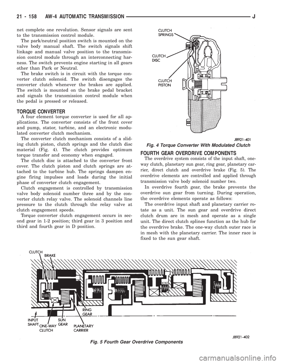
The converter clutch mechanism consists of a slid-
ing clutch piston, clutch springs and the clutch disc
material (Fig. 4). The clutch provides optimum
torque transfer and economy when engaged.
The clutch disc is attached to the converter front
cover. The clutch piston and clutch springs are at-
tached to the turbine hub. The springs dampen en-
gine firing impulses and loads during the initial
phase of converter clutch engagement.
Clutch engagement is controlled by transmission
valve body solenoid number three and by the con-
verter clutch relay valve. The solenoid channels line
pressure to the clutch through the relay valve at
clutch engagement speeds.
Torque converter clutch engagement occurs in sec-
ond gear in 1-2 position; third gear in 3 position and
third and fourth gear in D position.
FOURTH GEAR OVERDRIVE COMPONENTS
The overdrive system consists of the input shaft, one-
way clutch, planetary sun gear, ring gear, planetary car-
rier, direct clutch and overdrive brake (Fig. 5). The
overdrive elements are controlled and applied through
transmission valve body solenoid number two.
In overdrive fourth gear, the brake prevents the
overdrive sun gear from turning. During operation,
the overdrive elements operate as follows:
The overdrive input shaft and planetary carrier ro-
tate as a unit. The sun gear and overdrive direct
clutch drum are in mesh and operate as a single
unit. The direct clutch splines function as the hub for
the overdrive brake. The one-way clutch outer race is
in mesh with the planetary carrier. The inner race is
fixed to the sun gear shaft.
Fig. 5 Fourth Gear Overdrive Components
Fig. 4 Torque Converter With Modulated Clutch
21 - 158 AW-4 AUTOMATIC TRANSMISSIONJ