1994 JEEP CHEROKEE brakes
[x] Cancel search: brakesPage 35 of 1784
(6) Inspect the disc brake caliper dust boot for cor-
rect installation, damage/tears and indications of
brake fluid leakage. Inspect the bushings and pins
for corrosion, tears and a binding condition.
(7) Pull the rear wheel cylinder dust boot back to
expose the wheel cylinder housing and inspect for
fluid leaks. Inspect the pistons and cylinder bores for
proper appearance.
(8) Inspect the brake differential warning valve
and housing for indications of leakage, kinked hoses
and loose fittings.
PARK BRAKE
(1) As applicable, engage the park brake lever or
pedal and then release it.
(2) If the park brake is functioning normally, test
it for smooth operation and vehicle-holding capabil-
ity.
(3) Inspect the park brake cables for kinks, fraying
and a binding condition.
(4) With the park brake released, the rear wheels
should rotate without restriction. Adjust the park
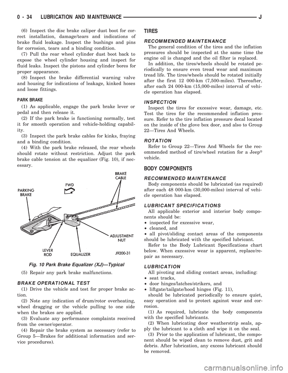
brake cable tension at the equalizer (Fig. 10), if nec-
essary.
(5) Repair any park brake malfunctions.
BRAKE OPERATIONAL TEST
(1) Drive the vehicle and test for proper brake ac-
tion.
(2) Note any indication of drum/rotor overheating,
wheel dragging or the vehicle pulling to one side
when the brakes are applied.
(3) Evaluate any performance complaints received
from the owner/operator.
(4) Repair the brake system as necessary (refer to
Group 5ÐBrakes for additional information and ser-
vice procedures).
TIRES
RECOMMENDED MAINTENANCE
The general condition of the tires and the inflation
pressures should be inspected at the same time the
engine oil is changed and the oil filter is replaced.
In addition, the tires/wheels should be rotated pe-
riodically to ensure even tread wear and maximum
tread life. The tires/wheels should be rotated initially
after the first 12 000-km (7,500-miles). Thereafter,
after each 24 000-km (15,000-miles) interval of vehi-
cle operation has elapsed.
INSPECTION
Inspect the tires for excessive wear, damage, etc.
Test the tires for the recommended inflation pres-
sure. Refer to the tire inflation pressure decal located
on the inside of the glove box door, and also to Group
22ÐTires And Wheels.
ROTATION
Refer to Group 22ÐTires And Wheels for the rec-
ommended method of tire/wheel rotation for a Jeept
vehicle.
BODY COMPONENTS
RECOMMENDED MAINTENANCE
Body components should be lubricated (as required)
after each 48 000-km (30,000-miles) interval of vehi-
cle operation has elapsed.
LUBRICANT SPECIFICATIONS
All applicable exterior and interior body compo-
nents should be:
²inspected for excessive wear,
²cleaned, and
²all pivot/sliding contact areas of the components
should be lubricated with the specified lubricant.
Refer to the Body Lubricant Specifications chart
below. When excessive wear is apparent, replace/re-
pair as necessary.
LUBRICATION
All pivoting and sliding contact areas, including:
²seat tracks,
²door hinges/latches/strikers, and
²liftgate/tailgate/hood hinges (Fig. 11),
should be lubricated periodically to ensure quiet,
easy operation and to protect against wear and cor-
rosion.
(1) As required, lubricate the body components
with the specified lubricants.
(2) When lubricating door weatherstrip seals, ap-
ply the lubricant to a cloth and wipe it on the seal.
(3) Prior to the application of lubricant, the compo-
nent should be wiped clean to remove dust, grit and
debris. After lubrication, any excess lubricant should
be removed.
Fig. 10 Park Brake Equalizer (XJ)ÐTypical
0 - 34 LUBRICATION AND MAINTENANCEJ
Page 40 of 1784
The shocks absorbers dampen jounce and rebound
of the vehicle over various road conditions. The top of
the shock absorbers are bolted to the frame. The bot-
tom of the shocks are bolted to the axle bracket.
The stabilizer bar is used to minimize vehicle front
sway during turns. The spring steel bar helps to con-
trol the vehicle body in relationship to the suspen-
sion. The bar extends across the front underside of
the chassis and connects to the frame rails. Links are
connected from the bar to the axle brackets. Stabi-
lizer bar mounts are isolated by rubber bushings.
The track bar is used to minimize front axle side-
to-side movement. The track bar is attached to a
frame rail bracket and the axle bracket.
The bar uses bushings at both ends.
FRONT DRIVE AXLE
It is not necessary to remove the complete axle
from the vehicle for routine differential service. If
the differential housing or axle shaft tubes are dam-
aged, the complete axle assembly can be removed
and serviced.
For complete drive axle assembly removal and in-
stallation refer to Drive Axle Assembly Replacement
in this Group.
The removable cover provides for servicing without
removing axle from vehicle.
The integral type housing, hypoid gear design has
the centerline of the pinion set above the centerline
of the ring gear.
The Model 30 axle has the assembly part number
and gear ratio listed on a tag. The tag is attached to
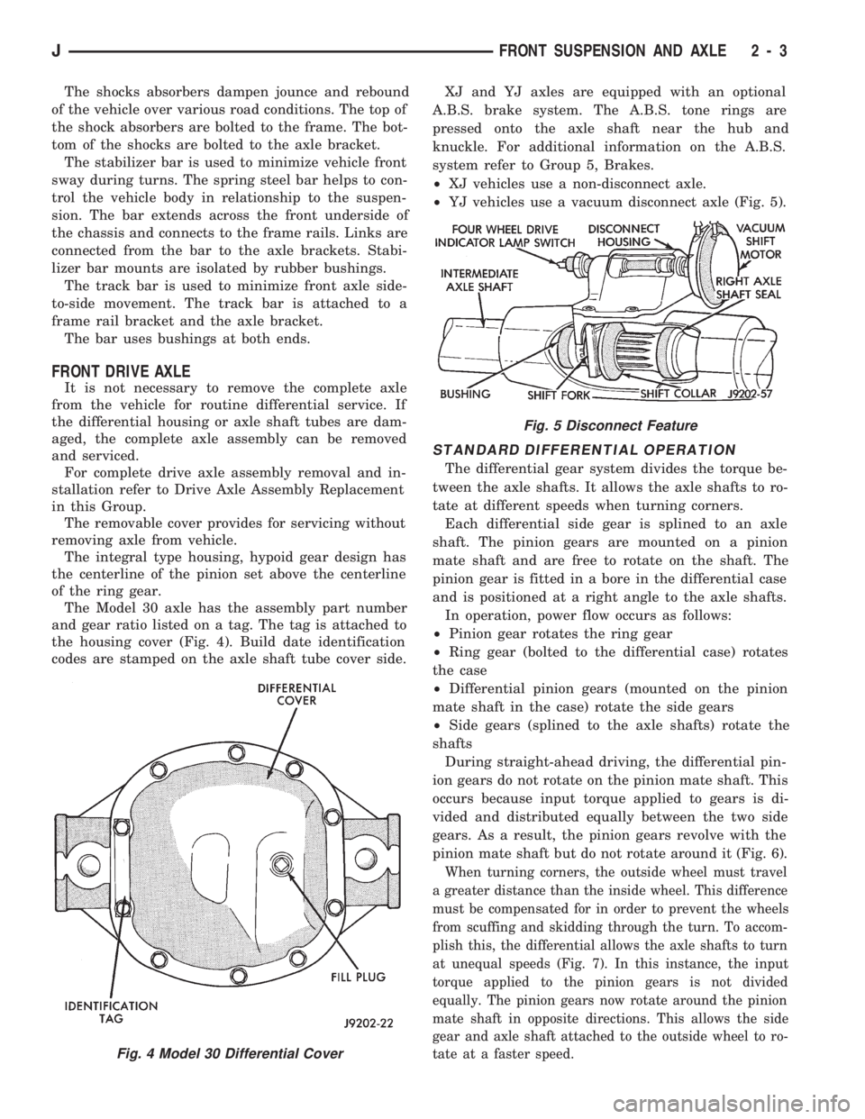
the housing cover (Fig. 4). Build date identification
codes are stamped on the axle shaft tube cover side.XJ and YJ axles are equipped with an optional
A.B.S. brake system. The A.B.S. tone rings are
pressed onto the axle shaft near the hub and
knuckle. For additional information on the A.B.S.
system refer to Group 5, Brakes.
²XJ vehicles use a non-disconnect axle.
²YJ vehicles use a vacuum disconnect axle (Fig. 5).
STANDARD DIFFERENTIAL OPERATION
The differential gear system divides the torque be-
tween the axle shafts. It allows the axle shafts to ro-
tate at different speeds when turning corners.
Each differential side gear is splined to an axle
shaft. The pinion gears are mounted on a pinion
mate shaft and are free to rotate on the shaft. The
pinion gear is fitted in a bore in the differential case
and is positioned at a right angle to the axle shafts.
In operation, power flow occurs as follows:
²Pinion gear rotates the ring gear
²Ring gear (bolted to the differential case) rotates
the case
²Differential pinion gears (mounted on the pinion
mate shaft in the case) rotate the side gears
²Side gears (splined to the axle shafts) rotate the
shafts
During straight-ahead driving, the differential pin-
ion gears do not rotate on the pinion mate shaft. This
occurs because input torque applied to gears is di-
vided and distributed equally between the two side
gears. As a result, the pinion gears revolve with the
pinion mate shaft but do not rotate around it (Fig. 6).
When turning corners, the outside wheel must travel
a greater distance than the inside wheel. This difference
must be compensated for in order to prevent the wheels
from scuffing and skidding through the turn. To accom-
plish this, the differential allows the axle shafts to turn
at unequal speeds (Fig. 7). In this instance, the input
torque applied to the pinion gears is not divided
equally. The pinion gears now rotate around the pinion
mate shaft in opposite directions. This allows the side
gear and axle shaft attached to the outside wheel to ro-
tate at a faster speed.
Fig. 4 Model 30 Differential Cover
Fig. 5 Disconnect Feature
JFRONT SUSPENSION AND AXLE 2 - 3
Page 57 of 1784
MODEL 30 AXLE AND TUBE AXLE (2WD)
INDEX
page page
Axle Bushing Replacement................. 32
Axle Shaft Ð Cardan U-Joint................ 25
Axle Specifications....................... 46
Backlash and Contact Pattern Analysis........ 44
Cleaning/Inspection....................... 35
Differential and Pinion Measurement.......... 38
Differential Assembly...................... 36
Differential Disassembly.................... 34
Differential Installation..................... 43
Differential Removal...................... 32
Differential Shim Pack Measurement and Adjustment.42
Drive Axle Assembly ReplacementÐXJ Vehicles . 21
Drive Axle Assembly ReplacementÐYJ Vehicles . 21Final Assembly.......................... 44
Hub Bearing and Axle Shaft................ 24
Information............................. 20
Inner Axle Shaft Oil Seal Replacement........ 33
Lubricant Change........................ 22
Lubricant Specifications.................... 20
Pinion Gear Assembly/Installation............ 40
Pinion Gear Depth Information.............. 37
Pinion Removal/Disassembly................ 34
Pinion Seal Replacement.................. 23
Steering Knuckle and Ball Studs............. 30
Vacuum Disconnect Axle Ð YJ Vehicles....... 26
INFORMATION
The housing for Model 30 front axles consists of an
iron center casting (differential housing) with axle
shaft tubes extending from either side. The tubes are
pressed into and welded to the differential housing to
form a one-piece axle housing.
The integral type housing, hypoid gear design has
the centerline of the pinion set above the centerline
of the ring gear.
The axle has a fitting for a vent hose used to re-
lieve internal pressure caused by lubricant vaporiza-
tion and internal expansion.
The axles are equipped with semi-floating axle
shafts, meaning that loads are supported by the hub
bearings. The axle shafts are retained by nuts at the
hub bearings. The hub bearings are bolted to the
steering knuckle at the outboard end of the axle tube
yoke. The hub bearings are serviced as an assembly.
The axles are equipped with ABS brake sensors.
The sensors are attached to the knuckle assemblies
and tone rings are pressed on the axle shaft.Use
care when removing axle shafts as NOT to dam-
age the tone wheel or the sensor.
The stamped steel cover provides a means for in-
spection and servicing the differential.
The Model 30 axle has the assembly part number
and gear ratio listed on a tag. The tag is attached to
the housing cover. Build date identification codes are
stamped on the axle shaft tube cover side.
The differential case is a one-piece design. The dif-
ferential pinion mate shaft is retained with a roll
pin. Differential bearing preload and ring gear back-
lash is adjusted by the use of shims (select thick-
ness). The shims are located between the differential
bearing cones and case. Pinion bearing preload is set
and maintained by the use of collapsible spacer.
PINION GEAR DEPTH MEASUREMENT WITH
PINION GAUGE SET 6774, Pinion Block 6733 and
Dial Indicator C-3339 is performed when;²Axle/differential housing is being replaced
²Original pinion depth shim pack is lost or mis-
placed
²Replacing the differential case
²Original differential bearing shim pack is lost or
misplaced
COMMAND-TRACÐYJ VEHICLES
The Command-Trac system is a vacuum disconnect
axle. The system has a two-piece axle shaft coupled
together by a shift collar. For two-wheel drive oper-
ation, the vacuum motor and shift fork disengages
the axle shaft splines. For four-wheel drive opera-
tion, the vacuum motor and shift fork engages the
splines.
SELEC-TRACÐXJ VEHICLES
The Selec-Trac system is a non-disconnect axle.
Shifting from two-wheel to four-wheel drive is at the
transfer case.
For XJ vehicles equipped withSelec-Tracand
ABS brake system, refer to Group 5ÐBrakes for ad-
ditional service information.
LUBRICANT SPECIFICATIONS
Multi-purpose, hypoid gear lubricant should be
used for Model 30 axles. The lubricant should have
MIL-L-2105C and API GL 5 quality specifications.
MOPARtHypoid Gear Lubricant conforms to both of
these specifications.
²The factory fill for the Model 30 axle is SAE 75W
gear lubricant.Do not use heavier weight lubri-
cant, this will cause axle engagement difficulties.
²The factory installed lubricant quantity for the
NON-DISCONNECT TYPE AXLE is 5061 fluid oz..
²The factory installed lubricant quantity for the
VACUUM-DISCONNECT TYPE AXLE is 5661 fluid
oz..
2 - 20 FRONT SUSPENSION AND AXLEJ
Page 58 of 1784
Refer to Group 0, Lubrication and Maintenance for
additional information regarding temperature range,
viscosity and fluid level.
CAUTION: If the axle is submerged in water, the lu-
bricant must be replaced immediately to avoid the
possibility of premature axle failure.
DRIVE AXLE ASSEMBLY REPLACEMENTÐXJ
VEHICLES
REMOVAL
(1) Raise the vehicle and position support stands
under the frame rails slightly in behind the lower
suspension arm frame brackets.
(2) Remove the front wheels.
(3) Remove the brake components and ABS brake
sensor (if equipped). Refer to Group 5ÐBrakes.
(4) On 4WD vehicles, disconnect the axle vent
hose.
(5) On 4WD vehicles, mark the drive shaft yoke
and axle pinion yoke for alignment reference. Discon-
nect the drive shaft from the axle.
(6) Disconnect the stabilizer bar link at the axle
bracket.
(7) Disconnect the shock absorbers from axle
bracket.
(8) Disconnect the track bar from the axle bracket.
(9) Disconnect the tie rod and drag link from the
steering knuckle. Disconnect the steering dampener
from the axle bracket.
(10) Support the axle with a hydraulic jack under
the differential.
(11) Disconnect the upper and lower suspension
arms from the axle bracket.
(12) Lower the jack enough to remove the axle.
The coil springs will drop with the axle.
(13) Remove the coil springs from the axle bracket.
INSTALLATION
CAUTION: All suspension components that use rub-
ber bushings should be tightened with the vehicle
at the ride height. It is important to have the
springs supporting the weight of the vehicle when
the fasteners are torqued. If the springs are not at
their normal ride position, vehicle ride comfort
could be affected along with premature rubber
bushing wear. Rubber bushings must never be lu-
bricated.
(1) Install the springs and retainer clip. Tighten
the retainer bolts to 21 Nzm (16 ft. lbs.) torque.
(2) Support the axle on a hydraulic jack under the
differential. Position the axle under the vehicle.
(3) Raise the axle with a floor jack and align it
with the spring pads.(4) Position the upper and lower suspension arm at
the axle bracket. Install bolts and nuts finger
tighten.
(5) Connect the track bar to the axle bracket and
install the bolt.Do not tighten at this time.
It is important that the springs support the
weight of the vehicle when the track bar is con-
nected. If the springs are not at their usual po-
sition, the vehicle ride comfort could be affected.
(6) Install the shock absorber and tighten the bolt
to 19 Nzm (14 ft. lbs.) torque.
(7) Install the stabilizer bar link to the axle
bracket. Tighten the nut to 95 Nzm (70 ft. lbs.)
torque.
(8) Install the drag link and tie rod to the steering
knuckles and tighten the nuts to 47 Nzm (35 ft. lbs.)
torque. Install the steering dampener to the axle
bracket and tighten the nut to 75 Nzm (55 ft. lbs.)
torque.
(9) Install the brake components and ABS brake
sensor (if equipped). Refer to Group 5ÐBrakes.
(10) On 4WD vehicles, connect the vent hose to the
tube fitting.
(11) On 4WD vehicles, align the reference marks
and connect the drive shaft to the axle yoke. Tighten
the U-joint clamp bolts to 19 Nzm (14 ft. lbs.) torque.
(12) Check differential lubricant and add if neces-
sary.
(13) Install the wheel and tire assemblies.
(14) Remove the supports and lower the vehicle.
(15) Tighten the upper suspension arm nuts to 75
Nzm (55 ft. lbs.) torque. Tighten the lower suspension
arm nuts to 115 Nzm (85 ft. lbs.) torque.
(16) Tighten the track bar bolt at the axle bracket
to 100 Nzm (74 ft. lbs.) torque.
(17) Check the front wheel alignment.
DRIVE AXLE ASSEMBLY REPLACEMENTÐYJ
VEHICLES
REMOVAL
(1) Raise the vehicle and position support stands
under the frame rails slightly behind the spring
frame brackets.
(2) Remove the front wheels.
(3) Remove the brake components and ABS brake
sensor (if equipped). Refer to Group 5ÐBrakes.
(4) Disconnect the axle vent hose and axle shift
motor vacuum harness.
(5) Mark the drive shaft yoke and axle pinion yoke
for alignment reference. Disconnect the drive shaft
from the axle.
(6) Disconnect the stabilizer bar link at the axle
bracket.
(7) Disconnect the shock absorbers from axle
bracket.
(8) Disconnect the track bar from the axle bracket.
JFRONT SUSPENSION AND AXLE 2 - 21
Page 59 of 1784
(9) Disconnect the tie rod from the steering
knuckle. Disconnect the steering dampener from the
axle bracket.
(10) Support the axle with a hydraulic jack under
the differential. Raise the axle just enough to relieve
the axle weight from the springs.
(11) Remove the spring U-bolts from the plate
brackets.
(12) Loosen BUT DO NOT REMOVE the bolts that
attach the spring rear pivot at the frame rail brack-
ets. This will allow the springs to pivot without bind-
ing on the bushings.
(13) Disconnect shackle from the springs and lower
the springs to the surface.
(14) Lower the jack enough to remove the axle.
INSTALLATION
CAUTION: All suspension components that use rub-
ber bushings should be tightened with the vehicle
at the normal height. It is important to have the
springs supporting the weight of the vehicle when
the fasteners are torqued. If the springs are not at
their normal ride position, vehicle ride comfort
could be affected along with premature rubber
bushing wear. Rubber bushings must never be lu-
bricated.
(1) Support the axle on a hydraulic jack under the
differential. Position the axle under the vehicle.
(2) Raise the springs and install the spring shackle
bolts.Do not tighten at this time.
(3) Lower the axle and align the spring center
bolts with the locating holes in the axle pads and
plate brackets.
(4) Install the spring U-bolts through the plate
brackets and tighten to 122 Nzm (90 ft. lbs.) torque.
(5) Connect the track bar to the axle bracket and
install the bolt.Do not tighten at this time.
It is important that the springs support the
weight of the vehicle when the track bar is con-
nected. If the springs are not at their usual po-
sition, the vehicle ride comfort could be affected.
(6) Install the shock absorber and tighten the nut
to 61 Nzm (45 ft. lbs.) torque.
(7) Install the stabilizer bar link to the axle
bracket. Tighten the nut to 61 Nzm (45 ft. lbs.)
torque.
(8) Install the tie rod to the steering knuckles and
tighten the nuts to 47 Nzm (35 ft. lbs.) torque. Install
the steering dampener to the axle bracket and
tighten the bolt to 75 Nzm (55 ft. lbs.) torque.
(9) Install the brake components and ABS brake
sensor (if equipped). Refer to Group 5ÐBrakes.
(10) Connect the vent hose to the tube fitting and
axle shift motor vacuum harness.(11) Align the reference marks and connect the
drive shaft to the axle yoke. Tighten the U-joint
clamp bolts to 19 Nzm (14 ft. lbs.) torque.
(12) Check differential lubricant and add if neces-
sary.
(13) Install the wheel and tire assemblies.
(14) Remove the supports and lower the vehicle.
(15) Tighten the spring rear pivot bolt/nut to 142
Nzm (105 ft. lbs.) torque. Tighten the spring shackle
bolt/nut to 135 Nzm (100 ft. lbs.) torque.
(16) Tighten the track bar nut at the axle bracket
to 100 Nzm (74 ft. lbs.) torque.
(17) Check the front wheel alignment.
LUBRICANT CHANGE
The gear lubricant will drain quicker if the vehicle
has been recently driven.
(1) Raise and support the vehicle.
(2) Remove the lubricant fill hole plug from the
differential housing cover.
(3) Remove the differential housing cover and
drain the lubricant from the housing.
(4) Clean the housing cavity with a flushing oil,
light engine oil or lint free cloth.Do not use water,
steam, kerosene or gasoline for cleaning.
(5) Remove the sealant from the housing and cover
surfaces. Use solvent to clean the mating surfaces.
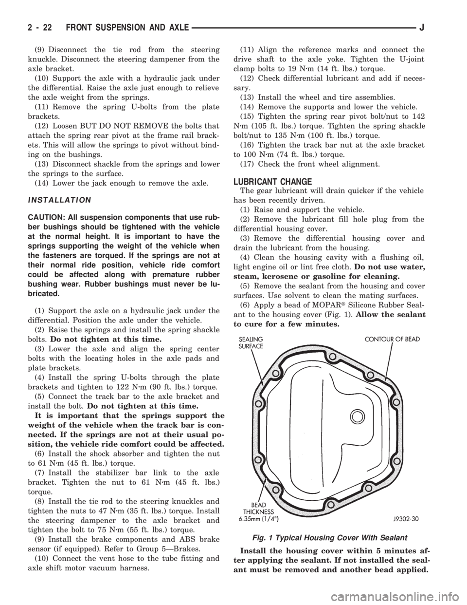
(6) Apply a bead of MOPARtSilicone Rubber Seal-
ant to the housing cover (Fig. 1).Allow the sealant
to cure for a few minutes.
Install the housing cover within 5 minutes af-
ter applying the sealant. If not installed the seal-
ant must be removed and another bead applied.
Fig. 1 Typical Housing Cover With Sealant
2 - 22 FRONT SUSPENSION AND AXLEJ
Page 60 of 1784
(7) Install the cover and any identification tag.
Tighten the cover bolts in a criss-cross pattern to 41
Nzm (30 ft. lbs.) torque.
(8) Refill the differential with MOPARtHypoid
Gear Lubricant within 13 mm (1/2 in.) below the fill
plug hole.
(9) Install the fill hole plug and lower the vehicle.
PINION SEAL REPLACEMENT
CAUTION: The following procedures must be used
so the correct pinion bearing preload torque is re-
tained. If this procedure is not followed, the result
can be premature failure of the rear axle.
REMOVAL
(1) Raise and support the vehicle.
(2) Remove wheel and tire assemblies.
(3) Mark the propeller shaft yoke and pinion yoke
for installation alignment reference.
(4) Remove the propeller shaft from the yoke.
(5) Rotate the pinion gear three or four times.
Make sure brakes are not dragging during this
procedure.
(6) Measure the amount of torque (in Newton-
meters or inch-pounds) necessary to rotate the pinion
gear with a torque wrench. Note the torque for in-
stallation reference.It must be known to properly
adjust the pinion gear bearing preload torque
after seal installation.
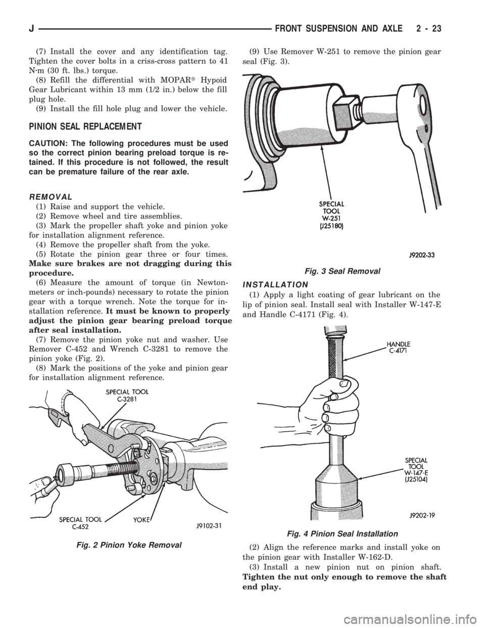
(7) Remove the pinion yoke nut and washer. Use
Remover C-452 and Wrench C-3281 to remove the
pinion yoke (Fig. 2).
(8) Mark the positions of the yoke and pinion gear
for installation alignment reference.(9) Use Remover W-251 to remove the pinion gear
seal (Fig. 3).
INSTALLATION
(1) Apply a light coating of gear lubricant on the
lip of pinion seal. Install seal with Installer W-147-E
and Handle C-4171 (Fig. 4).
(2) Align the reference marks and install yoke on
the pinion gear with Installer W-162-D.
(3) Install a new pinion nut on pinion shaft.
Tighten the nut only enough to remove the shaft
end play.
Fig. 2 Pinion Yoke Removal
Fig. 3 Seal Removal
Fig. 4 Pinion Seal Installation
JFRONT SUSPENSION AND AXLE 2 - 23
Page 61 of 1784
CAUTION: Never loosen the pinion gear nut to de-
crease the pinion gear bearing preload torque. If the
specified preload torque is exceeded, a new col-
lapsible spacer must be installed. The torque se-
quence will have to be repeated.
(4) Install a socket and inch-pound torque wrench
on the pinion nut.
(5) Rotate the shaft with the torque wrench and
note the torque.
Required preload torque is the amount re-
corded during removal plus an additional 0.56
Nzm (5 in. lbs.).
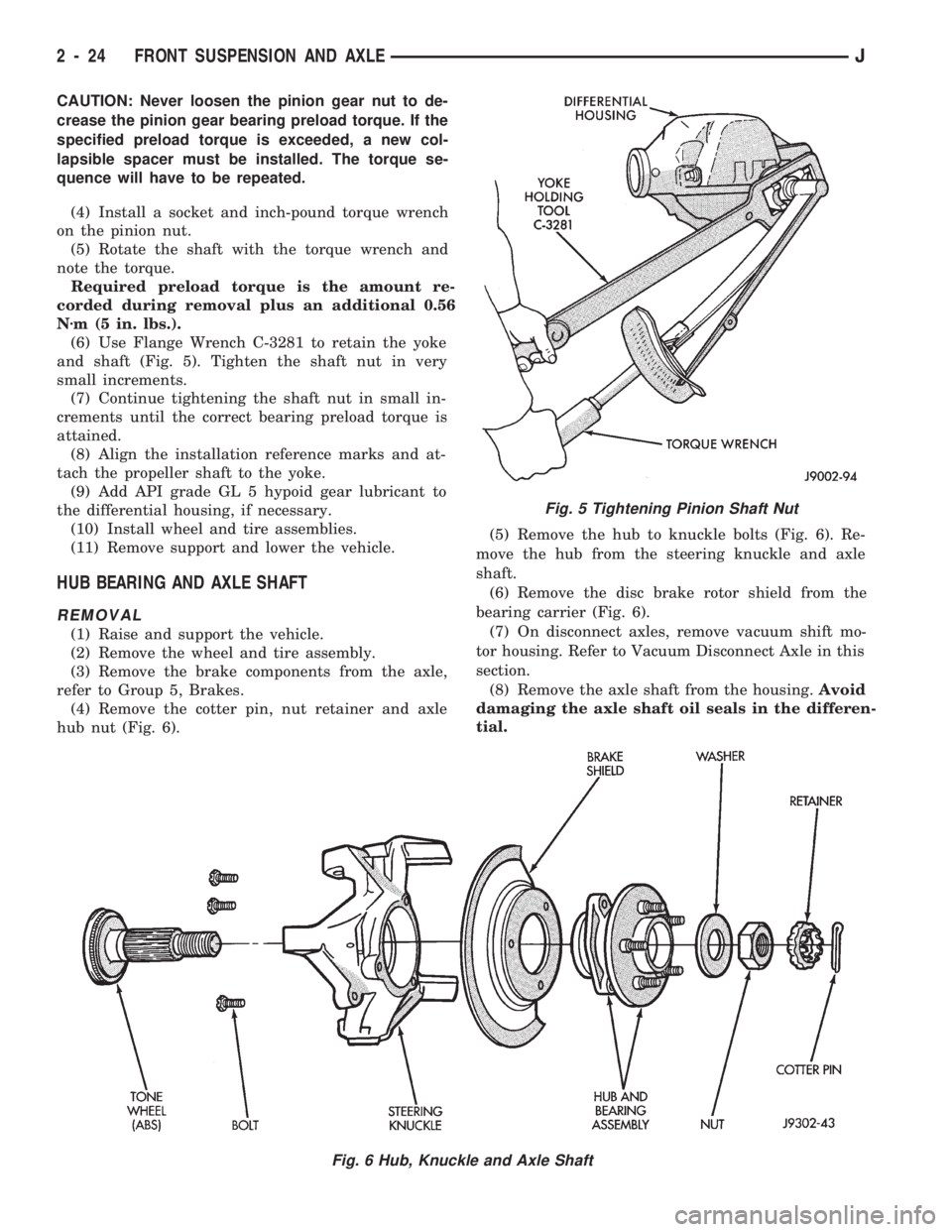
(6) Use Flange Wrench C-3281 to retain the yoke
and shaft (Fig. 5). Tighten the shaft nut in very
small increments.
(7) Continue tightening the shaft nut in small in-
crements until the correct bearing preload torque is
attained.
(8) Align the installation reference marks and at-
tach the propeller shaft to the yoke.
(9) Add API grade GL 5 hypoid gear lubricant to
the differential housing, if necessary.
(10) Install wheel and tire assemblies.
(11) Remove support and lower the vehicle.
HUB BEARING AND AXLE SHAFT
REMOVAL
(1) Raise and support the vehicle.
(2) Remove the wheel and tire assembly.
(3) Remove the brake components from the axle,
refer to Group 5, Brakes.
(4) Remove the cotter pin, nut retainer and axle
hub nut (Fig. 6).(5) Remove the hub to knuckle bolts (Fig. 6). Re-
move the hub from the steering knuckle and axle
shaft.
(6) Remove the disc brake rotor shield from the
bearing carrier (Fig. 6).
(7) On disconnect axles, remove vacuum shift mo-
tor housing. Refer to Vacuum Disconnect Axle in this
section.
(8) Remove the axle shaft from the housing.Avoid
damaging the axle shaft oil seals in the differen-
tial.
Fig. 5 Tightening Pinion Shaft Nut
Fig. 6 Hub, Knuckle and Axle Shaft
2 - 24 FRONT SUSPENSION AND AXLEJ
Page 62 of 1784
INSTALLATION
(1) Thoroughly clean the axle shaft (Fig. 6) and ap-
ply a thin film of Mopar Wheel Bearing Grease to
the shaft splines, seal contact surface, hub bore.
(2) Install the axle shaft into the housing and dif-
ferential side gears. Avoid damaging the axle shaft
oil seals in the differential.
(3) Install the hub bearing and brake dust shield
to the knuckle.
(4) Install the hub to knuckle bolts and tighten to
102 Nzm (75 ft. lbs.) torque.
(5) Install the hub washer and nut. Tighten the
hub nut to 237 Nzm (175 ft. lbs.) torque. Install the
nut retainer and a new cotter pin (Fig. 6).
(6) Install the brake components, refer to Group 5,
Brakes.
(7) Install the wheel and tire assembly.
(8) Remove support and lower the vehicle.
AXLE SHAFTÐ CARDAN U-JOINT
DISASSEMBLY
Single cardan U-joints are not serviceable. If defec-
tive, they must be replaced as a unit. If the bearings,
seals, spider or bearing caps are damaged or worn,
replace the complete U-joint.
CAUTION: Clamp only the forged portion of the
yoke in the vise. Also, to avoid distorting the yoke,
do not over tighten the vise jaws.
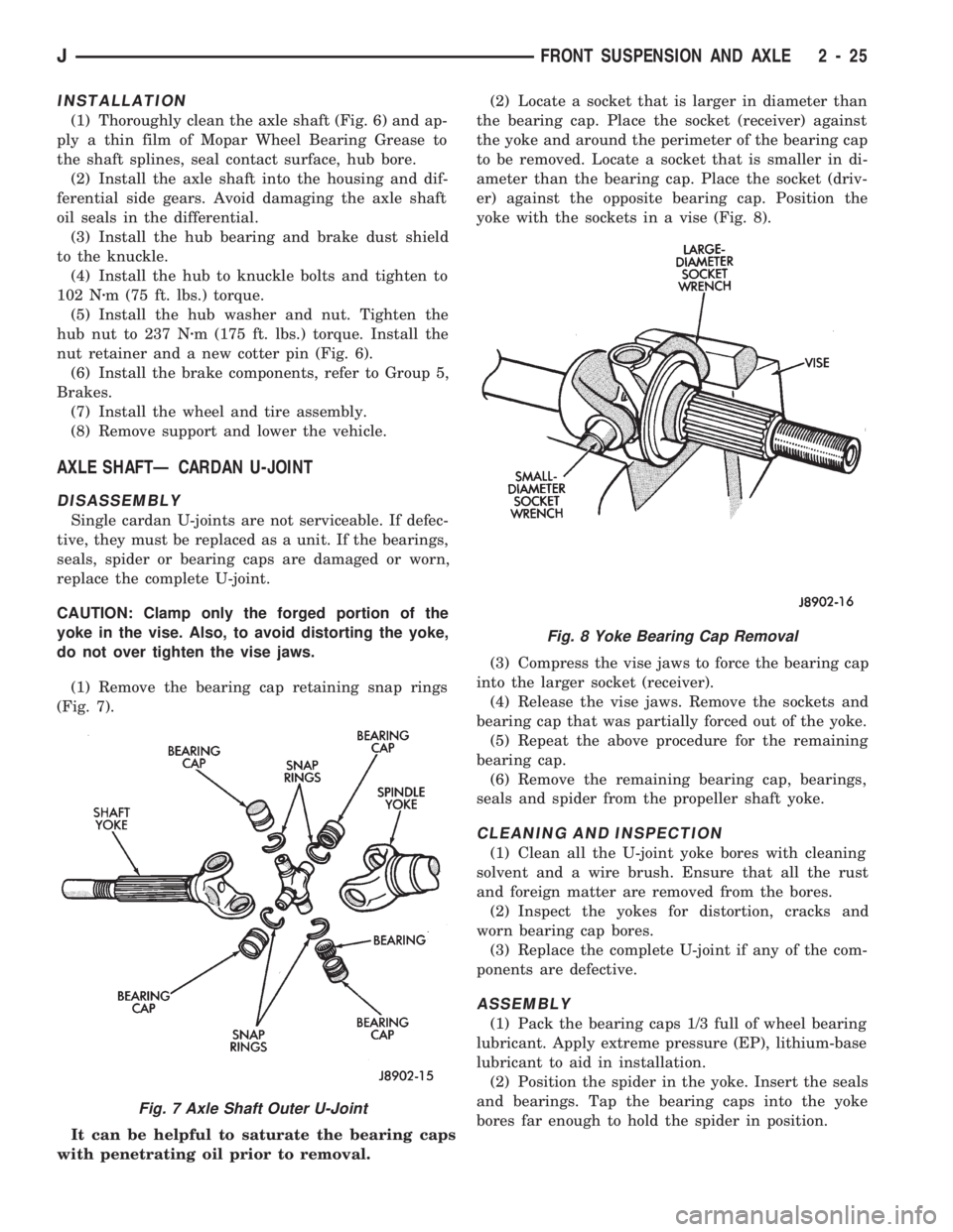
(1) Remove the bearing cap retaining snap rings
(Fig. 7).
It can be helpful to saturate the bearing caps
with penetrating oil prior to removal.(2) Locate a socket that is larger in diameter than
the bearing cap. Place the socket (receiver) against
the yoke and around the perimeter of the bearing cap
to be removed. Locate a socket that is smaller in di-
ameter than the bearing cap. Place the socket (driv-
er) against the opposite bearing cap. Position the
yoke with the sockets in a vise (Fig. 8).
(3) Compress the vise jaws to force the bearing cap
into the larger socket (receiver).
(4) Release the vise jaws. Remove the sockets and
bearing cap that was partially forced out of the yoke.
(5) Repeat the above procedure for the remaining
bearing cap.
(6) Remove the remaining bearing cap, bearings,
seals and spider from the propeller shaft yoke.
CLEANING AND INSPECTION
(1) Clean all the U-joint yoke bores with cleaning
solvent and a wire brush. Ensure that all the rust
and foreign matter are removed from the bores.
(2) Inspect the yokes for distortion, cracks and
worn bearing cap bores.
(3) Replace the complete U-joint if any of the com-
ponents are defective.
ASSEMBLY
(1) Pack the bearing caps 1/3 full of wheel bearing
lubricant. Apply extreme pressure (EP), lithium-base
lubricant to aid in installation.
(2) Position the spider in the yoke. Insert the seals
and bearings. Tap the bearing caps into the yoke
bores far enough to hold the spider in position.
Fig. 7 Axle Shaft Outer U-Joint
Fig. 8 Yoke Bearing Cap Removal
JFRONT SUSPENSION AND AXLE 2 - 25