1994 JEEP CHEROKEE radio
[x] Cancel search: radioPage 281 of 1784
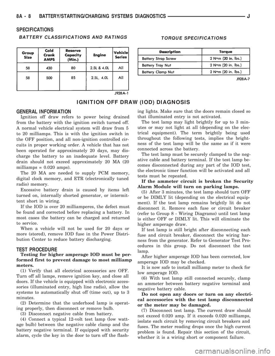
SPECIFICATIONS
IGNITION OFF DRAW (IOD) DIAGNOSIS
GENERAL INFORMATION
Ignition off draw refers to power being drained
from the battery with the ignition switch turned off.
A normal vehicle electrical system will draw from 5
to 20 milliamps. This is with the ignition switch in
the OFF position, and all non-ignition controlled cir-
cuits in proper working order. A vehicle that has not
been operated for approximately 20 days, may dis-
charge the battery to an inadequate level. Battery
drain should not exceed approximately 20 MA (20
milliamps = 0.020 amps).
The 20 MA are needed to supply PCM memory,
digital clock memory, and ETR (electronically tuned
radio) memory.
Excessive battery drain is caused by items left
turned on, internally shorted generator, or intermit-
tent short in wiring.
If the IOD is over 20 milliamperes, the defect must
be found and corrected before replacing a battery. In
most cases the battery can be charged and returned
to service.
When a vehicle will not be used for 20 days or
more (stored), remove IOD fuse in the Power Distri-
bution Center to reduce battery discharging.
TEST PROCEDURE
Testing for higher amperage IOD must be per-
formed first to prevent damage to most milliamp
meters.
(1) Verify that all electrical accessories are OFF.
Turn off all lamps, remove ignition key, and close all
doors. If the vehicle is equipped with electronic acces-
sories (illuminated entry, high line radio), allow the
systems to automatically shut off (time out), up to 3
minutes.
(2) Determine that the underhood lamp is operat-
ing properly, then disconnect or remove bulb.
(3) Disconnect negative cable from battery.
(4) Connect a typical 12-volt test lamp (low watt-
age bulb) between the negative cable clamp and the
battery negative terminal. If equipped with security
alarm, cycle the key in the door to turn off the flash-ing lights. Make sure that the doors remain closed so
that illuminated entry is not activated.
The test lamp may light brightly for up to 3 min-
utes or may not light at all (depending on the elec-
trical equipment). The term brightly being used
throughout the following tests, implies the bright-
ness of the test lamp will be the same as if it were
connected across the battery.
The test lamp must be securely clamped to the neg-
ative cable and battery terminal. If the test lamp be-
comes disconnected during any part of the IOD test,
the electronic timer function will be activated and all
tests must be repeated.
If the ammeter circuit is broken the Security
Alarm Module will turn on parking lamps.
(5) After 3 minutes, the test lamp should turn OFF
or be DIMLY lit (depending on the electrical equip-
ment). If the test lamp remains brightly lit do not
disconnect it. Remove each fuse or circuit breaker
(refer to Group 8 - Wiring Diagrams) until test lamp
is either OFF or DIMLY lit. This will eliminate the
higher amperage draw.
If test lamp is still bright after disconnecting each
fuse and circuit breaker, disconnect the wiring har-
ness from the generator. Refer to Generator Test Pro-
cedures in this group. Do not disconnect the test
lamp.
After higher amperage IOD has been corrected, low
amperage IOD may be checked.
It is now safe to install milliamp meter to check for
low amperage IOD.
(6) With test lamp still connected securely, clamp
an ammeter between battery negative terminal and
negative battery cable.
Do not open any doors or turn on any electri-
cal accessories with the test lamp disconnected
or the meter may be damaged.
(7) Disconnect test lamp. The current draw should
not exceed 0.020 amp. If it exceeds 0.020 milliamps,
isolate each circuit by removing circuit breakers and
fuses. The meter reading drops once the high current
problem is found. Repair this section of the circuit,
whether it is a wiring short or component failure.
BATTERY CLASSIFICATIONS AND RATINGSTORQUE SPECIFICATIONS
8A - 8 BATTERY/STARTING/CHARGING SYSTEMS DIAGNOSTICSJ
Page 295 of 1784
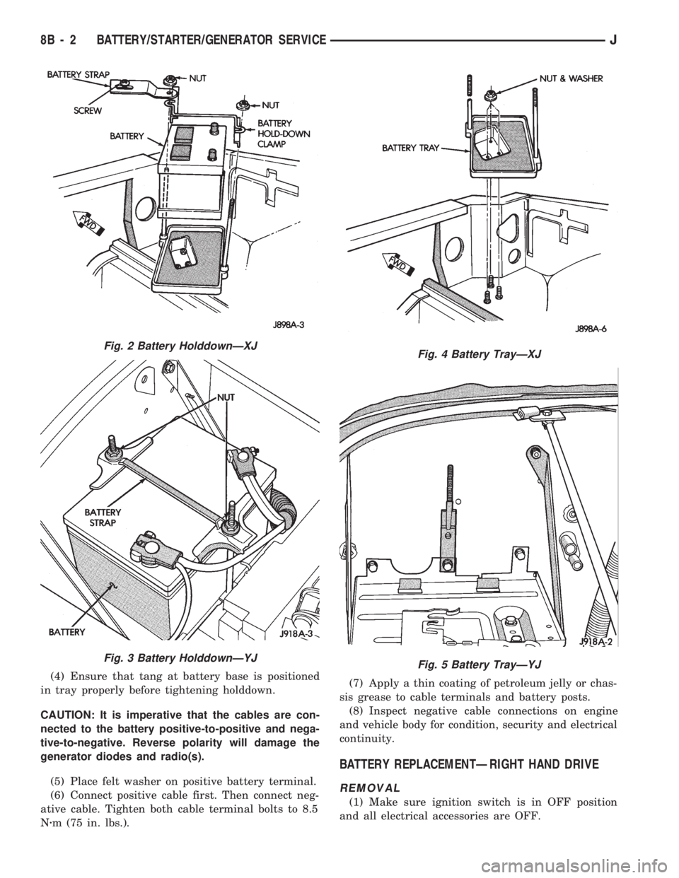
(4) Ensure that tang at battery base is positioned
in tray properly before tightening holddown.
CAUTION: It is imperative that the cables are con-
nected to the battery positive-to-positive and nega-
tive-to-negative. Reverse polarity will damage the
generator diodes and radio(s).
(5) Place felt washer on positive battery terminal.
(6) Connect positive cable first. Then connect neg-
ative cable. Tighten both cable terminal bolts to 8.5
Nzm (75 in. lbs.).(7) Apply a thin coating of petroleum jelly or chas-
sis grease to cable terminals and battery posts.
(8) Inspect negative cable connections on engine
and vehicle body for condition, security and electrical
continuity.
BATTERY REPLACEMENTÐRIGHT HAND DRIVE
REMOVAL
(1) Make sure ignition switch is in OFF position
and all electrical accessories are OFF.
Fig. 2 Battery HolddownÐXJ
Fig. 3 Battery HolddownÐYJ
Fig. 4 Battery TrayÐXJ
Fig. 5 Battery TrayÐYJ
8B - 2 BATTERY/STARTER/GENERATOR SERVICEJ
Page 296 of 1784
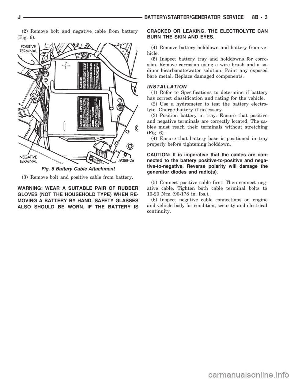
(2) Remove bolt and negative cable from battery
(Fig. 6).
(3) Remove bolt and positive cable from battery.
WARNING: WEAR A SUITABLE PAIR OF RUBBER
GLOVES (NOT THE HOUSEHOLD TYPE) WHEN RE-
MOVING A BATTERY BY HAND. SAFETY GLASSES
ALSO SHOULD BE WORN. IF THE BATTERY ISCRACKED OR LEAKING, THE ELECTROLYTE CAN
BURN THE SKIN AND EYES.
(4) Remove battery holddown and battery from ve-
hicle.
(5) Inspect battery tray and holddowns for corro-
sion. Remove corrosion using a wire brush and a so-
dium bicarbonate/water solution. Paint any exposed
bare metal. Replace damaged components.
INSTALLATION
(1) Refer to Specifications to determine if battery
has correct classification and rating for the vehicle.
(2) Use a hydrometer to test the battery electro-
lyte. Charge battery if necessary.
(3) Position battery in tray. Ensure that positive
and negative terminals are correctly located. The ca-
bles must reach their terminals without stretching
(Fig. 6).
(4) Ensure that battery base is positioned in tray
properly before tightening holddown.
CAUTION: It is imperative that the cables are con-
nected to the battery positive-to-positive and nega-
tive-to-negative. Reverse polarity will damage the
generator diodes and radio(s).
(5) Connect positive cable first. Then connect neg-
ative cable. Tighten both cable terminal bolts to
10-20 Nzm (90-178 in. lbs.).
(6) Inspect negative cable connections on engine
and vehicle body for condition, security and electrical
continuity.
Fig. 6 Battery Cable Attachment
JBATTERY/STARTER/GENERATOR SERVICE 8B - 3
Page 323 of 1784
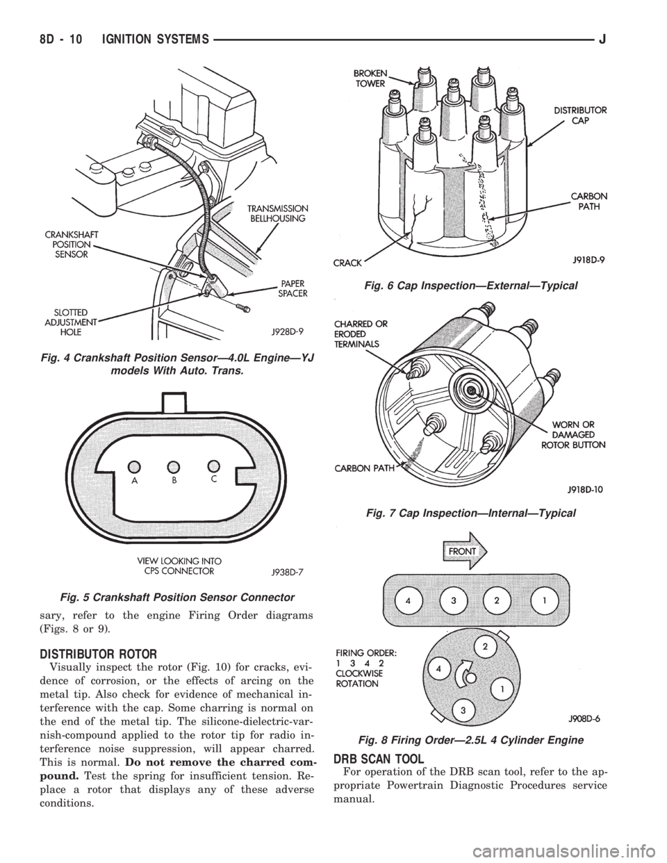
sary, refer to the engine Firing Order diagrams
(Figs. 8 or 9).
DISTRIBUTOR ROTOR
Visually inspect the rotor (Fig. 10) for cracks, evi-
dence of corrosion, or the effects of arcing on the
metal tip. Also check for evidence of mechanical in-
terference with the cap. Some charring is normal on
the end of the metal tip. The silicone-dielectric-var-
nish-compound applied to the rotor tip for radio in-
terference noise suppression, will appear charred.
This is normal.Do not remove the charred com-
pound.Test the spring for insufficient tension. Re-
place a rotor that displays any of these adverse
conditions.
DRB SCAN TOOL
For operation of the DRB scan tool, refer to the ap-
propriate Powertrain Diagnostic Procedures service
manual.
Fig. 4 Crankshaft Position SensorÐ4.0L EngineÐYJ
models With Auto. Trans.
Fig. 5 Crankshaft Position Sensor Connector
Fig. 6 Cap InspectionÐExternalÐTypical
Fig. 7 Cap InspectionÐInternalÐTypical
Fig. 8 Firing OrderÐ2.5L 4 Cylinder Engine
8D - 10 IGNITION SYSTEMSJ
Page 330 of 1784

plugs with scavenger deposits can be considered nor-
mal in condition and can be cleaned using standard
procedures.
CHIPPED ELECTRODE INSULATOR
A chipped electrode insulator usually results from
bending the center electrode while adjusting the
spark plug electrode gap. Under certain conditions,
severe detonation can also separate the insulator
from the center electrode (Fig. 27). Spark plugs with
this condition must be replaced.
PREIGNITION DAMAGE
Preignition damage is usually caused by excessive
combustion chamber temperature. The center elec-
trode dissolves first and the ground electrode dis-
solves somewhat latter (Fig. 28). Insulators appear
relatively deposit free. Determine if the spark plug
has the correct heat range rating for the engine. De-
termine if ignition timing is over advanced, or if
other operating conditions are causing engine over-
heating. (The heat range rating refers to the operat-
ing temperature of a particular type spark plug.
Spark plugs are designed to operate within specifictemperature ranges. This depends upon the thickness
and length of the center electrodes porcelain insula-
tor.)
SPARK PLUG OVERHEATING
Overheating is indicated by a white or gray center
electrode insulator that also appears blistered (Fig.
29). The increase in electrode gap will be consider-
ably in excess of 0.001 inch per 1000 miles of opera-
tion. This suggests that a plug with a cooler heat
range rating should be used. Over advanced ignition
timing, detonation and cooling system malfunctions
can also cause spark plug overheating.
SPARK PLUG SECONDARY CABLES
TESTING
Spark plug cables are sometimes referred to as sec-
ondary ignition cables or secondary wires. The cables
transfer electrical current from the distributor to in-
dividual spark plugs at each cylinder. The spark plug
cables are of nonmetallic construction and have a
built in resistance. The cables provide suppression of
radio frequency emissions from the ignition system.
Fig. 26 Scavenger Deposits
Fig. 27 Chipped Electrode Insulator
Fig. 28 Preignition Damage
Fig. 29 Spark Plug Overheating
JIGNITION SYSTEMS 8D - 17
Page 342 of 1784
cleaning, file the center electrode flat with a small
point file or jewelers file before adjusting gap.
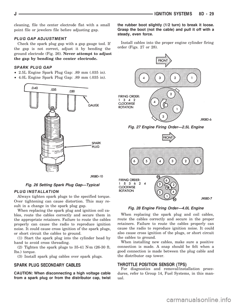
PLUG GAP ADJUSTMENT
Check the spark plug gap with a gap gauge tool. If
the gap is not correct, adjust it by bending the
ground electrode (Fig. 26).Never attempt to adjust
the gap by bending the center electrode.
SPARK PLUG GAP
²2.5L Engine Spark Plug Gap: .89 mm (.035 in).
²4.0L Engine Spark Plug Gap: .89 mm (.035 in).
PLUG INSTALLATION
Always tighten spark plugs to the specified torque.
Over tightening can cause distortion. This may re-
sult in a change in the spark plug gap.
When replacing the spark plug and ignition coil ca-
bles, route the cables correctly and secure them in
the appropriate retainers. Failure to route the cables
properly can cause the radio to reproduce ignition
noise. It could cause cross ignition of the spark plugs,
or short circuit the cables to ground.
(1) Start the spark plug into the cylinder head by
hand to avoid cross threading.
(2) Tighten the spark plugs to 35-41 Nzm (26-30 ft.
lbs.) torque.
(3) Install spark plug cables over spark plugs.
SPARK PLUG SECONDARY CABLES
CAUTION: When disconnecting a high voltage cable
from a spark plug or from the distributor cap, twistthe rubber boot slightly (1/2 turn) to break it loose.
Grasp the boot (not the cable) and pull it off with a
steady, even force.
Install cables into the proper engine cylinder firing
order (Figs. 27 or 28).
When replacing the spark plug and coil cables,
route the cables correctly and secure in the proper
retainers. Failure to route the cables properly can
cause the radio to reproduce ignition noise. It could
also cause cross ignition of the plugs, or short circuit
the cables to ground.
When installing new cables, make sure a positive
connection is made. A snap should be felt when a
good connection is made between the plug cable and
the distributor cap tower.
THROTTLE POSITION SENSOR (TPS)
For diagnostics and removal/installation proce-
dures, refer to Group 14, Fuel Systems, in this man-
ual.
Fig. 26 Setting Spark Plug GapÐTypical
Fig. 27 Engine Firing OrderÐ2.5L Engine
Fig. 28 Engine Firing OrderÐ4.0L Engine
JIGNITION SYSTEMS 8D - 29
Page 350 of 1784
INSTRUMENT CLUSTER DIAGNOSIS
INDEX
page page
4WD Indicator Inoperative................... 4
Anti-Lock Indicator......................... 4
Brake Indicator Inoperative.................. 4
Coolant Temperature Gauge Inoperative........ 3
Coolant Temperature Indicator Inoperative....... 3
Fuel Gauge Inoperative..................... 3
Gauges and Indicators Inoperative............ 3
Instrument Panel Lamps.................... 4
Low Fuel Warning Inoperative................ 4
Low Washer Indicator Inoperative............. 4Malfunction Indicator Lamp (Check Engine)...... 4
Oil Pressure Gauge Inoperative............... 3
Oil Pressure Indicator Inoperative............. 3
Radio/Clock Illumination.................... 4
Seat Belt Indicator........................ 4
Speedomete/Odometer Inoperative............. 3
Tachometer Inoperative..................... 3
Upshift Indicator Inoperative................. 4
Voltmeter Inoperative....................... 3
SPEEDOMETER/ODOMETER INOPERATIVE
(1) Check for continuity in the wire between the
vehicle speed sensor and cluster connector pin A5.
(2) With the ignition switch in the ON position,
check for battery voltage across pin A8 (B+) and pin
B2 (ground).
(3) Perform vehicle speed sensor test. Refer to the
appropriate vehicle Diagnostic Test Procedures man-
ual.
(4) If all the previous tests prove good, replace
speedometer/odometer.
GAUGES AND INDICATORS INOPERATIVE
(1) Remove and inspect fuse #17. Replace as re-
quired.
(2) Measure resistance at instrument cluster con-
nector terminal A3. Meter should read zero ohms. If
not, repair open to ground.
VOLTMETER INOPERATIVE
(1) Turn ignition switch to ON. Voltmeter should
read battery voltage. If not, go to step 2.
(2) Measure voltage at instrument cluster connec-
tor terminal A8. Meter should read battery voltage.
If OK, replace meter. If not, repair open to fuse #17.
OIL PRESSURE GAUGE INOPERATIVE
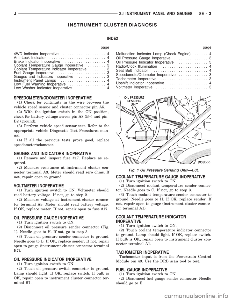
(1) Turn ignition switch to ON.
(2) Disconnect oil pressure sender connector (Fig.
1). Needle goes to H. If not, go to step 3.
(3) Touch oil pressure sender connector to ground.
Needle goes to L. If OK, replace sender. If not, repair
open to gauge (instrument cluster connector terminal
B7).
OIL PRESSURE INDICATOR INOPERATIVE
(1) Turn ignition switch to ON.
(2) Touch oil pressure switch connector to ground.
Lamp should light. If OK, replace switch. If bulb is
OK, repair open to instrument cluster connector ter-
minal B7.
COOLANT TEMPERATURE GAUGE INOPERATIVE
(1) Turn ignition switch to ON.
(2) Disconnect coolant temperature sender connec-
tor. Needle goes to C. If not, go to step 3.
(3) Touch coolant temperature sender connector to
ground. Needle goes to H. If OK, replace sender. If
not, repair open to gauge (instrument cluster connec-
tor terminal A1).
COOLANT TEMPERATURE INDICATOR
INOPERATIVE
(1) Turn ignition switch to ON.
(2) Touch coolant temperature indicator connector
to ground. Lamp should light. If OK, replace switch.
If bulb is OK, repair open to instrument cluster con-
nector terminal A1.
TACHOMETER INOPERATIVE
Tachometer input is from the Powertrain Control
Module pin 43. Use the DRB scan tool to test.
FUEL GAUGE INOPERATIVE
(1) Turn ignition switch to ON.
(2) Disconnect fuel gauge sender connector. Needle
should go to E.
Fig. 1 Oil Pressure Sending UnitÐ4.0L
JXJ INSTRUMENT PANEL AND GAUGES 8E - 3
Page 351 of 1784

(3) Connect a jumper between terminal A and B on
the body half of the fuel gauge sender connector. The
gauge should move to F. If gauge is OK, replace
sender. If not, go to step 4.
(4) Measure resistance of sender. Meter should
read 105 to 5 ohms. If OK, go to step 5. If not, re-
place sender.
(5) Check for an open between sender connector
and gauge. If OK, replace gauge. If not, repair open
to gauge.
LOW FUEL WARNING INOPERATIVE
(1) Turn ignition switch to ON.
(2) Disconnect terminal B1 of the instrument clus-
ter connector. Wait at least 10 seconds. Lamp (LED)
should light. If OK, replace sender. If not, replace
low fuel warning module.
UPSHIFT INDICATOR INOPERATIVE
(1) Turn ignition switch to ON.
(2) Ground pin 7 of connector B. Lamp should
light. If not, replace bulb. If OK, continue with
step 3.
(3) Turn ignition switch to OFF. Check for conti-
nuity between connector B pin 2 and pin 54 of the
Powertrain Control Module. If OK, replace PCM. If
not, repair open.
BRAKE INDICATOR INOPERATIVE
(1) Turn ignition switch to ON. Apply parking
brake, brake warning switch connector unplugged.
(2) Jumper brake warning switch connector termi-
nal B to ground. Lamp should light. If bulb is OK,
repair open to indicator.
(3) Turn ignition switch to OFF. Measure resis-
tance between brake warning switch connector ter-
minal A and ground. Meter should read zero ohms. If
OK, check switch and/or brake system. If not, repair
open to park brake switch ground.
4WD INDICATOR INOPERATIVE
(1) Apply parking brake, start engine, vehicle in
4WD Lock or 4WD.
(2) Unplug switch and touch harness side of wire
to ground. Lamp should light. If OK, check switch
operation, replace if bad. If bulb is OK, repair open
to indicator.
LOW WASHER INDICATOR INOPERATIVE
(1) Turn ignition switch to ON.
(2) Jumper 12 volts to fluid level switch connector
terminal B. Lamp should light. If not, go to step 3.
(3) Measure resistance between terminal B and
ground. Meter should read zero ohms. If not, repair
open to bulb. If OK, go to step 4.
(4) Measure voltage at fluid level switch connector
terminal A. Meter should read battery voltage. If
OK, replace switch. If not, repair open to fuse.
MALFUNCTION INDICATOR LAMP (CHECK ENGINE)
(1) Turn ignition switch to ON.
(2) Jumper Powertrain Control Module terminal 2
to ground. Lamp should light. If bulb is OK, check
for open to instrument cluster connector terminal 2.
ANTI-LOCK INDICATOR
(1) Turn ignition switch to ON.
(2) Jumper instrument cluster connector terminal
6 to ground. Lamp should light. If bulb is OK, check
wiring for an open to module. Refer to Group 5 -
Brakes.
SEAT BELT INDICATOR
Jumper instrument cluster connector terminal 15
to 12 volts. Lamp should light. If not, replace bulb. If
OK, check wiring for an open to buzzer module. Re-
fer to Group 8U - Chime/Buzzer Warning Systems.
RADIO/CLOCK ILLUMINATION
With the ignition switch in ACCESSORY or ON,
power comes from the radio fuse. It then goes
through the normally closed contacts of the radio il-
lumination relay to the radio at connector terminal
11.
Pulling the headlamp switch to ON energizes the
radio illumination relay. This closes the normally
open contacts of the relay, and the brightness for the
radio display is controlled by the headlamp switch
rheostat. The back-lighting for the radio is also con-
trolled by the headlamp rheostat through radio con-
nector terminal 10.
Refer to Group 8F - Audio Systems, for radio illu-
mination relay diagnosis.
INSTRUMENT PANEL LAMPS
Voltage is supplied at all times from the 40 amp
Maxi fuse (located in the Power Distribution Center)
through the park lamps fuse to the headlamp switch.
The circuit continues through the instrument lamps
fuse to the individual instrument panel lamps to
ground. Lamp brightness is controlled by turning the
headlamp switch knob.
DIAGNOSIS
(1) Turn parking lamps ON.
(2) Check park lamps fuse. Replace as required.
(3) Check instrument lamps fuse. Replace as re-
quired.
(4) Measure voltage at battery side of instrument
lamps fuse with rheostat turned counterclockwise to
clockwise (LO to HI). Meter should read zero volts to
battery voltage. If not, replace headlamp switch.
(5) Measure resistance at ground side of instru-
ment lamps fuse with parking lamps OFF. Meter
should read almost zero ohms (except bulb filament).
If not, repair open to ground. If zero ohms, 12 volt
supply wire from fuse is shorted to ground, repair short.
8E - 4 XJ INSTRUMENT PANEL AND GAUGESJ