1993 FORD MONDEO ECU
[x] Cancel search: ECUPage 72 of 279
inner wing panel, release the engine
wiring loom and refit the power steering
fluid reservoir.
(g) Secure the engine wiring loom neatly to
the engine/transmission so that it cannot
be damaged as the unit is removed from
the vehicle.
14Unbolt both parts of the exhaust manifold
heat shield; unclip the coolant hose to allow
the upper part to be withdrawn.
15Remove the auxiliary drivebelt (see
Chapter 1).
16Unbolt the power steering pump (see
Chapter 10); secure it as far as possible
(without disconnecting the system’s hoses)
clear of the engine/transmission.
17Raise the vehicle and support it securely
on axle stands, then remove the front
roadwheels. Drain the cooling system and (if
the engine is to be dismantled) drain the
engine oil and remove the oil filter (see
Chapter 1). Also drain the transmission as
described in the relevant Part of Chapter 7.
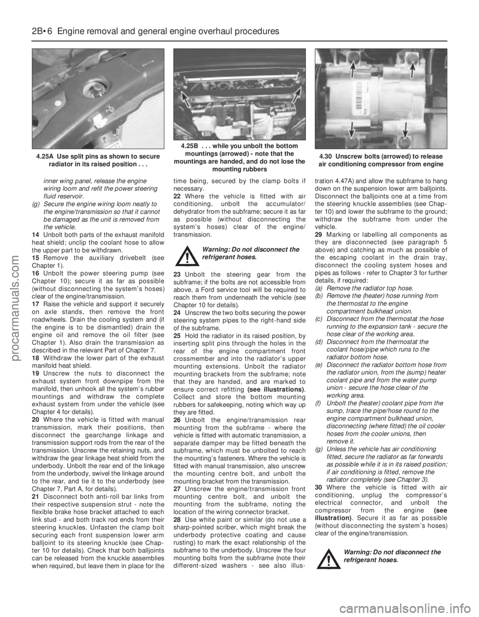
18Withdraw the lower part of the exhaust
manifold heat shield.
19Unscrew the nuts to disconnect the
exhaust system front downpipe from the
manifold, then unhook all the system’s rubber
mountings and withdraw the complete
exhaust system from under the vehicle (see
Chapter 4 for details).
20Where the vehicle is fitted with manual
transmission, mark their positions, then
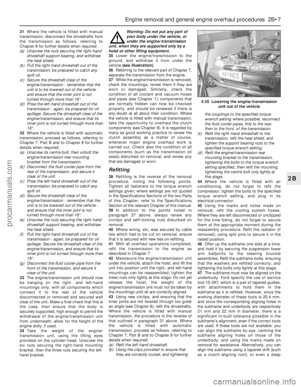
disconnect the gearchange linkage and
transmission support rods from the rear of the
transmission. Unscrew the retaining nuts, and
withdraw the gear linkage heat shield from the
underbody. Unbolt the rear end of the linkage
from the underbody, swivel the linkage around
to the rear, and tie it to the underbody (see
Chapter 7, Part A, for details).
21Disconnect both anti-roll bar links from
their respective suspension strut - note the
flexible brake hose bracket attached to each
link stud - and both track rod ends from their
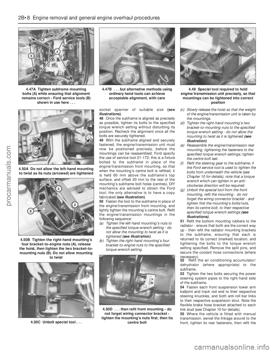
steering knuckles. Unfasten the clamp bolt
securing each front suspension lower arm
balljoint to its steering knuckle (see Chap-
ter 10 for details). Check that both balljoints
can be released from the knuckle assemblies
when required, but leave them in place for thetime being, secured by the clamp bolts if
necessary.
22Where the vehicle is fitted with air
conditioning, unbolt the accumulator/
dehydrator from the subframe; secure it as far
as possible (without disconnecting the
system’s hoses) clear of the engine/
transmission.
Warning: Do not disconnect the
refrigerant hoses.
23Unbolt the steering gear from the
subframe; if the bolts are not accessible from
above, a Ford service tool will be required to
reach them from underneath the vehicle (see
Chapter 10 for details).
24Unscrew the two bolts securing the power
steering system pipes to the right-hand side
of the subframe.
25Hold the radiator in its raised position, by
inserting split pins through the holes in the
rear of the engine compartment front
crossmember and into the radiator’s upper
mounting extensions. Unbolt the radiator
mounting brackets from the subframe; note
that they are handed, and are marked to
ensure correct refitting (see illustrations).
Collect and store the bottom mounting
rubbers for safekeeping, noting which way up
they are fitted.
26Unbolt the engine/transmission rear
mounting from the subframe - where the
vehicle is fitted with automatic transmission, a
separate damper may be fitted beneath the
subframe, which must be unbolted to reach
the mounting’s fasteners. Where the vehicle is
fitted with manual transmission, also unscrew
the mounting centre bolt, and unbolt the
mounting bracket from the transmission.
27Unscrew the engine/transmission front
mounting centre bolt, and unbolt the
mounting from the subframe, noting the
location of the wiring connector bracket.
28Use white paint or similar (do not use a
sharp-pointed scriber, which might break the
underbody protective coating and cause
rusting) to mark the exact relationship of the
subframe to the underbody. Unscrew the four
mounting bolts from the subframe (note their
different-sized washers - see also illus-tration 4.47A) and allow the subframe to hang
down on the suspension lower arm balljoints.
Disconnect the balljoints one at a time from
the steering knuckle assemblies (see Chap-
ter 10) and lower the subframe to the ground;
withdraw the subframe from under the
vehicle.
29Marking or labelling all components as
they are disconnected (see paragraph 5
above) and catching as much as possible of
the escaping coolant in the drain tray,
disconnect the cooling system hoses and
pipes as follows - refer to Chapter 3 for further
details, if required:
(a) Remove the radiator top hose.
(b) Remove the (heater) hose running from
the thermostat to the engine
compartment bulkhead union.
(c) Disconnect from the thermostat the hose
running to the expansion tank - secure the
hose clear of the working area.
(d) Disconnect from the thermostat the
coolant hose/pipe which runs to the
radiator bottom hose.
(e) Disconnect the radiator bottom hose from
the radiator union, from the (sump) heater
coolant pipe and from the water pump
union - secure the hose clear of the
working area.
(f) Unbolt the (heater) coolant pipe from the
sump, trace the pipe/hose round to the
engine compartment bulkhead union,
disconnecting (where fitted) the oil cooler
hoses from the cooler unions, then
remove it.
(g) Unless the vehicle has air conditioning
fitted, secure the radiator as far forwards
as possible while it is in its raised position;
if air conditioning is fitted, remove the
radiator completely (see Chapter 3).
30Where the vehicle is fitted with air
conditioning, unplug the compressor’s
electrical connector, and unbolt the
compressor from the engine (see
illustration). Secure it as far as possible
(without disconnecting the system’s hoses)
clear of the engine/transmission.
Warning: Do not disconnect the
refrigerant hoses.
2B•6 Engine removal and general engine overhaul procedures
4.25A Use split pins as shown to secure
radiator in its raised position . . .
4.25B . . . while you unbolt the bottom
mountings (arrowed) - note that the
mountings are handed, and do not lose the
mounting rubbers
4.30 Unscrew bolts (arrowed) to release
air conditioning compressor from engine
procarmanuals.com
Page 73 of 279
31Where the vehicle is fitted with manual
transmission, disconnect the driveshafts from
the transmission as follows, referring to
Chapter 8 for further details when required:
(a) Unscrew the nuts securing the right-hand
driveshaft support bearing, and withdraw
the heat shield.
(b) Pull the right-hand driveshaft out of the
transmission; be prepared to catch any
spilt oil.
(c) Secure the driveshaft clear of the
engine/transmission - remember that the
unit is to be lowered out of the vehicle -
and ensure that the inner joint is not
turned through more than 18°.
(d) Prise the left-hand driveshaft out of the
transmission - again, be prepared for oil
spillage. Secure the driveshaft clear of the
engine/transmission, and ensure that its
inner joint is not turned through more than
18°.
32Where the vehicle is fitted with automatic
transmission, proceed as follows, referring to
Chapter 7, Part B and to Chapter 8 for further
details when required:
(a) Unscrew its centre bolt, then unbolt the
engine/transmission rear mounting
bracket from the transmission.
(b) Disconnect the fluid cooler pipe from the
rear of the transmission, and secure it
clear of the unit.
(c) Prise the left-hand driveshaft out of the
transmission; be prepared to catch any
spilt oil.
(d) Secure the driveshaft clear of the
engine/transmission - remember that the
unit is to be lowered out of the vehicle -
and ensure that the inner joint is not
turned through more than 18°.
(e) Unscrew the nuts securing the right-hand
driveshaft support bearing, and withdraw
the heat shield.
(f) Pull the right-hand driveshaft out of the
transmission - again, be prepared for oil
spillage. Secure the driveshaft clear of the
engine/transmission, and ensure that its
inner joint is not turned through more than
18°.
(g) Disconnect the fluid cooler pipe from the
front of the transmission, and secure it
clear of the unit.
33The engine/transmission unit should now
be hanging on the right- and left-hand
mountings only, with all components which
connect it to the rest of the vehicle
disconnected or removed and secured well
clear of the unit. Make a final check that this is
the case, then ensure that the body is
securely supported, high enough to permit the
withdrawal of the engine/transmission unit
from underneath; allow for the height of the
engine dolly, if used.
34Take the weight of the engine/
transmission unit, using the lifting eyes
provided on the cylinder head. Unscrew the
six nuts securing the right-hand mounting
bracket, then the three nuts securing the left-
hand bracket. Warning: Do not put any part of
your body under the vehicle, or
under the engine/transmission
unit, when they are supported only by a
hoist or other lifting equipment.
35Lower the engine/transmission to the
ground, and withdraw it from under the
vehicle (see illustration).
36Referring to the relevant part of Chapter 7,
separate the transmission from the engine.
37While the engine/transmission is removed,
check the mountings; renew them if they are
worn or damaged. Similarly, check the
condition of all coolant and vacuum hoses
and pipes (see Chapter 1); components that
are normally hidden can now be checked
properly, and should be renewed if there is
any doubt at all about their condition. Where
the vehicle is fitted with manual transmission,
take the opportunity to overhaul the clutch
components (see Chapter 8). It is regarded by
many as good working practice to renew the
clutch assembly as a matter of course,
whenever major engine overhaul work is
carried out. Check also the condition of all
components (such as the transmission oil
seals) disturbed on removal, and renew any
that are damaged or worn.
Refitting
38Refitting is the reverse of the removal
procedure, noting the following points.
Tighten all fasteners to the torque wrench
settings given; where settings are not quoted
in the Specifications Sections of the two Parts
of this Chapter, refer to the Specifications
Section of the relevant Chapter of this manual.
39In addition to the points noted in
paragraph 37 above, always renew any
circlips and self-locking nuts disturbed on
removal.
40Where wiring, etc, was secured by cable
ties which had to be cut on removal, ensure
that it is secured with new ties on refitting.
41With all overhaul operations completed,
refit the transmission to the engine as
described in Chapter 7.
42Manoeuvre the engine/transmission unit
under the vehicle, attach the hoist, and lift the
unit into position until the right- and left-hand
mountings can be reassembled; tighten the
(new) nuts only lightly at this stage. Do not yet
release the hoist; the weight of the
engine/transmission unit must not be taken by
the mountings until all are correctly aligned.
43Using new circlips, and ensuring that the
inner joints are not twisted through too great
an angle (see Chapter 8), refit the driveshafts.
Where the vehicle is fitted with manual
transmission, the procedure is the reverse of
that outlined in paragraph 31 above. Where
the vehicle is fitted with automatic
transmission, proceed as follows, referring to
Chapter 7, Part B and to Chapter 8 for further
details when required:
(a) Refit the left-hand driveshaft.
(b) Using the clips provided to ensure that
they are correctly routed, and tighteningthe couplings to the specified torque
wrench setting where possible, reconnect
the fluid cooler pipes, first to the rear,
then to the front, of the transmission.
(c) Refit the right-hand driveshaft to the
transmission, refit the heat shield, and
tighten the support bearing nuts to the
specified torque wrench setting.
(d) Refit the engine/transmission rear
mounting bracket to the transmission,
tightening the bolts to the torque wrench
setting specified, then refit the mounting,
tightening the centre bolt only lightly at
this stage.
44Where the vehicle is fitted with air
conditioning, do not forget to refit the
compressor; tighten the bolts to the specified
torque wrench setting, and plug in its
electrical connector.
45Using the marks and notes made on
removal, refit the cooling system hoses.
Where they are left disconnected or unclipped
for the time being, do not forget to secure
them at the appropriate moment during the
reassembly procedure. Refit the radiator (if
removed), using split pins to secure it in the
raised position.
46Offer up the subframe one side at a time,
and hold it by securing the suspension lower
arm balljoints to the steering knuckle
assemblies. Refit the subframe bolts, ensuring
that the washers are refitted correctly, and
tightening the bolts only lightly at this stage.
47The subframe must now be aligned on the
underbody. Ford specify the use of service
tool 15-097, which is a pair of tapered guides,
with attachments to hold them in the
subframe as it is refitted. However, since the
working diameter of these tools is 20.4 mm,
and since the corresponding aligning holes in
the subframe and underbody are respectively
21 mm and 22 mm in diameter, there is a
significant in-built tolerance possible in the
subframe’s alignment, even if the correct tools
are used. If these tools are not available, you
can align the subframe by eye, centring the
subframe aligning holes on those of the
underbody, and using the marks made on
removal for assistance. Alternatively, you can
align the subframe using a tapered drift (such
as a clutch-aligning tool), or even a deep
Engine removal and general engine overhaul procedures 2B•7
2B
4.35 Lowering the engine/transmission
unit out of the vehicle
procarmanuals.com
Page 74 of 279
socket spanner of suitable size (see
illustrations).
48Once the subframe is aligned as precisely
as possible, tighten its bolts to the specified
torque wrench setting without disturbing its
position. Recheck the alignment once all the
bolts are securely tightened.
49With the subframe aligned and securely
fastened, the engine/transmission unit must
now be positioned precisely, before the
mountings can be reassembled. Ford specify
the use of service tool 21-172; this is a fixture
bolted to the subframe in place of the
engine/transmission front mounting, so that
when the mounting’s centre bolt is refitted, it
is held 60 mm above the subframe’s top
surface, and offset 20 mm to the rear of the
mounting’s subframe bolt holes (centres). DIY
mechanics are advised to obtain the Ford
tool; the only alternative is to have a copy
fabricated (see illustration).
50Fasten the tool to the subframe in place of
the engine/transmission front mounting, and
lightly tighten the mounting’s centre bolt. Refit
the engine/transmission mountings in the
following sequence:
(a) Tighten the left-hand mounting’s nuts to
the specified torque wrench setting - do
not allow the mounting to twist as it is
tightened (see illustration).
(b) Tighten the right-hand mounting’s four
bracket-to-engine nuts to the specified
torque wrench setting.(c) Slowly release the hoist so that the weight
of the engine/transmission unit is taken by
the mountings.
(d) Tighten the right-hand mounting’s two
bracket-to-mounting nuts to the specified
torque wrench setting - do not allow the
mounting to twist as it is tightened (see
illustration).
(e) Reassemble the engine/transmission rear
mounting, tightening the fasteners to the
specified torque wrench settings; tighten
the centre bolt last.
(f) Refit the steering gear to the subframe; if
the Ford service tool is used to tighten the
bolts from underneath the vehicle (see
Chapter 10 for details), note that a torque
wrench which can tighten in an anti-
clockwise direction will be required.
(g) Unbolt the special tool from the front
mounting, refit the mounting - do not
forget the wiring connector bracket - and
tighten first the mounting’s bolts/nuts,
then its centre bolt, to their respective
specified torque wrench settings (see
illustrations).
51Refit the bottom mounting rubbers to the
radiator - ensure that both are the correct way
up - then refit the radiator mounting brackets
to the subframe, ensuring that each is
returned to its correct (marked) location, and
tightening the bolts to the torque wrench
setting specified. Remove the split pins, and
secure the coolant hose connections (where
necessary).
52Refit the air conditioning accumulator/
dehydrator (where appropriate) to the
subframe.
53Tighten the two bolts securing the power
steering system pipes to the right-hand side
of the subframe.
54Fasten each front suspension lower arm
balljoint and track rod end to their respective
steering knuckles, and both anti-roll bar links
to their respective suspension strut. Note the
flexible brake hose bracket attached to each
link stud (see Chapter 10 for details).
55Where the vehicle is fitted with manual
transmission, swivel the linkage around to the
front, tighten its rear fasteners, then refit the
2B•8 Engine removal and general engine overhaul procedures
4.47A Tighten subframe mounting
bolts (A) while ensuring that alignment
remains correct - Ford service tools (B)
shown in use here . . .4.47B . . . but alternative methods using
ordinary hand tools can achieve
acceptable alignment, with care4.49 Special tool required to hold
engine/transmission unit precisely, so that
mountings can be tightened into correct
position
4.50B Tighten the right-hand mounting’s
four bracket-to-engine nuts (A), release
the hoist, then tighten the two bracket-to-
mounting nuts (B). Do not allow mounting
to twist
4.50A Do not allow the left-hand mounting
to twist as its nuts (arrowed) are tightened
4.50C Unbolt special tool . . .
4.50D . . . then refit front mounting - do
not forget wiring connector bracket -
tighten the mounting’s nuts first, then its
centre bolt
procarmanuals.com
Page 78 of 279
grinding or head resurfacing. Use
compressed air, if available, to blow out all the
oil holes and passages.
2Beginning at one end of the head, lubricate
and install the first valve. Apply molybdenum
disulphide-based grease or clean engine oil to
the valve stem, and refit the valve. Where the
original valves are being re-used, ensure that
each is refitted in its original guide. If new
valves are being fitted, insert them into the
locations to which they have been ground.
3Fit the plastic protector supplied with new
valve spring lower seat/stem oil seals to the
end of the valve stem, then put the new seal
squarely on top of the guide, and leave it
there; the action of refitting the valve spring
presses the lower seat/stem oil seal into place
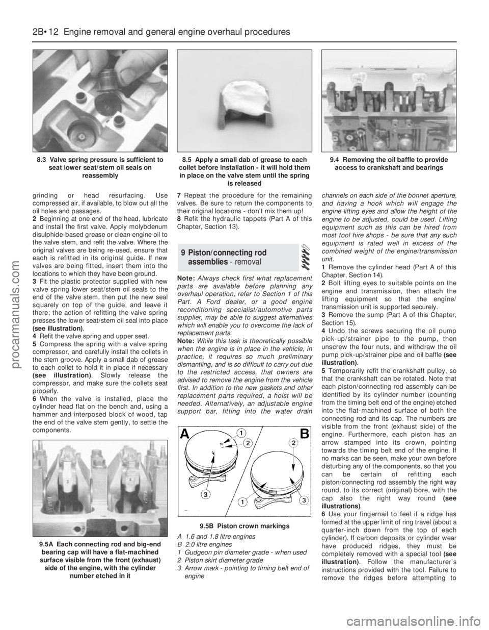
(see illustration).
4Refit the valve spring and upper seat.
5Compress the spring with a valve spring
compressor, and carefully install the collets in
the stem groove. Apply a small dab of grease
to each collet to hold it in place if necessary
(see illustration). Slowly release the
compressor, and make sure the collets seat
properly.
6When the valve is installed, place the
cylinder head flat on the bench and, using a
hammer and interposed block of wood, tap
the end of the valve stem gently, to settle the
components.7Repeat the procedure for the remaining
valves. Be sure to return the components to
their original locations - don’t mix them up!
8Refit the hydraulic tappets (Part A of this
Chapter, Section 13).
Note:Always check first what replacement
parts are available before planning any
overhaul operation; refer to Section 1 of this
Part. A Ford dealer, or a good engine
reconditioning specialist/automotive parts
supplier, may be able to suggest alternatives
which will enable you to overcome the lack of
replacement parts.
Note:While this task is theoretically possible
when the engine is in place in the vehicle, in
practice, it requires so much preliminary
dismantling, and is so difficult to carry out due
to the restricted access, that owners are
advised to remove the engine from the vehicle
first. In addition to the new gaskets and other
replacement parts required, a hoist will be
needed. Alternatively, an adjustable engine
support bar, fitting into the water drainchannels on each side of the bonnet aperture,
and having a hook which will engage the
engine lifting eyes and allow the height of the
engine to be adjusted, could be used. Lifting
equipment such as this can be hired from
most tool hire shops - be sure that any such
equipment is rated well in excess of the
combined weight of the engine/transmission
unit.
1Remove the cylinder head (Part A of this
Chapter, Section 14).
2Bolt lifting eyes to suitable points on the
engine and transmission, then attach the
lifting equipment so that the engine/
transmission unit is supported securely.
3Remove the sump (Part A of this Chapter,
Section 15).
4Undo the screws securing the oil pump
pick-up/strainer pipe to the pump, then
unscrew the four nuts, and withdraw the oil
pump pick-up/strainer pipe and oil baffle (see
illustration).
5Temporarily refit the crankshaft pulley, so
that the crankshaft can be rotated. Note that
each piston/connecting rod assembly can be
identified by its cylinder number (counting
from the timing belt end of the engine) etched
into the flat-machined surface of both the
connecting rod and its cap. The numbers are
visible from the front (exhaust side) of the
engine. Furthermore, each piston has an
arrow stamped into its crown, pointing
towards the timing belt end of the engine. If
no marks can be seen, make your own before
disturbing any of the components, so that you
can be certain of refitting each
piston/connecting rod assembly the right way
round, to its correct (original) bore, with the
cap also the right way round (see
illustrations).
6Use your fingernail to feel if a ridge has
formed at the upper limit of ring travel (about a
quarter-inch down from the top of each
cylinder). If carbon deposits or cylinder wear
have produced ridges, they must be
completely removed with a special tool (see
illustration). Follow the manufacturer’s
instructions provided with the tool. Failure to
remove the ridges before attempting to
9 Piston/connecting rod
assemblies- removal
2B•12 Engine removal and general engine overhaul procedures
8.3 Valve spring pressure is sufficient to
seat lower seat/stem oil seals on
reassembly8.5 Apply a small dab of grease to each
collet before installation - it will hold them
in place on the valve stem until the spring
is released9.4 Removing the oil baffle to provide
access to crankshaft and bearings
9.5A Each connecting rod and big-end
bearing cap will have a flat-machined
surface visible from the front (exhaust)
side of the engine, with the cylinder
number etched in it
9.5B Piston crown markings
A 1.6 and 1.8 litre engines
B 2.0 litre engines
1 Gudgeon pin diameter grade - when used
2 Piston skirt diameter grade
3 Arrow mark - pointing to timing belt end of
engine
procarmanuals.com
Page 79 of 279
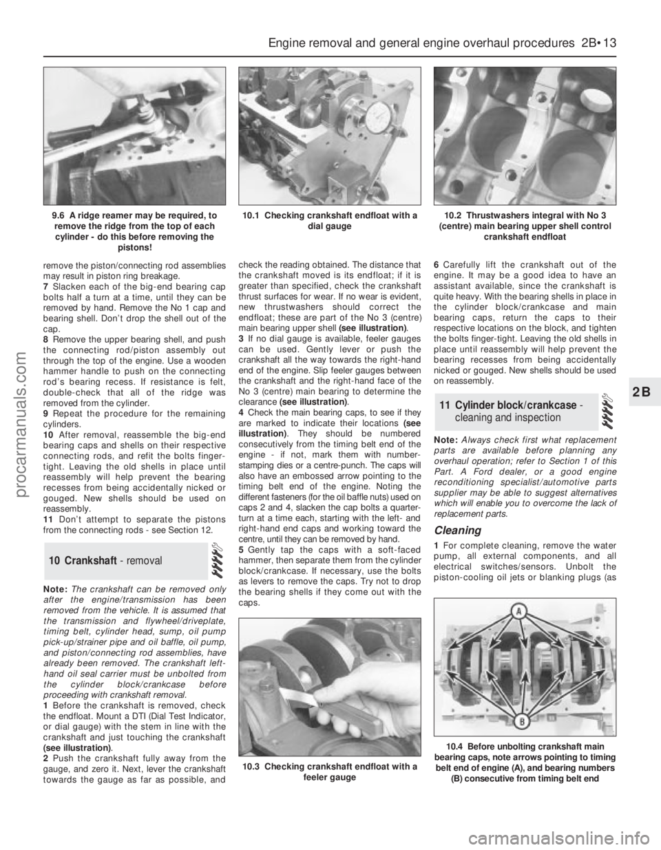
remove the piston/connecting rod assemblies
may result in piston ring breakage.
7Slacken each of the big-end bearing cap
bolts half a turn at a time, until they can be
removed by hand. Remove the No 1 cap and
bearing shell. Don’t drop the shell out of the
cap.
8Remove the upper bearing shell, and push
the connecting rod/piston assembly out
through the top of the engine. Use a wooden
hammer handle to push on the connecting
rod’s bearing recess. If resistance is felt,
double-check that all of the ridge was
removed from the cylinder.
9Repeat the procedure for the remaining
cylinders.
10After removal, reassemble the big-end
bearing caps and shells on their respective
connecting rods, and refit the bolts finger-
tight. Leaving the old shells in place until
reassembly will help prevent the bearing
recesses from being accidentally nicked or
gouged. New shells should be used on
reassembly.
11Don’t attempt to separate the pistons
from the connecting rods - see Section 12.
Note:The crankshaft can be removed only
after the engine/transmission has been
removed from the vehicle. It is assumed that
the transmission and flywheel/driveplate,
timing belt, cylinder head, sump, oil pump
pick-up/strainer pipe and oil baffle, oil pump,
and piston/connecting rod assemblies, have
already been removed. The crankshaft left-
hand oil seal carrier must be unbolted from
the cylinder block/crankcase before
proceeding with crankshaft removal.
1Before the crankshaft is removed, check
the endfloat. Mount a DTI (Dial Test Indicator,
or dial gauge) with the stem in line with the
crankshaft and just touching the crankshaft
(see illustration).
2Push the crankshaft fully away from the
gauge, and zero it. Next, lever the crankshaft
towards the gauge as far as possible, andcheck the reading obtained. The distance that
the crankshaft moved is its endfloat; if it is
greater than specified, check the crankshaft
thrust surfaces for wear. If no wear is evident,
new thrustwashers should correct the
endfloat; these are part of the No 3 (centre)
main bearing upper shell (see illustration).
3If no dial gauge is available, feeler gauges
can be used. Gently lever or push the
crankshaft all the way towards the right-hand
end of the engine. Slip feeler gauges between
the crankshaft and the right-hand face of the
No 3 (centre) main bearing to determine the
clearance (see illustration).
4Check the main bearing caps, to see if they
are marked to indicate their locations (see
illustration). They should be numbered
consecutively from the timing belt end of the
engine - if not, mark them with number-
stamping dies or a centre-punch. The caps will
also have an embossed arrow pointing to the
timing belt end of the engine. Noting the
different fasteners (for the oil baffle nuts) used on
caps 2 and 4, slacken the cap bolts a quarter-
turn at a time each, starting with the left- and
right-hand end caps and working toward the
centre, until they can be removed by hand.
5Gently tap the caps with a soft-faced
hammer, then separate them from the cylinder
block/crankcase. If necessary, use the bolts
as levers to remove the caps. Try not to drop
the bearing shells if they come out with the
caps.6Carefully lift the crankshaft out of the
engine. It may be a good idea to have an
assistant available, since the crankshaft is
quite heavy. With the bearing shells in place in
the cylinder block/crankcase and main
bearing caps, return the caps to their
respective locations on the block, and tighten
the bolts finger-tight. Leaving the old shells in
place until reassembly will help prevent the
bearing recesses from being accidentally
nicked or gouged. New shells should be used
on reassembly.
Note:Always check first what replacement
parts are available before planning any
overhaul operation; refer to Section 1 of this
Part. A Ford dealer, or a good engine
reconditioning specialist/automotive parts
supplier may be able to suggest alternatives
which will enable you to overcome the lack of
replacement parts.
Cleaning
1For complete cleaning, remove the water
pump, all external components, and all
electrical switches/sensors. Unbolt the
piston-cooling oil jets or blanking plugs (as
11 Cylinder block/crankcase -
cleaning and inspection
10 Crankshaft - removal
Engine removal and general engine overhaul procedures 2B•13
2B
10.3 Checking crankshaft endfloat with a
feeler gauge
10.4 Before unbolting crankshaft main
bearing caps, note arrows pointing to timing
belt end of engine (A), and bearing numbers
(B) consecutive from timing belt end
9.6 A ridge reamer may be required, to
remove the ridge from the top of each
cylinder - do this before removing the
pistons!10.1 Checking crankshaft endfloat with a
dial gauge10.2 Thrustwashers integral with No 3
(centre) main bearing upper shell control
crankshaft endfloat
procarmanuals.com
Page 81 of 279
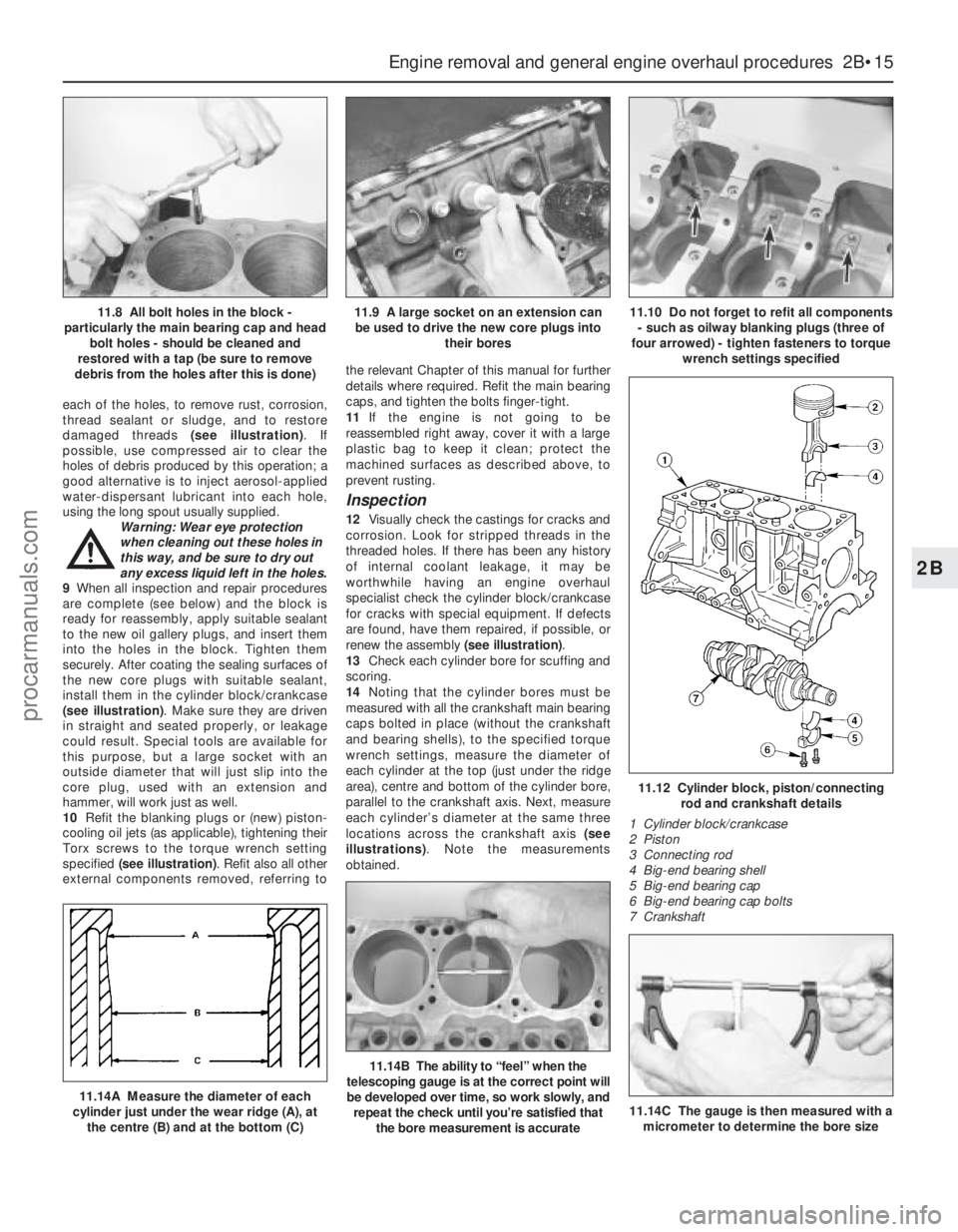
each of the holes, to remove rust, corrosion,
thread sealant or sludge, and to restore
damaged threads (see illustration). If
possible, use compressed air to clear the
holes of debris produced by this operation; a
good alternative is to inject aerosol-applied
water-dispersant lubricant into each hole,
using the long spout usually supplied.
Warning: Wear eye protection
when cleaning out these holes in
this way, and be sure to dry out
any excess liquid left in the holes.
9When all inspection and repair procedures
are complete (see below) and the block is
ready for reassembly, apply suitable sealant
to the new oil gallery plugs, and insert them
into the holes in the block. Tighten them
securely. After coating the sealing surfaces of
the new core plugs with suitable sealant,
install them in the cylinder block/crankcase
(see illustration). Make sure they are driven
in straight and seated properly, or leakage
could result. Special tools are available for
this purpose, but a large socket with an
outside diameter that will just slip into the
core plug, used with an extension and
hammer, will work just as well.
10Refit the blanking plugs or (new) piston-
cooling oil jets (as applicable), tightening their
Torx screws to the torque wrench setting
specified (see illustration). Refit also all other
external components removed, referring tothe relevant Chapter of this manual for further
details where required. Refit the main bearing
caps, and tighten the bolts finger-tight.
11If the engine is not going to be
reassembled right away, cover it with a large
plastic bag to keep it clean; protect the
machined surfaces as described above, to
prevent rusting.
Inspection
12Visually check the castings for cracks and
corrosion. Look for stripped threads in the
threaded holes. If there has been any history
of internal coolant leakage, it may be
worthwhile having an engine overhaul
specialist check the cylinder block/crankcase
for cracks with special equipment. If defects
are found, have them repaired, if possible, or
renew the assembly (see illustration).
13Check each cylinder bore for scuffing and
scoring.
14Noting that the cylinder bores must be
measured with all the crankshaft main bearing
caps bolted in place (without the crankshaft
and bearing shells), to the specified torque
wrench settings, measure the diameter of
each cylinder at the top (just under the ridge
area), centre and bottom of the cylinder bore,
parallel to the crankshaft axis. Next, measure
each cylinder’s diameter at the same three
locations across the crankshaft axis (see
illustrations). Note the measurements
obtained.
Engine removal and general engine overhaul procedures 2B•15
2B
11.12 Cylinder block, piston/connecting
rod and crankshaft details
1 Cylinder block/crankcase
2 Piston
3 Connecting rod
4 Big-end bearing shell
5 Big-end bearing cap
6 Big-end bearing cap bolts
7 Crankshaft
11.14A Measure the diameter of each
cylinder just under the wear ridge (A), at
the centre (B) and at the bottom (C)
11.14B The ability to “feel” when the
telescoping gauge is at the correct point will
be developed over time, so work slowly, and
repeat the check until you’re satisfied that
the bore measurement is accurate
11.8 All bolt holes in the block -
particularly the main bearing cap and head
bolt holes - should be cleaned and
restored with a tap (be sure to remove
debris from the holes after this is done)11.9 A large socket on an extension can
be used to drive the new core plugs into
their bores11.10 Do not forget to refit all components
- such as oilway blanking plugs (three of
four arrowed) - tighten fasteners to torque
wrench settings specified
11.14C The gauge is then measured with a
micrometer to determine the bore size
procarmanuals.com
Page 91 of 279
4If a hose proves stubborn, try to release it
by rotating it on its unions before attempting
to work it off. Gently prise the end of the hose
with a blunt instrument (such as a flat-bladed
screwdriver), but do not apply too much force,
and take care not to damage the pipe stubs or
hoses. Note in particular that the radiator hose
unions are fragile; do not use excessive force
when attempting to remove the hoses. If all
else fails, cut the hose with a sharp knife, then
slit it so that it can be peeled off in two pieces.
While expensive, this is preferable to buying a
new radiator. Check first, however, that a new
hose is readily available.
5When refitting a hose, first slide the clampsonto the hose, then work the hose onto its
unions. If the hose is stiff, use soap (or
washing-up liquid) as a lubricant, or soften it
by soaking it in boiling water, but take care to
prevent scalding.
6Work each hose end fully onto its union,
then check that the hose is settled correctly
and is properly routed. Slide each clip along
the hose until it is behind the union flared end,
before tightening it securely.
7Refill the system with coolant (see Chap-
ter 1).
8Check carefully for leaks as soon as
possible after disturbing any part of the
cooling system.Note:Refer to the warnings given in Section 1
of this Chapter before starting work.
Removal
1Disconnect the battery negative (earth) lead
(see Chapter 5, Section 1).
2Unbolt the resonator support bracket from
the engine compartment front crossmember.
Slacken the two clamp screws securing the
resonator to the air mass meter and plenum
chamber hoses, then swing the resonator up
clear of the thermostat housing (see Chap-
ter 4).
3Drain the cooling system (see Chapter 1). If
the coolant is relatively new or in good
condition, drain it into a clean container and
re-use it.
4Disconnect the expansion tank coolant
hose and the radiator top hose from the
thermostat housing’s water outlet.
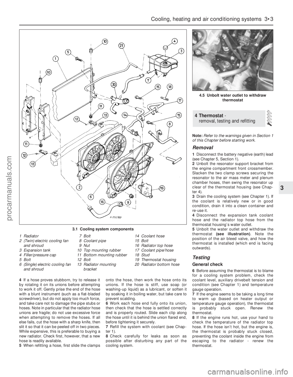
5Unbolt the water outlet and withdraw the
thermostat (see illustration). Note the
position of the air bleed valve, and how the
thermostat is installed (which end is facing
outwards).
Testing
General check
6Before assuming the thermostat is to blame
for a cooling system problem, check the
coolant level, auxiliary drivebelt tension and
condition (see Chapter 1) and temperature
gauge operation.
7If the engine seems to be taking a long time
to warm up (based on heater output or
temperature gauge operation), the thermostat
is probably stuck open. Renew the
thermostat.
8If the engine runs hot, use your hand to
check the temperature of the radiator top
hose. If the hose isn’t hot, but the engine is,
the thermostat is probably stuck closed,
preventing the coolant inside the engine from
escaping to the radiator - renew the
thermostat.
4 Thermostat -
removal, testing and refitting
Cooling, heating and air conditioning systems 3•3
3
4.5 Unbolt water outlet to withdraw
thermostat
3.1 Cooling system components
1 Radiator
2 (Twin) electric cooling fan
and shroud
3 Expansion tank
4 Filler/pressure cap
5 Bolt
6 (Single) electric cooling fan
and shroud7 Bolt
8 Coolant pipe
9 Nut
10 Top mounting rubber
11 Bottom mounting rubber
12 Bolt
13 Radiator mounting
bracket14 Coolant hose
15 Bolt
16 Radiator top hose
17 Coolant pipe/hose
18 Stud
19 Thermostat housing
20 Radiator bottom hose
procarmanuals.com
Page 92 of 279
Caution: Don’t drive the vehicle
without a thermostat. The lack of
a thermostat will slow warm-up
time. The engine management system’s
ECU will then stay in warm-up mode for
longer than necessary, causing emissions
and fuel economy to suffer.
9If the radiator top hose is hot, it means that
the coolant is flowing and the thermostat is
open. Consult the “Fault diagnosis”section at
the front of this manual to assist in tracing
possible cooling system faults.
Thermostat test
10If the thermostat remains in the open
position at room temperature, it is faulty, and
must be renewed as a matter of course.
11To test it fully, suspend the (closed)
thermostat on a length of string in a container
of cold water, with a thermometer beside it;
ensure that neither touches the side of the
container.
12Heat the water, and check the
temperature at which the thermostat begins to
open; compare this value with that specified.
Continue to heat the water until the
thermostat is fully open; the temperature at
which this should happen is stamped in the
unit’s end. Remove the thermostat and allow
it to cool down; check that it closes fully.
13If the thermostat does not open and close
as described, if it sticks in either position, or if
it does not open at the specified temperature,
it must be renewed.
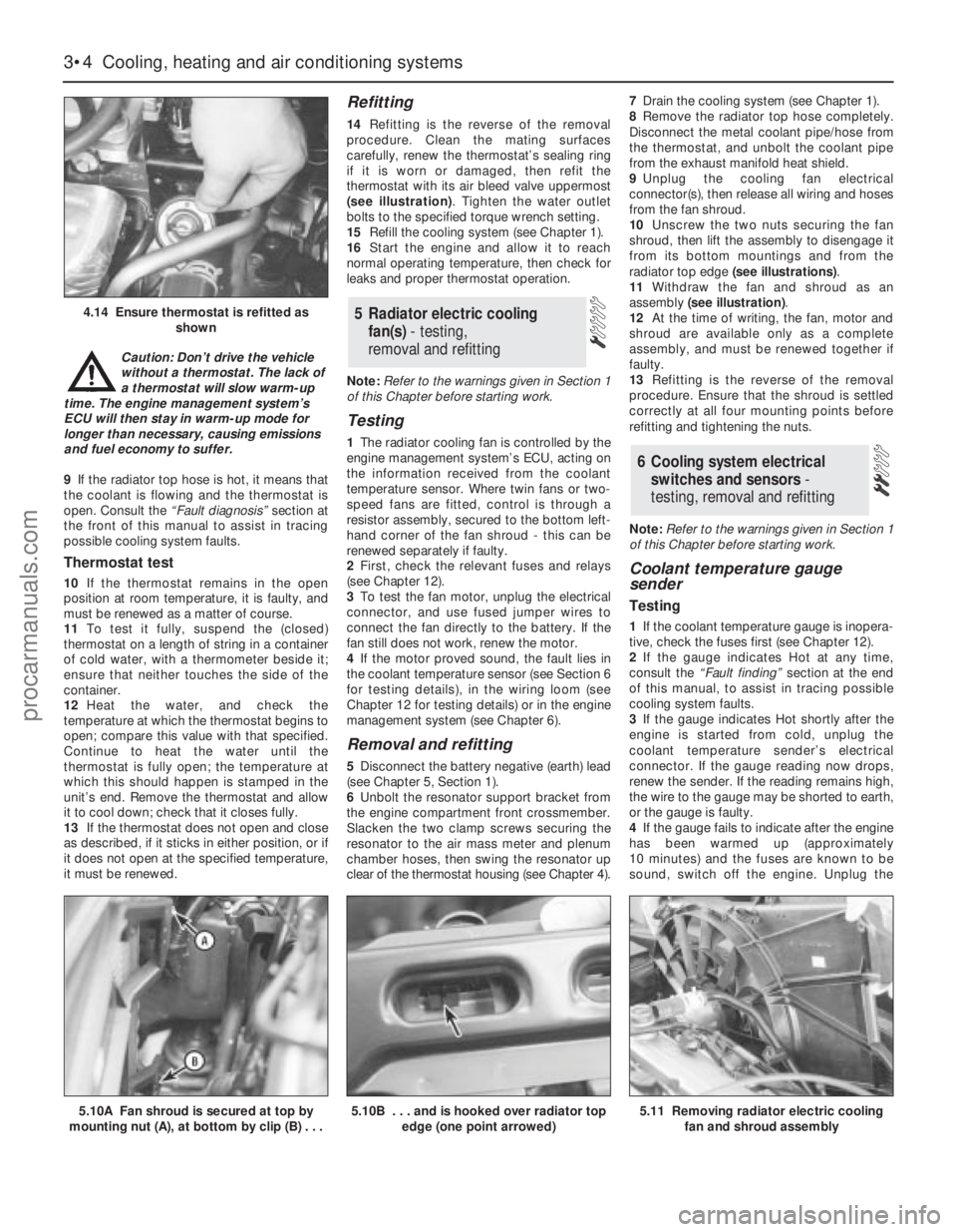
Refitting
14Refitting is the reverse of the removal
procedure. Clean the mating surfaces
carefully, renew the thermostat’s sealing ring
if it is worn or damaged, then refit the
thermostat with its air bleed valve uppermost
(see illustration). Tighten the water outlet
bolts to the specified torque wrench setting.
15Refill the cooling system (see Chapter 1).
16Start the engine and allow it to reach
normal operating temperature, then check for
leaks and proper thermostat operation.
Note:Refer to the warnings given in Section 1
of this Chapter before starting work.
Testing
1The radiator cooling fan is controlled by the
engine management system’s ECU, acting on
the information received from the coolant
temperature sensor. Where twin fans or two-
speed fans are fitted, control is through a
resistor assembly, secured to the bottom left-
hand corner of the fan shroud - this can be
renewed separately if faulty.
2First, check the relevant fuses and relays
(see Chapter 12).
3To test the fan motor, unplug the electrical
connector, and use fused jumper wires to
connect the fan directly to the battery. If the
fan still does not work, renew the motor.
4If the motor proved sound, the fault lies in
the coolant temperature sensor (see Section 6
for testing details), in the wiring loom (see
Chapter 12 for testing details) or in the engine
management system (see Chapter 6).
Removal and refitting
5Disconnect the battery negative (earth) lead
(see Chapter 5, Section 1).
6Unbolt the resonator support bracket from
the engine compartment front crossmember.
Slacken the two clamp screws securing the
resonator to the air mass meter and plenum
chamber hoses, then swing the resonator up
clear of the thermostat housing (see Chapter 4).7Drain the cooling system (see Chapter 1).
8Remove the radiator top hose completely.
Disconnect the metal coolant pipe/hose from
the thermostat, and unbolt the coolant pipe
from the exhaust manifold heat shield.
9Unplug the cooling fan electrical
connector(s), then release all wiring and hoses
from the fan shroud.
10Unscrew the two nuts securing the fan
shroud, then lift the assembly to disengage it
from its bottom mountings and from the
radiator top edge (see illustrations).
11Withdraw the fan and shroud as an
assembly (see illustration).
12At the time of writing, the fan, motor and
shroud are available only as a complete
assembly, and must be renewed together if
faulty.
13Refitting is the reverse of the removal
procedure. Ensure that the shroud is settled
correctly at all four mounting points before
refitting and tightening the nuts.
Note:Refer to the warnings given in Section 1
of this Chapter before starting work.
Coolant temperature gauge
sender
Testing
1If the coolant temperature gauge is inopera-
tive, check the fuses first (see Chapter 12).
2If the gauge indicates Hot at any time,
consult the “Fault finding”section at the end
of this manual, to assist in tracing possible
cooling system faults.
3If the gauge indicates Hot shortly after the
engine is started from cold, unplug the
coolant temperature sender’s electrical
connector. If the gauge reading now drops,
renew the sender. If the reading remains high,
the wire to the gauge may be shorted to earth,
or the gauge is faulty.
4If the gauge fails to indicate after the engine
has been warmed up (approximately
10 minutes) and the fuses are known to be
sound, switch off the engine. Unplug the
6 Cooling system electrical
switches and sensors-
testing, removal and refitting
5 Radiator electric cooling
fan(s)- testing,
removal and refitting
3•4 Cooling, heating and air conditioning systems
4.14 Ensure thermostat is refitted as
shown
5.10A Fan shroud is secured at top by
mounting nut (A), at bottom by clip (B) . . .5.10B . . . and is hooked over radiator top
edge (one point arrowed)5.11 Removing radiator electric cooling
fan and shroud assembly
procarmanuals.com