1993 FORD MONDEO engine oil
[x] Cancel search: engine oilPage 147 of 279
(a) Apply petroleum jelly or clean engine oil
to the sensor’s sealing O-ring.
(b) Locate the sensor fully in the cylinder
head, and wipe off any surplus lubricant
before securing it.
(c) Tighten the screw to the specified torque
wrench setting.
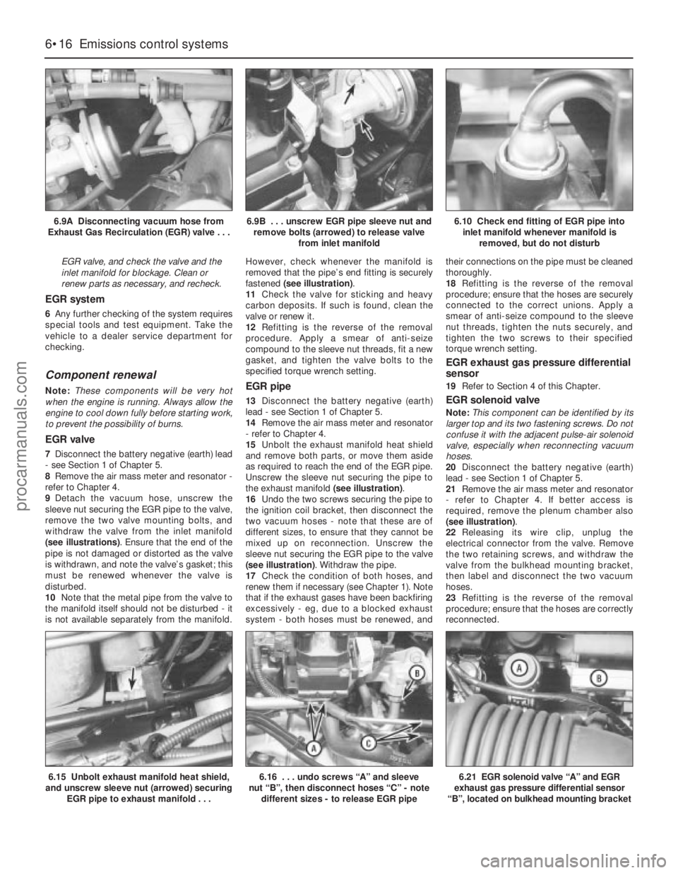
Coolant temperature sensor
48Refer to Chapter 3, Section 6.
Intake air temperature sensor
49Remove the air mass meter and resonator
(refer to Chapter 4) to gain access to the
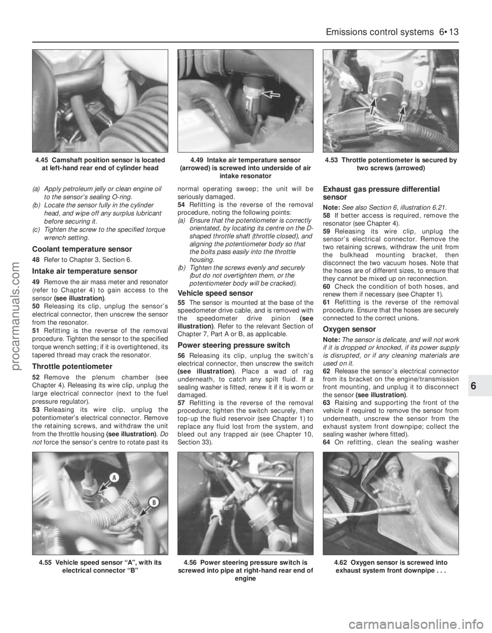
sensor (see illustration).
50Releasing its clip, unplug the sensor’s
electrical connector, then unscrew the sensor
from the resonator.
51Refitting is the reverse of the removal
procedure. Tighten the sensor to the specified
torque wrench setting; if it is overtightened, its
tapered thread may crack the resonator.
Throttle potentiometer
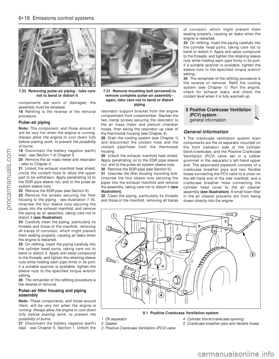
52Remove the plenum chamber (see
Chapter 4). Releasing its wire clip, unplug the
large electrical connector (next to the fuel
pressure regulator).
53Releasing its wire clip, unplug the
potentiometer’s electrical connector. Remove
the retaining screws, and withdraw the unit
from the throttle housing (see illustration). Do
notforce the sensor’s centre to rotate past itsnormal operating sweep; the unit will be
seriously damaged.
54Refitting is the reverse of the removal
procedure, noting the following points:
(a) Ensure that the potentiometer is correctly
orientated, by locating its centre on the D-
shaped throttle shaft (throttle closed), and
aligning the potentiometer body so that
the bolts pass easily into the throttle
housing.
(b) Tighten the screws evenly and securely
(but do not overtighten them, or the
potentiometer body will be cracked).
Vehicle speed sensor
55The sensor is mounted at the base of the
speedometer drive cable, and is removed with
the speedometer drive pinion (see
illustration). Refer to the relevant Section of
Chapter 7, Part A or B, as applicable.
Power steering pressure switch
56Releasing its clip, unplug the switch’s
electrical connector, then unscrew the switch
(see illustration). Place a wad of rag
underneath, to catch any spilt fluid. If a
sealing washer is fitted, renew it if it is worn or
damaged.
57Refitting is the reverse of the removal
procedure; tighten the switch securely, then
top-up the fluid reservoir (see Chapter 1) to
replace any fluid lost from the system, and
bleed out any trapped air (see Chapter 10,
Section 33).
Exhaust gas pressure differential
sensor
Note:See also Section 6, illustration 6.21.
58If better access is required, remove the
resonator (see Chapter 4).
59Releasing its wire clip, unplug the
sensor’s electrical connector. Remove the
two retaining screws, withdraw the unit from
the bulkhead mounting bracket, then
disconnect the two vacuum hoses. Note that
the hoses are of different sizes, to ensure that
they cannot be mixed up on reconnection.
60Check the condition of both hoses, and
renew them if necessary (see Chapter 1).
61Refitting is the reverse of the removal
procedure. Ensure that the hoses are securely
connected to the correct unions.
Oxygen sensor
Note:The sensor is delicate, and will not work
if it is dropped or knocked, if its power supply
is disrupted, or if any cleaning materials are
used on it.
62Release the sensor’s electrical connector
from its bracket on the engine/transmission
front mounting, and unplug it to disconnect
the sensor (see illustration).
63Raising and supporting the front of the
vehicle if required to remove the sensor from
underneath, unscrew the sensor from the
exhaust system front downpipe; collect the
sealing washer (where fitted).
64On refitting, clean the sealing washer
Emissions control systems 6•13
6
4.56 Power steering pressure switch is
screwed into pipe at right-hand rear end of
engine4.62 Oxygen sensor is screwed into
exhaust system front downpipe . . .
4.49 Intake air temperature sensor
(arrowed) is screwed into underside of air
intake resonator4.53 Throttle potentiometer is secured by
two screws (arrowed)
4.55 Vehicle speed sensor “A”, with its
electrical connector “B”
4.45 Camshaft position sensor is located
at left-hand rear end of cylinder head
procarmanuals.com
Page 150 of 279
EGR valve, and check the valve and the
inlet manifold for blockage. Clean or
renew parts as necessary, and recheck.
EGR system
6Any further checking of the system requires
special tools and test equipment. Take the
vehicle to a dealer service department for
checking.
Component renewal
Note:These components will be very hot
when the engine is running. Always allow the
engine to cool down fully before starting work,
to prevent the possibility of burns.
EGR valve
7Disconnect the battery negative (earth) lead
- see Section 1 of Chapter 5.
8Remove the air mass meter and resonator -
refer to Chapter 4.
9Detach the vacuum hose, unscrew the
sleeve nut securing the EGR pipe to the valve,
remove the two valve mounting bolts, and
withdraw the valve from the inlet manifold
(see illustrations). Ensure that the end of the
pipe is not damaged or distorted as the valve
is withdrawn, and note the valve’s gasket; this
must be renewed whenever the valve is
disturbed.
10Note that the metal pipe from the valve to
the manifold itself should not be disturbed - it
is not available separately from the manifold.However, check whenever the manifold is
removed that the pipe’s end fitting is securely
fastened (see illustration).
11Check the valve for sticking and heavy
carbon deposits. If such is found, clean the
valve or renew it.
12Refitting is the reverse of the removal
procedure. Apply a smear of anti-seize
compound to the sleeve nut threads, fit a new
gasket, and tighten the valve bolts to the
specified torque wrench setting.
EGR pipe
13Disconnect the battery negative (earth)
lead - see Section 1 of Chapter 5.
14Remove the air mass meter and resonator
- refer to Chapter 4.
15Unbolt the exhaust manifold heat shield
and remove both parts, or move them aside
as required to reach the end of the EGR pipe.
Unscrew the sleeve nut securing the pipe to
the exhaust manifold (see illustration).
16Undo the two screws securing the pipe to
the ignition coil bracket, then disconnect the
two vacuum hoses - note that these are of
different sizes, to ensure that they cannot be
mixed up on reconnection. Unscrew the
sleeve nut securing the EGR pipe to the valve
(see illustration). Withdraw the pipe.
17Check the condition of both hoses, and
renew them if necessary (see Chapter 1). Note
that if the exhaust gases have been backfiring
excessively - eg, due to a blocked exhaust
system - both hoses must be renewed, andtheir connections on the pipe must be cleaned
thoroughly.
18Refitting is the reverse of the removal
procedure; ensure that the hoses are securely
connected to the correct unions. Apply a
smear of anti-seize compound to the sleeve
nut threads, tighten the nuts securely, and
tighten the two screws to their specified
torque wrench setting.
EGR exhaust gas pressure differential
sensor
19Refer to Section 4 of this Chapter.
EGR solenoid valve
Note:This component can be identified by its
larger top and its two fastening screws. Do not
confuse it with the adjacent pulse-air solenoid
valve, especially when reconnecting vacuum
hoses.
20Disconnect the battery negative (earth)
lead - see Section 1 of Chapter 5.
21Remove the air mass meter and resonator
- refer to Chapter 4. If better access is
required, remove the plenum chamber also
(see illustration).
22Releasing its wire clip, unplug the
electrical connector from the valve. Remove
the two retaining screws, and withdraw the
valve from the bulkhead mounting bracket,
then label and disconnect the two vacuum
hoses.
23Refitting is the reverse of the removal
procedure; ensure that the hoses are correctly
reconnected.
6•16 Emissions control systems
6.9A Disconnecting vacuum hose from
Exhaust Gas Recirculation (EGR) valve . . .6.9B . . . unscrew EGR pipe sleeve nut and
remove bolts (arrowed) to release valve
from inlet manifold6.10 Check end fitting of EGR pipe into
inlet manifold whenever manifold is
removed, but do not disturb
6.15 Unbolt exhaust manifold heat shield,
and unscrew sleeve nut (arrowed) securing
EGR pipe to exhaust manifold . . .6.16 . . . undo screws “A” and sleeve
nut “B”, then disconnect hoses “C” - note
different sizes - to release EGR pipe6.21 EGR solenoid valve “A” and EGR
exhaust gas pressure differential sensor
“B”, located on bulkhead mounting bracket
procarmanuals.com
Page 152 of 279
components are worn or damaged, the
assembly must be renewed.
18Refitting is the reverse of the removal
procedure.
Pulse-air piping
Note:This component, and those around it,
will be very hot when the engine is running.
Always allow the engine to cool down fully
before starting work, to prevent the possibility
of burns.
19Disconnect the battery negative (earth)
lead - see Section 1 of Chapter 5.
20Remove the air mass meter and resonator
- refer to Chapter 4.
21Unbolt the exhaust manifold heat shield;
unclip the coolant hose to allow the upper
part to be withdrawn. Apply penetrating oil to
the EGR pipe sleeve nut, and to the pulse-air
system sleeve nuts.
22Remove the EGR pipe (see Section 6).
23Remove the screws securing the filter
housing to the piping - see illustration 7.16.
Unscrew the four sleeve nuts securing the
pipes into the exhaust manifold, and remove
the piping as an assembly, taking care not to
distort it (see illustration).
24Carefully clean the piping, particularly its
threads and those of the manifold, removing
all traces of corrosion, which might prevent
them seating properly, causing air leaks when
the engine is restarted.
25On refitting, insert the piping carefully into
the cylinder head ports, taking care not to
bend or distort it. Apply anti-seize compound
to the threads, and tighten the retaining sleeve
nuts while holding each pipe firmly in its port;
if a suitable spanner is available, tighten the
sleeve nuts to the specified torque wrench
setting.
26The remainder of the refitting procedure is
the reverse of removal.
Pulse-air filter housing and piping
assembly
Note:These components, and those around
them, will be very hot when the engine is
running. Always allow the engine to cool down
fully before starting work, to prevent the
possibility of burns.
27Disconnect the battery negative (earth)
lead - see Chapter 5, Section 1. Unbolt theresonator support bracket from the engine
compartment front crossmember. Slacken the
two clamp screws securing the resonator to
the air mass meter and plenum chamber
hoses, then swing the resonator up clear of
the thermostat housing (see Chapter 4).
28Drain the cooling system (see Chapter 1)
and disconnect the coolant hose and the
coolant pipe/hose from the thermostat
housing.
29Unbolt the exhaust manifold heat shield.
Apply penetrating oil to the EGR pipe sleeve
nut, and to the pulse-air system sleeve nuts.
30Remove the EGR pipe (see Section 6).
31Unscrew the filter housing mounting bolt.
Unscrew the four sleeve nuts securing the
pipes into the exhaust manifold and remove
the assembly, taking care not to distort it (see
illustration).
32Clean the piping, particularly its threads
and those of the manifold, removing all tracesof corrosion, which might prevent them
seating properly, causing air leaks when the
engine is restarted.
33On refitting, insert the piping carefully into
the cylinder head ports, taking care not to
bend or distort it. Apply anti-seize compound
to the threads, and tighten the retaining sleeve
nuts while holding each pipe firmly in its port;
if a suitable spanner is available, tighten the
sleeve nuts to the specified torque wrench
setting.
34The remainder of the refitting procedure is
the reverse of removal. Refill the cooling
system (see Chapter 1). Run the engine,
check for exhaust leaks, and check the
coolant level when it is fully warmed-up.
General information
1The crankcase ventilation system main
components are the oil separator mounted on
the front (radiator) side of the cylinder
block/crankcase, and the Positive Crankcase
Ventilation (PCV) valve set in a rubber
grommet in the separator’s left-hand upper
end. The associated pipework consists of a
crankcase breather pipe and two flexible
hoses connecting the PCV valve to a union on
the left-hand end of the inlet manifold, and a
crankcase breather hose connecting the
cylinder head cover to the air cleaner
assembly (see illustration). A small foam filter
in the air cleaner prevents dirt from being
drawn directly into the engine.
8 Positive Crankcase Ventilation
(PCV) system -
general information
6•18 Emissions control systems
7.23 Removing pulse-air piping - take care
not to bend or distort it7.31 Remove mounting bolt (arrowed) to
remove complete pulse-air assembly -
again, take care not to bend or distort
piping
8.1 Positive Crankcase Ventilation system
1 Oil separator
2 Gasket
3 Positive Crankcase Ventilation (PCV) valve4 Cylinder block/crankcase opening
5 Crankcase breather pipe and flexible hoses
procarmanuals.com
Page 153 of 279
2The function of these components is to
reduce the emission of unburned
hydrocarbons from the crankcase, and to
minimise the formation of oil sludge. By
ensuring that a depression is created in the
crankcase under most operating conditions,
particularly at idle, and by positively inducing
fresh air into the system, the oil vapours and
“blow-by” gases collected in the crankcase
are drawn from the crankcase, through the oil
separator, into the inlet tract, to be burned by
the engine during normal combustion.
Checking
3Checking procedures for the system
components are included in Chapter 1.
Component renewal
Cylinder head-to-air cleaner hose
4See Chapter 1.
Positive Crankcase Ventilation (PCV)
valve
5The valve is plugged into the oil separator.
Depending on the tools available, access to
the valve may be possible once the pulse-air
assembly has been removed (see Section 7).
If this is not feasible, proceed as outlined in
paragraph 6 below.
Oil separator
6Remove the exhaust manifold (see Chap-
ter 2, Part A). The Positive Crankcase
Ventilation (PCV) valve can now be unplugged
and flushed, or renewed, as required, as
described in Chapter 1.
7Unbolt the oil separator from the cylinder
block/crankcase, and withdraw it; remove and
discard the gasket.
8Flush out or renew the oil separator, as
required (see Chapter 1).
9On reassembly, fit a new gasket, and
tighten the fasteners to the torque wrench
settings given in the Specifications Section of
Chapter 2, Part B.
10The remainder of the refitting procedure is
the reverse of removal. Refill the cooling
system (see Chapter 1). Run the engine,
check for exhaust leaks, and check the
coolant level when it is fully warmed-up.
General information
1The exhaust gases of any petrol engine
(however efficient or well-tuned) consist
largely (approximately 99 %) of nitrogen (N
2),
carbon dioxide (CO
2), oxygen (O2), other inert
gases and water vapour (H
2O). The remaining
1 % is made up of the noxious materials
which are currently seen (CO
2apart) as the
major polluters of the environment: carbon
monoxide (CO), unburned hydrocarbons (HC),oxides of nitrogen (NO
x) and some solid
matter, including a small lead content.
2Left to themselves, most of these pollutants
are thought eventually to break down naturally
(CO and NO
x, for example, break down in the
upper atmosphere to release CO
2) having first
caused ground-level environmental problems.
The massive increase world-wide in the use of
motor vehicles, and the current popular
concern for the environment has caused the
introduction in most countries of legislation, in
varying degrees of severity, to combat the
problem.
3The device most commonly used to clean
up vehicle exhausts is the catalytic converter.
It is fitted into the vehicle’s exhaust system,
and uses precious metals (platinum and
palladium or rhodium) as catalysts to speed
up the reaction between the pollutants and
the oxygen in the vehicle’s exhaust gases, CO
and HC being oxidised to form H
2O and CO2and (in the three-way type of catalytic
converter) NO
xbeing reduced to N2. Note:
The catalytic converter is not a filter in the
physical sense; its function is to promote a
chemical reaction, but it is not itself affected
by that reaction.
4The converter consists of an element (or
“substrate”) of ceramic honeycomb, coated
with a combination of precious metals in such
a way as to produce a vast surface area over
which the exhaust gases must flow; the whole
being mounted in a stainless-steel box. A
simple “oxidation” (or “two-way”) catalytic
converter can deal with CO and HC only,
while a “reduction” (or “three-way”) catalytic
converter can deal with CO, HC and NO
x.
Three-way catalytic converters are further
sub-divided into “open-loop” (or
“uncontrolled”) converters which can remove
50 to 70 % of pollutants and “closed-loop”
(also known as “controlled” or “regulated”)
converters which can remove over 90 % of
pollutants.
5The catalytic converter fitted to the Mondeo
models covered in this manual is of the three-
way closed-loop type.
6The catalytic converter is a reliable and
simple device, which needs no maintenance
in itself, but there are some facts of which an
owner should be aware if the converter is to
function properly for its full service life.
(a) DO NOT use leaded petrol in a vehicle
equipped with a catalytic converter - the
lead will coat the precious metals,
reducing their converting efficiency, and
will eventually destroy the converter; it will
also affect the operation of the oxygen
sensor, requiring its renewal if lead-
fouled. Opinions vary as to how much
leaded fuel is necessary to affect the
converter’s performance, and whether it
can recover even if only unleaded petrol is
used afterwards; the best course of action
is, therefore, to assume the worst, and to
ensure that NO leaded petrol is used at
any time.
(b) Always keep the ignition and fuel systemswell-maintained in accordance with the
manufacturer’s schedule (Chapter 1) -
particularly, ensure that the air filter
element, the fuel filter and the spark plugs
are renewed at the correct intervals. If the
intake air/fuel mixture is allowed to
become too rich due to neglect, the
unburned surplus will enter and burn in
the catalytic converter, overheating the
element and eventually destroying the
converter.
(c) If the engine develops a misfire, do not
drive the vehicle at all (or at least as little
as possible) until the fault is cured - the
misfire will allow unburned fuel to enter
the converter, which will result in its
overheating, as noted above. For the
same reason, do not persist if the engine
refuses to start - either trace the problem
and cure it yourself, or have the vehicle
checked immediately by a qualified
mechanic.
(d) Avoid allowing the vehicle to run out of
petrol.
(e) DO NOT push- or tow-start the vehicle
unless no other alternative exists,
especially if the engine and exhaust are at
normal operating temperature. Starting
the engine in this way may soak the
catalytic converter in unburned fuel,
causing it to overheat when the engine
does start - see (b) above.
(f) DO NOT switch off the ignition at high
engine speeds, in particular, do not “blip”
the throttle immediately before switching
off. If the ignition is switched off at
anything above idle speed, unburned fuel
will enter the (very hot) catalytic converter,
with the possible risk of its igniting on the
element and damaging the converter.
(g) Avoid repeated successive cold starts
followed by short journeys. If the
converter is never allowed to reach its
proper working temperature, it will gather
unburned fuel, allowing some to pass into
the atmosphere and the rest to soak in
the element, causing it to overheat when
a long journey is made - see (b) above.
(h) DO NOT use fuel or engine oil additives -
these may contain substances harmful to
the catalytic converter. Similarly, DO NOT
use silicone-based sealants on any part of
the engine or fuel system, and do not use
exhaust sealants on any part of the
exhaust system upstream of the catalytic
converter. Even if the sealant itself does
not contain additives harmful to the
converter, pieces of it may break off and
foul the element, causing local
overheating.
(i) DO NOT continue to use the vehicle if the
engine burns oil to the extent of leaving a
visible trail of blue smoke. Unburned
carbon deposits will clog the converter
passages and reduce its efficiency; in
severe cases, the element will overheat.
(j) Remember that the catalytic converter
operates at very high temperatures -
9 Catalytic converter -
general information, checking
and component renewal
Emissions control systems 6•19
6
procarmanuals.com
Page 162 of 279
spring must now be carefully released from
the compressor. If it is to be re-used, the
spring can be left in compression.
7With the strut assembly now completely
dismantled, examine all the components for
wear and damage, and check the bearing for
smoothness of operation. Renew components
as necessary.
8Examine the strut for signs of fluid leakage.
Check the strut piston for signs of pitting
along its entire length, and check the strut
body for signs of damage. Test the operation
of the strut, while holding it in an upright
position, by moving the piston through a full
stroke, and then through short strokes of 50
to 100 mm. In both cases, the resistance felt
should be smooth and continuous. If the
resistance is jerky, uneven, or if there is any
visible sign of wear or damage to the strut,
renewal is necessary.
9Reassembly is a reversal of dismantling,
noting the following points:
(a) Make sure that the coil spring ends are
correctly located in the upper and lower
seats before releasing the compressor.
(b) Check that the bearing is correctly fitted
to the piston rod seat.
(c) Tighten the thrust bearing retaining nut to
the specified torque.
Removal
1Apply the handbrake, jack up the front of
the vehicle and support it on axle stands.
Remove both front wheels.
2Unscrew the nuts, and disconnect the anti-
roll bar links from the front suspension struts
on both sides of the vehicle. Note that, on
models with ABS, the wheel sensor wiring
support brackets are located beneath the nuts
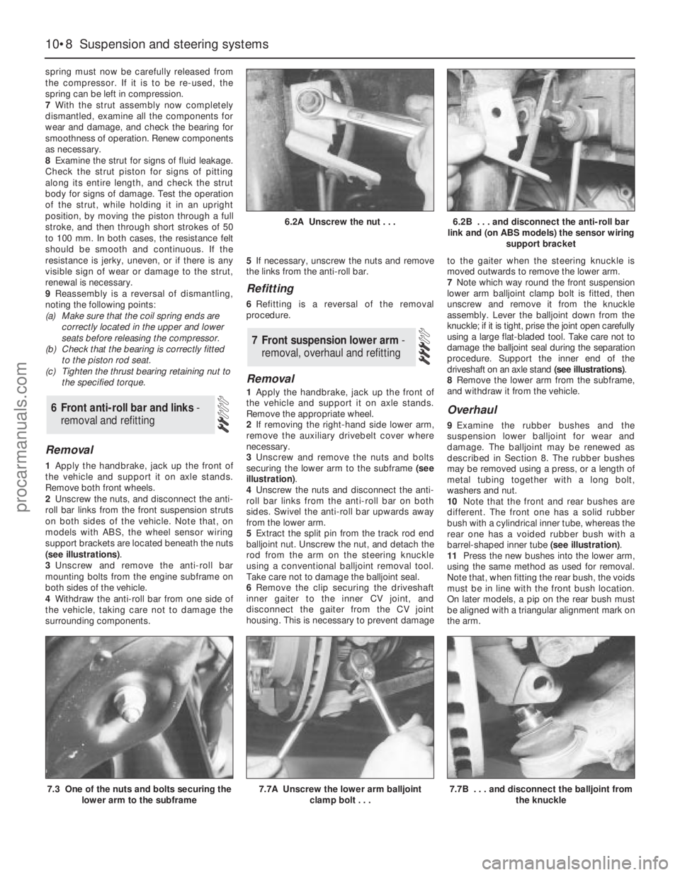
(see illustrations).
3Unscrew and remove the anti-roll bar
mounting bolts from the engine subframe on
both sides of the vehicle.
4Withdraw the anti-roll bar from one side of
the vehicle, taking care not to damage the
surrounding components.5If necessary, unscrew the nuts and remove
the links from the anti-roll bar.
Refitting
6Refitting is a reversal of the removal
procedure.
Removal
1Apply the handbrake, jack up the front of
the vehicle and support it on axle stands.
Remove the appropriate wheel.
2If removing the right-hand side lower arm,
remove the auxiliary drivebelt cover where
necessary.
3Unscrew and remove the nuts and bolts
securing the lower arm to the subframe (see
illustration).
4Unscrew the nuts and disconnect the anti-
roll bar links from the anti-roll bar on both
sides. Swivel the anti-roll bar upwards away
from the lower arm.
5Extract the split pin from the track rod end
balljoint nut. Unscrew the nut, and detach the
rod from the arm on the steering knuckle
using a conventional balljoint removal tool.
Take care not to damage the balljoint seal.
6Remove the clip securing the driveshaft
inner gaiter to the inner CV joint, and
disconnect the gaiter from the CV joint
housing. This is necessary to prevent damageto the gaiter when the steering knuckle is
moved outwards to remove the lower arm.
7Note which way round the front suspension
lower arm balljoint clamp bolt is fitted, then
unscrew and remove it from the knuckle
assembly. Lever the balljoint down from the
knuckle; if it is tight, prise the joint open carefully
using a large flat-bladed tool. Take care not to
damage the balljoint seal during the separation
procedure. Support the inner end of the
driveshaft on an axle stand (see illustrations).
8Remove the lower arm from the subframe,
and withdraw it from the vehicle.
Overhaul
9Examine the rubber bushes and the
suspension lower balljoint for wear and
damage. The balljoint may be renewed as
described in Section 8. The rubber bushes
may be removed using a press, or a length of
metal tubing together with a long bolt,
washers and nut.
10Note that the front and rear bushes are
different. The front one has a solid rubber
bush with a cylindrical inner tube, whereas the
rear one has a voided rubber bush with a
barrel-shaped inner tube (see illustration).
11Press the new bushes into the lower arm,
using the same method as used for removal.
Note that, when fitting the rear bush, the voids
must be in line with the front bush location.
On later models, a pip on the rear bush must
be aligned with a triangular alignment mark on
the arm.
7 Front suspension lower arm -
removal, overhaul and refitting
6 Front anti-roll bar and links -
removal and refitting
10•8 Suspension and steering systems
6.2A Unscrew the nut . . .6.2B . . . and disconnect the anti-roll bar
link and (on ABS models) the sensor wiring
support bracket
7.3 One of the nuts and bolts securing the
lower arm to the subframe7.7A Unscrew the lower arm balljoint
clamp bolt . . .7.7B . . . and disconnect the balljoint from
the knuckle
procarmanuals.com
Page 178 of 279
Chapter 11 Bodywork and fittings
Body side-trim mouldings and adhesive emblems - removal
and refitting . . . . . . . . . . . . . . . . . . . . . . . . . . . . . . . . . . . . . . . . . . 25
Bonnet - removal, refitting and adjustment . . . . . . . . . . . . . . . . . . . . 8
Bonnet lock - removal, refitting and adjustment . . . . . . . . . . . . . . . . 10
Bonnet release cable and lever - removal and refitting . . . . . . . . . . . 9
Boot lid - removal and refitting . . . . . . . . . . . . . . . . . . . . . . . . . . . . . 18
Boot lid lock components - removal and refitting . . . . . . . . . . . . . . . 19
Bumpers - removal and refitting . . . . . . . . . . . . . . . . . . . . . . . . . . . . 6
Central locking system components - testing, removal and refitting . 23
Centre console - removal and refitting . . . . . . . . . . . . . . . . . . . . . . . 30
Door - removal and refitting . . . . . . . . . . . . . . . . . . . . . . . . . . . . . . . 15
Door handle and lock components - removal and refitting . . . . . . . . 14
Door inner trim panel - removal and refitting . . . . . . . . . . . . . . . . . . 11
Door window glass - removal and refitting . . . . . . . . . . . . . . . . . . . . 12
Door window regulator - removal and refitting . . . . . . . . . . . . . . . . . 13
Exterior mirror and glass - removal and refitting . . . . . . . . . . . . . . . . 16
Facia - removal and refitting . . . . . . . . . . . . . . . . . . . . . . . . . . . . . . . 33
General information . . . . . . . . . . . . . . . . . . . . . . . . . . . . . . . . . . . . . . 1Glovebox - removal and refitting . . . . . . . . . . . . . . . . . . . . . . . . . . . . 32
Interior mirror - removal and refitting . . . . . . . . . . . . . . . . . . . . . . . . 17
Interior trim panels - removal and refitting . . . . . . . . . . . . . . . . . . . . 29
Maintenance - bodywork and underframe . . . . . . . . . . . . . . . . . . . . 2
Maintenance - upholstery and carpets . . . . . . . . . . . . . . . . . . . . . . . 3
Major body damage - repair . . . . . . . . . . . . . . . . . . . . . . . . . . . . . . . 5
Minor body damage - repair . . . . . . . . . . . . . . . . . . . . . . . . . . . . . . . 4
Overhead console - removal and refitting . . . . . . . . . . . . . . . . . . . . . 31
Radiator grille - removal and refitting . . . . . . . . . . . . . . . . . . . . . . . . 7
Seat belts - removal and refitting . . . . . . . . . . . . . . . . . . . . . . . . . . . 28
Seats - removal and refitting . . . . . . . . . . . . . . . . . . . . . . . . . . . . . . . 27
Sunroof - general information and adjustment . . . . . . . . . . . . . . . . . 26
Tailgate - removal and refitting . . . . . . . . . . . . . . . . . . . . . . . . . . . . . 20
Tailgate lock components - removal and refitting . . . . . . . . . . . . . . . 22
Tailgate support strut - removal and refitting . . . . . . . . . . . . . . . . . . 21
Wheel arch liner - removal and refitting . . . . . . . . . . . . . . . . . . . . . . 34
Windscreen and fixed windows - removal and refitting . . . . . . . . . . 24
Torque wrench settingsNm lbf ft
Bonnet and tailgate hinges . . . . . . . . . . . . . . . . . . . . . . . . . . . . . . . . . . . 24 18
Boot lid . . . . . . . . . . . . . . . . . . . . . . . . . . . . . . . . . . . . . . . . . . . . . . . . . . 10 7
Front seat mounting bolts . . . . . . . . . . . . . . . . . . . . . . . . . . . . . . . . . . . . 38 28
Seat belt mounting nuts and bolts . . . . . . . . . . . . . . . . . . . . . . . . . . . . . 38 28
Bumper mounting nuts . . . . . . . . . . . . . . . . . . . . . . . . . . . . . . . . . . . . . . 10 7
11•1
Easy,suitable for
novice with little
experienceFairly easy,suitable
for beginner with
some experienceFairly difficult,suitable
for competent DIY
mechanicDifficult,suitable for
experienced DIY
mechanicVery difficult,
suitable for expert DIY
or professional
Degrees of difficulty
Specifications Contents
11
The bodyshell and underframe on all
models is of all-steel welded construction,
incorporating progressive crumple zones at
the front and rear, and a rigid centre safety
cell. The bulkhead behind the engine
compartment incorporates crash grooves
which determine its energy-absorption
characteristics, and special beams to prevent
the intrusion of the front wheels into the
passenger compartment during a serious
accident. All passenger doors incorporate
side impact bars.
All sheet metal surfaces which are prone tocorrosion are galvanized. The painting
process includes a base colour which closely
matches the final topcoat, so that any stone
damage is not noticeable.
Hatchback, Saloon and Estate versions are
available. The front section of the vehicle up to
the “B” pillar is identical on all models.
Automatic seat belts are fitted to all models,
and the front seat belt stalks are mounted on
automatic tensioners (also known as
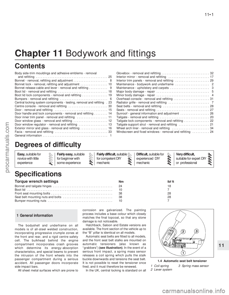
“grabbers”) (see illustration). In the event of a
serious front impact, a spring mass sensor
releases a coil spring which pulls the stalk
buckle downwards and tensions the seat belt.
It is not possible to reset the tensioner once
fired, and it must therefore be renewed.
In the UK, central locking is standard on all
1 General information
1.4 Automatic seat belt tensioner
1 Coil spring 3 Spring mass sensor
2 Lever system
procarmanuals.com
Page 179 of 279
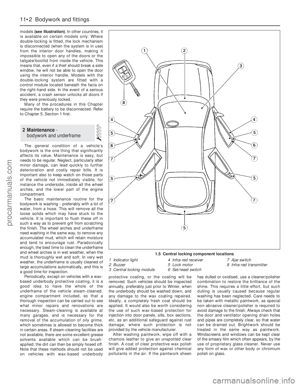
models (see illustration). In other countries, it
is available on certain models only. Where
double-locking is fitted, the lock mechanism
is disconnected (when the system is in use)
from the interior door handles, making it
impossible to open any of the doors or the
tailgate/bootlid from inside the vehicle. This
means that, even if a thief should break a side
window, he will not be able to open the door
using the interior handle. Models with the
double-locking system are fitted with a
control module located beneath the facia on
the right-hand side. In the event of a serious
accident, a crash sensor unlocks all doors if
they were previously locked.
Many of the procedures in this Chapter
require the battery to be disconnected. Refer
to Chapter 5, Section 1 first.
The general condition of a vehicle’s
bodywork is the one thing that significantly
affects its value. Maintenance is easy, but
needs to be regular. Neglect, particularly after
minor damage, can lead quickly to further
deterioration and costly repair bills. It is
important also to keep watch on those parts
of the vehicle not immediately visible, for
instance the underside, inside all the wheel
arches, and the lower part of the engine
compartment.
The basic maintenance routine for the
bodywork is washing - preferably with a lot of
water, from a hose. This will remove all the
loose solids which may have stuck to the
vehicle. It is important to flush these off in
such a way as to prevent grit from scratching
the finish. The wheel arches and underframe
need washing in the same way, to remove any
accumulated mud, which will retain moisture
and tend to encourage rust. Paradoxically
enough, the best time to clean the underframe
and wheel arches is in wet weather, when the
mud is thoroughly wet and soft. In very wet
weather, the underframe is usually cleaned of
large accumulations automatically, and this is
a good time for inspection.
Periodically, except on vehicles with a wax-
based underbody protective coating, it is a
good idea to have the whole of the
underframe of the vehicle steam-cleaned,
engine compartment included, so that a
thorough inspection can be carried out to see
what minor repairs and renovations are
necessary. Steam-cleaning is available at
many garages, and is necessary for the
removal of the accumulation of oily grime,
which sometimes is allowed to become thick
in certain areas. If steam-cleaning facilities are
not available, there are some excellent grease
solvents available which can be brush-
applied; the dirt can then be simply hosed off.
Note that these methods should not be used
on vehicles with wax-based underbodyprotective coating, or the coating will be
removed. Such vehicles should be inspected
annually, preferably just prior to Winter, when
the underbody should be washed down, and
any damage to the wax coating repaired.
Ideally, a completely fresh coat should be
applied. It would also be worth considering
the use of such wax-based protection for
injection into door panels, sills, box sections,
etc, as an additional safeguard against rust
damage, where such protection is not
provided by the vehicle manufacturer.
After washing paintwork, wipe off with a
chamois leather to give an unspotted clear
finish. A coat of clear protective wax polish
will give added protection against chemical
pollutants in the air. If the paintwork sheenhas dulled or oxidised, use a cleaner/polisher
combination to restore the brilliance of the
shine. This requires a little effort, but such
dulling is usually caused because regular
washing has been neglected. Care needs to
be taken with metallic paintwork, as special
non-abrasive cleaner/polisher is required to
avoid damage to the finish. Always check that
the door and ventilator opening drain holes
and pipes are completely clear, so that water
can be drained out. Brightwork should be
treated in the same way as paintwork.
Windscreens and windows can be kept clear
of the smeary film which often appears, by the
use of proprietary glass cleaner. Never use
any form of wax or other body or chromium
polish on glass.
2 Maintenance -
bodywork and underframe
11•2 Bodywork and fittings
1.5 Central locking component locations
1 Indicator light
2 Buzzer
3 Central locking module4 Infra-red receiver
5 Lock motor
6 Set/reset switch7 Ajar switch
8 Infra-red transmitter
procarmanuals.com
Page 206 of 279
remade, prevent the onset of corrosion in the
future by applying a coat of petroleum jelly or
silicone-based grease, or by spraying on (at
regular intervals) a proprietary ignition sealer
such as Holts Damp Start, or a water-
dispersant lubricant such as Holts Wet Start.
Note:It is important to note that the ignition
switch and the appropriate electrical circuit
must always be switched off before any of the
fuses (or relays) are removed and renewed. In
the event of the fuse/relay unit having to be
removed, the battery earth lead must be
disconnected. When reconnecting the battery,
reference should be made to Chapter 5.
1Fuses are designed to break a circuit when
a predetermined current is reached, in order
to protect components and wiring which
could be damaged by excessive current flow.
Any excessive current flow will be due to a
fault in the circuit, usually a short-circuit (see
Section 2). The main fusebox, which also
carries some relays, is located inside the
vehicle below the facia panel on the
passenger’s side, and is accessed by a lever
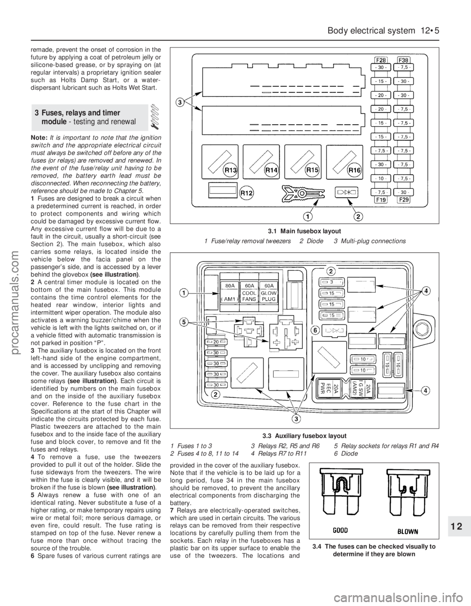
behind the glovebox (see illustration).
2A central timer module is located on the
bottom of the main fusebox. This module
contains the time control elements for the
heated rear window, interior lights and
intermittent wiper operation. The module also
activates a warning buzzer/chime when the
vehicle is left with the lights switched on, or if
a vehicle fitted with automatic transmission is
not parked in position “P”.
3The auxiliary fusebox is located on the front
left-hand side of the engine compartment,
and is accessed by unclipping and removing
the cover. The auxiliary fusebox also contains
some relays (see illustration). Each circuit is
identified by numbers on the main fusebox
and on the inside of the auxiliary fusebox
cover. Reference to the fuse chart in the
Specifications at the start of this Chapter will
indicate the circuits protected by each fuse.
Plastic tweezers are attached to the main
fusebox and to the inside face of the auxiliary
fuse and block cover, to remove and fit the
fuses and relays.
4To remove a fuse, use the tweezers
provided to pull it out of the holder. Slide the
fuse sideways from the tweezers. The wire
within the fuse is clearly visible, and it will be
broken if the fuse is blown (see illustration).
5Always renew a fuse with one of an
identical rating. Never substitute a fuse of a
higher rating, or make temporary repairs using
wire or metal foil; more serious damage, or
even fire, could result. The fuse rating is
stamped on top of the fuse. Never renew a
fuse more than once without tracing the
source of the trouble.
6Spare fuses of various current ratings areprovided in the cover of the auxiliary fusebox.
Note that if the vehicle is to be laid up for a
long period, fuse 34 in the main fusebox
should be removed, to prevent the ancillary
electrical components from discharging the
battery.
7Relays are electrically-operated switches,
which are used in certain circuits. The various
relays can be removed from their respective
locations by carefully pulling them from the
sockets. Each relay in the fuseboxes has a
plastic bar on its upper surface to enable the
use of the tweezers. The locations and
3 Fuses, relays and timer
module- testing and renewal
Body electrical system 12•5
12
3.4 The fuses can be checked visually to
determine if they are blown
3.1 Main fusebox layout
1 Fuse/relay removal tweezers 2 Diode 3 Multi-plug connections
3.3 Auxiliary fusebox layout
1 Fuses 1 to 3 3 Relays R2, R5 and R6 5 Relay sockets for relays R1 and R4
2 Fuses 4 to 8, 11 to 14 4 Relays R7 to R11 6 Diode
procarmanuals.com