1993 DODGE TRUCK transmission fluid
[x] Cancel search: transmission fluidPage 898 of 1502
•
FUEL SYSTEM
14-79
OVERDRIVE/OVERRIDE SWITCH-PCM
INPUT
The overdrive/override switch is not used with
manual transmissions. On vehicles equipped with overdrive, the PCM reg
ulates the 3-4 overdrive upshift and downshift
through the overdrive solenoid. An override switch is located on the instrument panel. The overdrive/override switch is a momentary con
tact switch. The switch contacts are normally open. When the switch is activated, the PCM will receive a ground signal. The transmission will not enter over
drive when the operator presses the override switch.
The transmission downshifts if the operator presses
the override switch while in overdrive.
COOLANT TEMPERATURE SENSOR The coolant temperature sensor is not used with
manual transmissions.
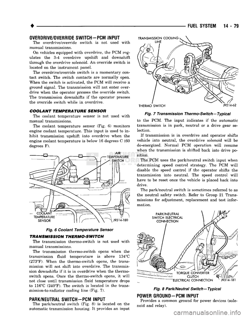
The coolant temperature sensor (Fig. 6) monitors
engine coolant temperature. This input is used to in
hibit transmission upshift into overdrive when the
engine coolant temperature is below 16 degrees C (60
degrees F).
Fig.
6 Coolant
Temperature
Sensor
TRANSMISSION THERMO-SWITCH The transmission thermo-switch is not used with
manual transmissions.
The transmission thermo-switch opens when the
transmission fluid temperature is above 134°C (273°F). When the thermo-switch opens, the trans
mission will not shift into overdrive. The transmis sion downshifts if it is in overdrive when the thermo-
switch opens. Once the thermo-switch opens, it will
not close until transmission fluid temperature drops
to 116°C (240°F). The switch is located in the trans mission-to-radiator cooling line (Fig. 7).
PARK/NEUTRAL SWITCH-PCM
INPUT
The park/neutral switch (Fig. 8) is located on the
automatic transmission housing. It provides an input
THERMO SWITCH
J9214-62
Fig.
7
Transmission
Thermo-Switch—Typical to the PCM. The input indicates if the automatic
transmission is in park, neutral or a drive gear se lection.
If transmission is in overdrive and operator shifts
vehicle into neutral, the overdrive solenoid will be de-energized. Normal PCM operation will resume
when the transmission is shifted back into drive po sition.
The PCM uses the park/neutral switch input when
determining speed control strategy. The PCM will
disable the speed control if the operator shifts the
transmission into neutral. The speed control will
have to be reset once the vehicle is placed back into drive.
The park/neutral switch is sometimes referred to as
the neutral safety switch. Refer to Group 21 Trans missions for adjustment, replacement and test infor
mation.
Fig.
8 Park/Neutral Switch—Typical
POWER
GROUND-PCM
INPUT
Provides a common ground for power devices (sole
noid and relay).
Page 906 of 1502
•
FUEL
SYSTEM
14 - 87
ENGINE
WARM-UP
• The PCM may start the air intake heater post-heat
cycle depending on intake air temperature. If manifold air temperature was at or below 15°C (59°F) when the
ignition switch was turned on, the cycle is started.
• If intake manifold air temperature is below 32°C
(90°F),
the KSB solenoid will be energized through
the air temperature switch. The solenoid remains en ergized until the air temperature switch opens. The
switch opens when intake manifold air temperature
is above 32°C (90°F).
• If the coolant temperature is below 16°C (60° F),
the transmission will not be allowed to enter over drive (automatic transmission).
• The PCM will turn on the water-in-fuel lamp if a signal is received from the water-in-fuel sensor.
CRUISE
OR
IDLE
• The PCM monitors intake manifold air tempera
ture through the charge temperature sensor input. • If intake manifold air temperature is below 32°C
(90°F),
the KSB solenoid will be energized through
the air temperature switch. The solenoid remains en ergized until the air temperature switch opens. The switch opens when intake manifold air temperature
is above 32°C (90°F).
• The air intake heater post-heat cycle will be com
pleted, if it is not already over.
• The vehicle speed sensor, engine speed sensor and
throttle position sensor inputs are used to control
transmission overdrive operation.
• If the coolant temperature is below 16° C (60° F),
the transmission will not be allowed to enter over drive (automatic transmission).
• If the transmission thermo-switch is open, the
transmission will not be allowed to enter into over
drive (automatic transmission). If the switch opens
when the vehicle is in overdrive, the transmission
will be downshifted. The transmission thermo-switch opens at 134°C (273°F).
• The thermo-switch will close once the transmission
fluid temperature drops to 116°C (240°F). • The PCM will turn on the water-in-fuel lamp if a signal is received from the water-in-fuel sensor.
ACCELERATION
• The vehicle speed sensor, engine speed sensor and
throttle position sensor inputs are used to control
transmission overdrive operation.
• If the coolant temperature is below 16° C (60° F),
the transmission will not be allowed to enter over
drive (automatic transmission).
• If intake manifold air temperature is below 32°C
(90°F),
the KSB solenoid will be energized through
the air temperature switch. The solenoid remains en ergized until the air temperature switch opens. The
switch opens when intake manifold air temperature
is above 32°C (90°F). • If the transmission thermo-switch is open, the
transmission will not be allowed to enter into over
drive (automatic transmission). If the switch opens
when the vehicle is in overdrive, the transmission
will be downshifted. The transmission thermo-switch opens at 134°C (273°F). The thermo-switch will close
once the transmission fluid temperature drops to 116°C (240°F).
• The PCM will turn on the water-in-fuel lamp if a
signal is received from the water-in-fuel sensor.
• If the speed control system resume/accelerate func
tion is being used, the PCM will only allow the vehi
cle to accelerate at a predetermined rate. If a speed
control has been set and the resume/accelerate but
ton is momentarily pushed in, the PCM will increase
vehicle speed by two miles per hour.
• If the brakes are applied, the PCM will disable the
speed control.
DECELERATION
• The vehicle speed sensor, engine speed sensor and
throttle position sensor inputs are used to control
transmission overdrive operation.
• If the coolant temperature is below 16° C (60° F),
the transmission will not be allowed to enter over drive (automatic transmission).
• If the transmission thermo-switch is open, the trans
mission will not be allowed to enter into overdrive (au
tomatic transmission). If the switch opens when the
vehicle is in overdrive, the transmission will be down shifted. The transmission thermo-switch opens at 134°C (273°F). The thermo-switch will close once the transmis
sion fluid temperature drops to 116°C (240°F).
• The PCM will turn on the water-in-fuel lamp if a
signal is received from the water-in-fuel sensor.
• If intake manifold air temperature is below 32°C
(90°F),
the KSB solenoid will be energized through
the air temperature switch. The solenoid remains en ergized until the air temperature switch opens. The
switch opens when intake manifold air temperature
is above 32°C (90°F).
• If the speed control system coast/set function is be
ing used, the PCM will only allow the vehicle to de celerate at a predetermined rate. If the coast/set
switch is pushed while the system is operating, the
PCM will set speed control to the rate the vehicle is
traveling at when the switch is released. • If the brakes are applied, the PCM will disable the speed control.
IGNITION SWITCH
OFF
• When the ignition switch is turned to the off posi
tion, the PCM still receives battery voltage through
the battery input. Battery voltage is needed to keep
PCM memory alive. The PCM memory stores diag nostic trouble code (DTC) messages and the mini
mum TPS value from the previous key-on.
Page 975 of 1502
19
- 14
STEERING
• (9) Install the fluid hoses to the power steering
pump, Tighten the pressure fitting at the pump to 30
N*m (22 ft. lbs.) torque.
(10) Install and clamp the hose on the vacuum
pump. (11) Fill the reservoir with power steering fluid
only. If necessary, refer to Pump Initial Operation
for detailed instructions.
(12) Start and run the engine. Check the operation
of the brakes, if necessary refer to Group 5, Brakes
for additional information.
PUMP REPLACEMENT—GASOLINE ENGINE
REMOVAL
WARNING:
DO NOT
REMOVE
THE
WATER PUMP COOLANT TUBE UNLESS
THE
COOLANT SYSTEM HAS BEEN DEPRESSUR1ZED
AND
DRAINED*
WARNING:
DO NOT
ATTEMPT
TO
REMOVE
THE
PUMP
WITHOUT
REMOVING
THE
BELT FIRST.
THE
AUTOMATIC TENSIONER
IS
UNDER
A
HIGH
SPRING
LOAD.
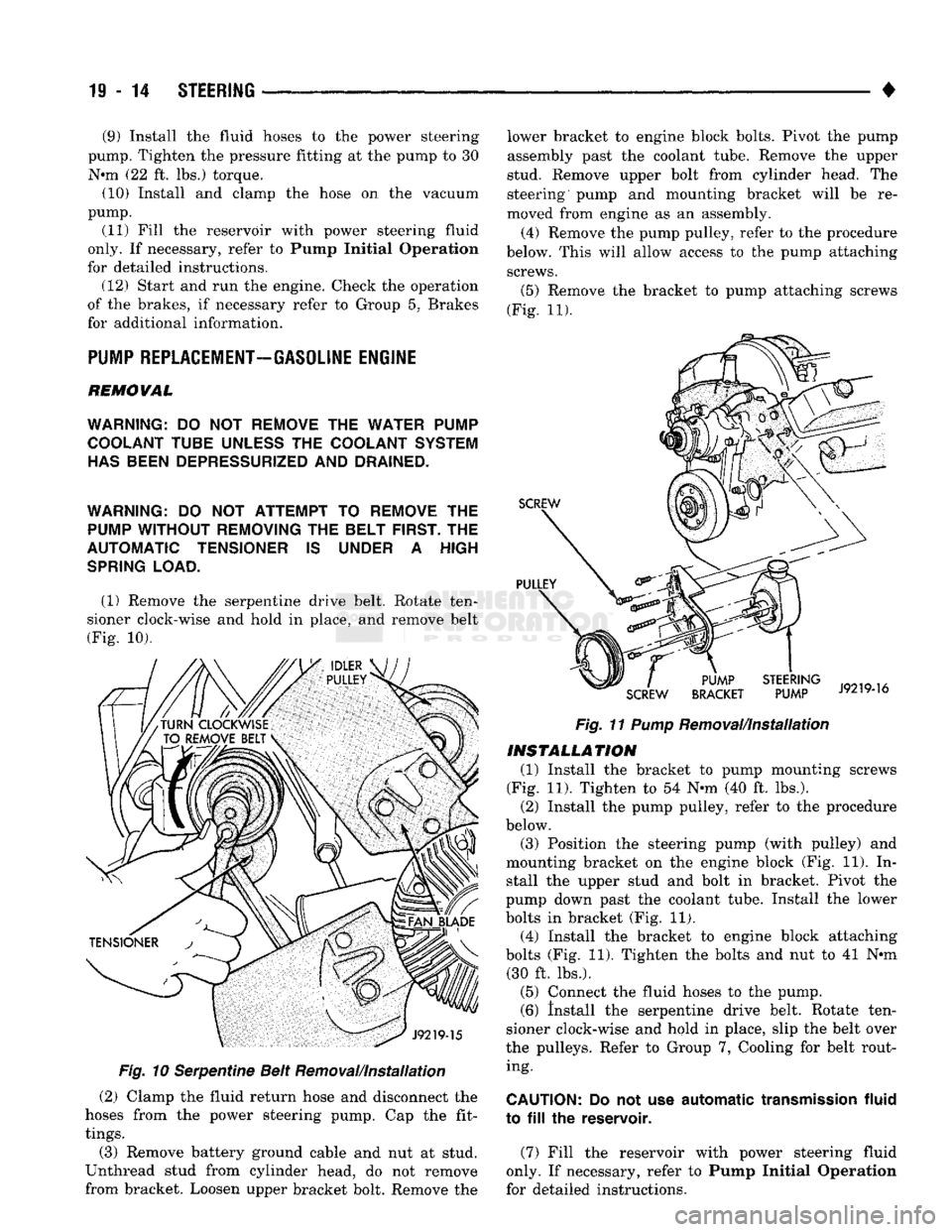
(1) Remove the serpentine drive belt. Rotate ten
sioner clock-wise and hold in place, and remove belt
(Fig. 10).
Fig.
10 Serpentine Belt Removal/Installation
(2) Clamp the fluid return hose and disconnect the
hoses from the power steering pump. Cap the fit
tings.
(3) Remove battery ground cable and nut at stud.
Unthread stud from cylinder head, do not remove
from bracket. Loosen upper bracket bolt. Remove the lower bracket to engine block bolts. Pivot the pump
assembly past the coolant tube. Remove the upper
stud. Remove upper bolt from cylinder head. The
steering pump and mounting bracket will be re
moved from engine as an assembly.
(4) Remove the pump pulley, refer to the procedure
below. This will allow access to the pump attaching screws.
(5)
Remove the bracket to pump attaching screws
(Fig. 11).
Fig.
11
Pump
Removal/Installation
INSTALLATION
(1) Install the bracket to pump mounting screws
(Fig. 11). Tighten to 54 N-m (40 ft. lbs.). (2) Install the pump pulley, refer to the procedure
below.
(3) Position the steering pump (with pulley) and
mounting bracket on the engine block (Fig. 11). In stall the upper stud and bolt in bracket. Pivot the
pump down past the coolant tube. Install the lower
bolts in bracket (Fig. 11). (4) Install the bracket to engine block attaching
bolts (Fig. 11). Tighten the bolts and nut to 41 N*m (30 ft. lbs.).
(5) Connect the fluid hoses to the pump. (6) Install the serpentine drive belt. Rotate ten
sioner clock-wise and hold in place, slip the belt over
the pulleys. Refer to Group 7, Cooling for belt rout ing.
CAUTION:
Do not use
automatic
transmission
fluid
to
fill the
reservoir.
(7) Fill the reservoir with power steering fluid
only. If necessary, refer to Pump Initial Operation
for detailed instructions.
Page 976 of 1502
#
_ ,
Fig.
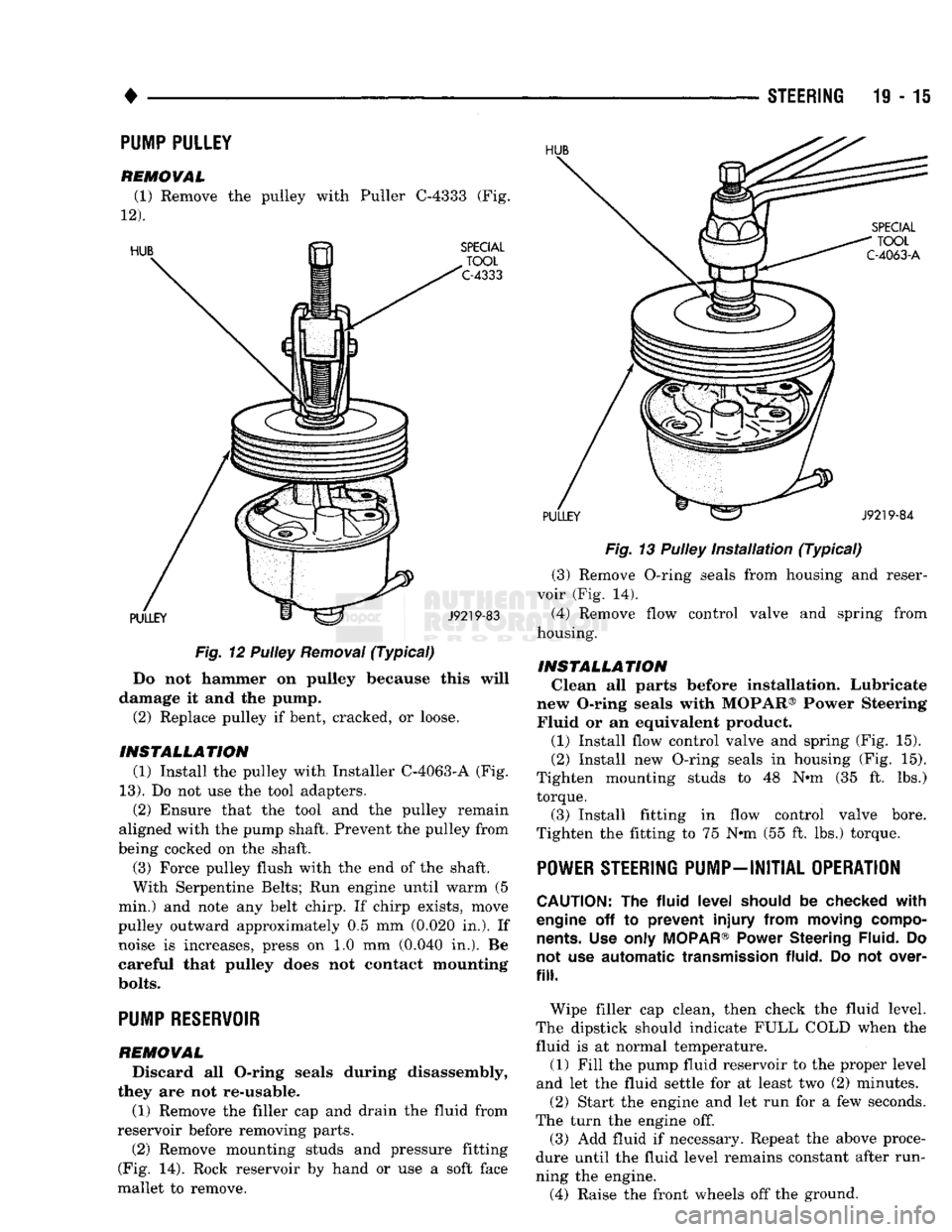
12 Pulley
Removal
(Typical)
Do not hammer on pulley because this will
damage it and the pump. (2) Replace pulley if bent, cracked, or loose.
INSTALLATION (1) Install the pulley with Installer C-4063-A (Fig.
13).
Do not use the tool adapters. (2) Ensure that the tool and the pulley remain
aligned with the pump shaft. Prevent the pulley from
being cocked on the shaft.
(3) Force pulley flush with the end of the shaft.
With Serpentine Belts; Run engine until warm (5
min.) and note any belt chirp. If chirp exists, move
pulley outward approximately 0.5 mm (0.020 in.). If noise is increases, press on 1.0 mm (0.040 in.). Be
careful that pulley does not contact mounting
bolts.
PUMP RESERVOIR
REMOVAL
Discard all O-ring seals during disassembly,
they are not re-usable.
(1) Remove the filler cap and drain the fluid from
reservoir before removing parts. (2) Remove mounting studs and pressure fitting
(Fig. 14). Rock reservoir by hand or use a soft face
mallet to remove. STEERING 19-15
Fig.
13 Pulley
Installation
(Typical)
(3) Remove O-ring seals from housing and reser
voir (Fig. 14). (4) Remove flow control valve and spring from
housing.
INSTALLATION Clean all parts before installation. Lubricate
new O-ring seals with MOPAR® Power Steering Fluid or an equivalent product.
(1) Install flow control valve and spring (Fig. 15).
(2) Install new O-ring seals in housing (Fig. 15).
Tighten mounting studs to 48 N«m (35 ft. lbs.) torque.
(3) Install fitting in flow control valve bore.
Tighten the fitting to 75 N-m (55 ft. lbs.) torque.
POWER STEERING PUMP-INITIAL OPERATION
CAUTION:
The
fluid
level
should
be
checked
with
engine
off to
prevent
injury
from
moving
compo
nents.
Use
only
MOPAR®
Power
Steering
Fluid.
Do
not
use
automatic
transmission
fluid.
Do not
over
fill.
Wipe filler cap clean, then check the fluid level.
The dipstick should indicate FULL COLD when the fluid is at normal temperature. (1) Fill the pump fluid reservoir to the proper level
and let the fluid settle for at least two (2) minutes. (2) Start the engine and let run for a few seconds.
The turn the engine off. (3) Add fluid if necessary. Repeat the above proce
dure until the fluid level remains constant after run
ning the engine. (4) Raise the front wheels off the ground.
PUMP PULLEY
REMOVAL
(1) Remove the pulley with Puller C-4333 (Fig.
12).
Page 1004 of 1502
•
NV4500 MANUAL
TRANSMISSION
21 - 3
PTO
COVER
J9221-14
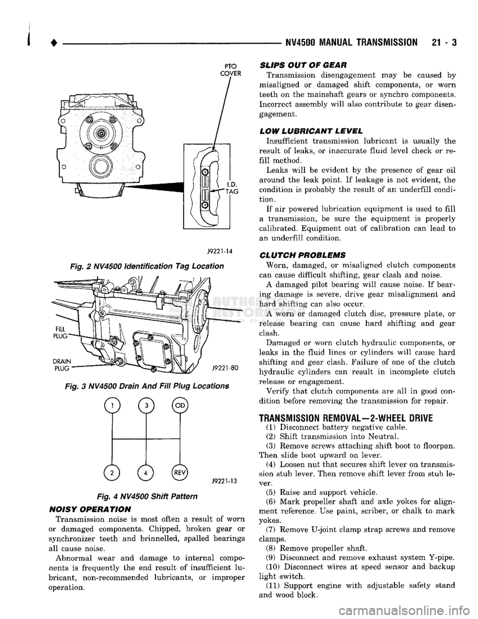
Fig. 2 NV4500 identification Tag Location
DRAIN
PLUG
J9221-80
Fig. 3 NV4500 Drain And Fill Plug Locations
o
0 ©
0 0©
J9221-13
Fig. 4 NV4500 Shitt Pattern
NOISY OPERATION Transmission noise is most often a result of worn
or damaged components. Chipped, broken gear or
synchronizer teeth and brinnelled, spalled bearings
all cause noise.
Abnormal wear and damage to internal compo
nents is frequently the end result of insufficient lu
bricant, non-recommended lubricants, or improper operation.
SLIPS
OUT OF
GEAR
Transmission disengagement may be caused by
misaligned or damaged shift components, or worn
teeth on the mainshaft gears or synchro components. Incorrect assembly will also contribute to gear disengagement.
LOW LUBRICANT LEWEL
Insufficient transmission lubricant is usually the
result of leaks, or inaccurate fluid level check or re
fill method.
Leaks will be evident by the presence of gear oil
around the leak point. If leakage is not evident, the
condition is probably the result of an underfill condi
tion.
If air powered lubrication equipment is used to fill
a transmission, be sure the equipment is properly
calibrated. Equipment out of calibration can lead to
an underfill condition.
CLUTCH
PROBLEMS
Worn, damaged, or misaligned clutch components
can cause difficult shifting, gear clash and noise.
A damaged pilot bearing will cause noise. If bear
ing damage is severe, drive gear misalignment and
hard shifting can also occur.
A worn or damaged clutch disc, pressure plate, or
release bearing can cause hard shifting and gear clash.
Damaged or worn clutch hydraulic components, or
leaks in the fluid lines or cylinders will cause hard shifting and gear clash. Failure of one of the clutch
hydraulic cylinders can result in incomplete clutch release or engagement.
Verify that clutch components are all in good con
dition before removing the transmission for repair.
TRANSMISSION
REMOVAL—2-WHEEL DRIVE
(1) Disconnect battery negative cable. (2) Shift transmission into Neutral.
(3) Remove screws attaching shift boot to floorpan.
Then slide boot upward on lever. (4) Loosen nut that secures shift lever on transmis
sion stub lever. Then remove shift lever from stub le
ver. (5) Raise and support vehicle.
(6) Mark propeller shaft and axle yokes for align
ment reference. Use paint, scriber, or chalk to mark
yokes.
(7) Remove U-joint clamp strap screws and remove
clamps. (8) Remove propeller shaft.
(9) Disconnect and remove exhaust system Y-pipe.
(10) Disconnect wires at speed sensor and backup
light switch. (11) Support engine with adjustable safety stand
and wood block.
Page 1074 of 1502
•
AUTOMATIC
TRANSMISSION—32RH/36RH/37RH/42RH/46RH
21 - 73
CONTENTS
page
AUTOMATIC TRANSMISSION DIAGNOSIS AND TESTING
85
AUTOMATIC TRANSMISSION REMOVAL AND INSTALLATION
142
GENERAL
INFORMATION-32RH/36RH/37RH
... 73
GENERAL
INFORMATION-42RH/46RH
78
IN-VEHICLE SERVICE—32RH/36RH/37RH/
42RH/46RH
130
page
OVERDRIVE
UNIT
OVERHAUL—42RH/46RH
. 324
TRANSMISSION OVERHAUL—32RH
152
TRANSMISSION
OVERHAUL—36RH/37RH
.. 192
TRANSMISSION OVERHAUL—42RH
233
TRANSMISSION OVERHAUL—46RH
278
GENERAL IN FORMATION-32RH/36RH/37RH INDEX
page
Components Unique
to
37RH
Diesel Transmission
76
Description
73
Recommended
Fluid
76
page
Torque Converter
76
Transmission Hydraulic
Control
System
76
Transmission
Identification 76
DESCRIPTION
Chrysler 32RH/36RH/37RH transmissions are
three speed, fully automatic units with a planetary
gear system (Figs. 1 and 2). The 32RH transmission is used with 3.9L and 5.2L
engines. The 36RH transmission is used with 5.2IV 5.9L gas engines. The 37RH is used with the 5.9L
Cummins diesel engine.
AUTOMATIC TRANSMISSION-32RH/36RH/37RH/42RH/46RH
Page 1077 of 1502
21 - 76
AUTOMATIC
TRANSMISSION—32RH/36RH/37RH/42RH/46RH
•
TORQUE
CONVERTER
A three element torque converter is used. The con
verter used with 32RH and some 36RH transmis sions has a modulated converter clutch. The
converter used with 37RH transmissions is not
equipped with a modulated clutch. The converter used with 1993, 32RH transmissions
is new. The converter hub was changed to accept the
new style drive flats on the oil pump inner gear. The
new style converter is not interchangeable with pre
vious designs. A 241 or 273 mm (9.5 or 10.75 in.) converter is
used for 3.9L, 5.2L and 5.9L gas engine applications.
A 310 mm (12.2 in.) converter is used for diesel en
gine applications. The converter impeller is connected to the engine
crankshaft through the front cover which is welded
to the impeller. The turbine is splined to the trans
mission input shaft and the stator is splined to the transmission reaction shaft. The converter is a welded assembly. It is not a re
pairable component and is serviced as an assembly.
RECOMMENDED
FLUID
The recommended and preferred fluid for Chrysler
automatic transmissions is Mopar ATF Plus, Type
7176.
Use Mopar Dexron II only when ATF Plus is
not readily available.
TRANSMISSION
IDENTIFICATION
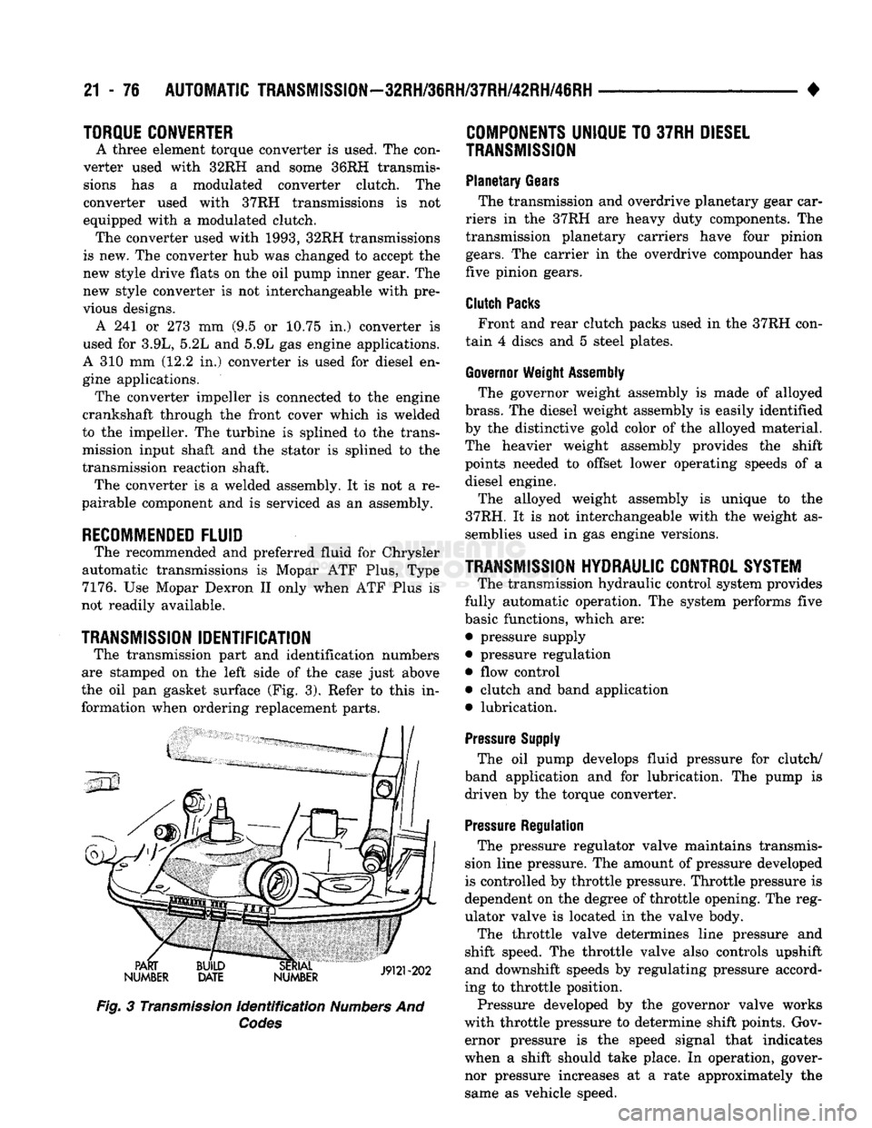
The transmission part and identification numbers
are stamped on the left side of the case just above
the oil pan gasket surface (Fig. 3). Refer to this in formation when ordering replacement parts.
PART
NUMBER BUILD
DATE SERIAL
19191-909
NUMBER JVUI zuz
Fig.
3
Transmission
Identification
Numbers
And
Codes
COMPONENTS
UNIQUE
TO
37RH
DIESEL
TRANSMISSION
Planetary
Gears
The transmission and overdrive planetary gear car
riers in the 37RH are heavy duty components. The
transmission planetary carriers have four pinion
gears.
The carrier in the overdrive compounder has
five pinion gears.
Clutch
Packs
Front and rear clutch packs used in the 37RH con
tain 4 discs and 5 steel plates.
Governor
Weight
Assembly
The governor weight assembly is made of alloyed
brass.
The diesel weight assembly is easily identified
by the distinctive gold color of the alloyed material.
The heavier weight assembly provides the shift
points needed to offset lower operating speeds of a diesel engine.
The alloyed weight assembly is unique to the
37RH. It is not interchangeable with the weight as semblies used in gas engine versions.
TRANSMISSION
HYDRAULIC
CONTROL
SYSTEM
The transmission hydraulic control system provides
fully automatic operation. The system performs five
basic functions, which are: • pressure supply
• pressure regulation • flow control
• clutch and band application
• lubrication.
Pressure
Supply
The oil pump develops fluid pressure for clutch/
band application and for lubrication. The pump is driven by the torque converter.
Pressure
Regulation
The pressure regulator valve maintains transmis
sion line pressure. The amount of pressure developed
is controlled by throttle pressure. Throttle pressure is
dependent on the degree of throttle opening. The reg
ulator valve is located in the valve body.
The throttle valve determines line pressure and
shift speed. The throttle valve also controls upshift
and downshift speeds by regulating pressure accord
ing to throttle position.
Pressure developed by the governor valve works
with throttle pressure to determine shift points. Gov ernor pressure is the speed signal that indicates
when a shift should take place. In operation, gover
nor pressure increases at a rate approximately the same as vehicle speed.
Page 1078 of 1502
•
AUTOMATIC
TRANSMISSION—32RH/3SRH/37RH/42RH/48RH
21 - 77
Flow
Control And Lubrication
The manual valve is operated by the gearshift link
age and provides the operating range selected by the
driver.
The 1-2 shift valve provides automatic 1-2 or 2-1
shifts and the 2-3 shift valve provides automatic 2-3
or 3-2 shifts.
The kickdown valve provides forced 3-2 or 3-1
downshifts depending on vehicle speed. Downshifts
occur when the throttle is opened beyond downshift
detent position which is just before wide open throt
tle.
The 2-3 valve throttle pressure plug provides 3-2
downshifts with varying throttle openings and de
pending on vehicle speed.
The 1-2 shift control valve transmits 1-2 shift pres
sure to the accumulator piston to control kickdown
band capacity on 1-2 upshifts and 3-2 downshifts.
The limit valve determines maximum speed at
which a 3-2 part throttle kickdown can be made. Some transmissions do not have the limit valve and
maximum speed for a 3-2 kickdown is at the detent
position.
The shuttle valve has two functions. First is fast
front band release and smooth engagement during "lift foot" 2-3 upshifts. Second is to regulate front
clutch release and band application during 3-2 down
shifts.
The converter clutch valve applies the converter
modulated clutch when supplied with line pressure through the converter clutch solenoid. The solenoid is
controlled by and connected to the powertrain control module through a connector in the transmission case.
Electronic control of converter clutch engagement
includes disengagement at closed throttle during
warmup and during part throttle acceleration. Non- converter clutch transmissions have a threaded plug at the rear of the transmission case in place of the
solenoid wiring connector.
The fail safe valve restricts feed to the converter
clutch if front clutch pressure drops. It permits clutch
engagement only in direct (third) gear and provides
fast clutch release during kickdown.
The switch valve directs apply fluid pressure to the
converter clutch in one position and releases it in the
opposite position. It also directs oil to the cooling and
lube circuits. The switch valve regulates oil pressure
to the torque converter by limiting maximum oil
pressure to 130 psi.
Clutch/Band
Application The front/rear clutch pistons and servo pistons are
actuated by line pressure. When line pressure is re
moved, the pistons are released by spring tension.
On 2-3 upshifts, the front servo piston is released
by spring tension and hydraulic pressure. The accu mulator controls hydraulic pressure on the apply side
of the front servo during 1-2 upshifts and at all
throttle openings.