1993 DODGE TRUCK engine oil
[x] Cancel search: engine oilPage 140 of 1502
•
REAR
SUSPENSION
AND
AXLE
3 - 11 8 3/8 and 9 1/4
AXLE
INDEX
page
Axle Shaft, Seal
and
Bearing Service
......... 11
Complete Axle Removal/Installation
16
Differential
Service
16
Information
11
INFORMATION
The 8 3/8 and 9 1/4 axle (Fig. 1) housing consist of
a cast iron center section. They also have two steel
axle shaft tubes that are pressed into and welded to
the differential housing. The removable, stamped steel cover provides a
means for inspection and service without removing
the complete axle from the vehicle.
LUBRICANT
Multi-purpose, hypoid gear lubricant should be
used for 8 3/8 and 9 1/4 axles. The lubricant should
have MIL-L-2105C and API GL 5 quality specifica
tions.
MOPAR® Hypoid Gear Lubricant conforms to
both of these specifications.
Refer to Group 0, Lubrication and Maintenance for
additional information.
CAUTION:
If a
rear axle
is
submerged
in
water,
the
axle lubricant must
be
replaced immediately.
DRAIN
AND
REFILL
(1) Drive the vehicle until the gear lubricant
reaches normal operating temperature.
(2) Raise and support the vehicle.
(3) Remove the lubricant fill hole plug from the
differential housing cover.
(4) Remove the differential housing cover. Allow
the original lubricant to completely drain from the
housing and axle shaft tubes. (5) With standard differential, clean the differen
tial and the housing cavity with a flushing oil (or light engine oil). This will remove the residual lubri
cant and foreign matter.Do not use water, steam,
kerosene or gasoline for flushing.
CAUTION:
DO NOT
FLUSH
Sure-Grip differentials.
Sure-Grip
differentials
may be
cleaned only
by
wip
ing
with
clean,
lint-free
cloths.
(6)
Scrape the residual sealant from the housing
and cover mating surfaces. Clean the mating sur
faces with mineral spirits. Apply a bead of MOPAR® Silicone Rubber Sealant on the housing cover (Fig.
2).
Allow the sealant to cure for a few minutes.
page
Lubricant
11
Pinion Depth Measurement
and
Adjustment
with
Gauge
Set 20
Pinion
Seal
Replacement
14
Install the housing cover within 5 minutes af
ter applying the sealant. If not installed, the sealant must be removed and another bead ap
plied. (7) Install the cover on the differential. Install the
identification tag. Tighten the cover bolts to 47 N#m (35 ft. lbs.) torque.
CAUTION:
Overfilling
the
differential
can
result
in
the lubricant foaming
and
overheating.
(8) Refill the differential with the specified quan
tity of MOPAR® Hypoid Gear Lubricant. With Sure- Grip differentials, add a container of MOPAR®
Hypoid Gear Lubricant Additive.
(9) Install the fill hole plug.
(10) Road test the vehicle.
AXLE
SHAFT, SEAL AND BEARING
SERVICE
CAUTION:
When rear axle service
is
necessary, both rear wheels must
be
raised
off the
surface
so
that
they
are
free
to
rotate.
Be
cautious when
the
tires
are
being rotated
by the
engine
or by
other
means.
CAUTION:
If
equipped
with
a
Sure-Grip
differential,
do
not
rotate
either
axle shaft unless both
are
prop
erly
in-place. Rotation
of one
axle shaft without
the
other being installed
can
result
in
misalignment
of
the side gears/splines. This
will
necessitate side
gear
re-alignment before
the
axle shaft
can be in
stalled.
AXLE SHAFT REMOVAL
(1) Raise and support the vehicle.
(2) Remove the wheel.
(3) Remove the brake drum.
(4) Clean all the foreign material from housing
cover area.
(5) Loosen the housing cover bolts. Drain the lubri
cant from the housing. Remove the housing cover.
(6)
Rotate the differential case so the pinion mate
gear shaft lock screw is accessible. Remove the lock screw and the pinion mate gear shaft from the case (Fig. 3).
Page 155 of 1502
3
- 28
REAR
SUSPENSION
AND
AXLE
•
SURE-GRIP
DIFFERENTIAL
SERVICE
GENERAL
INFORMATION
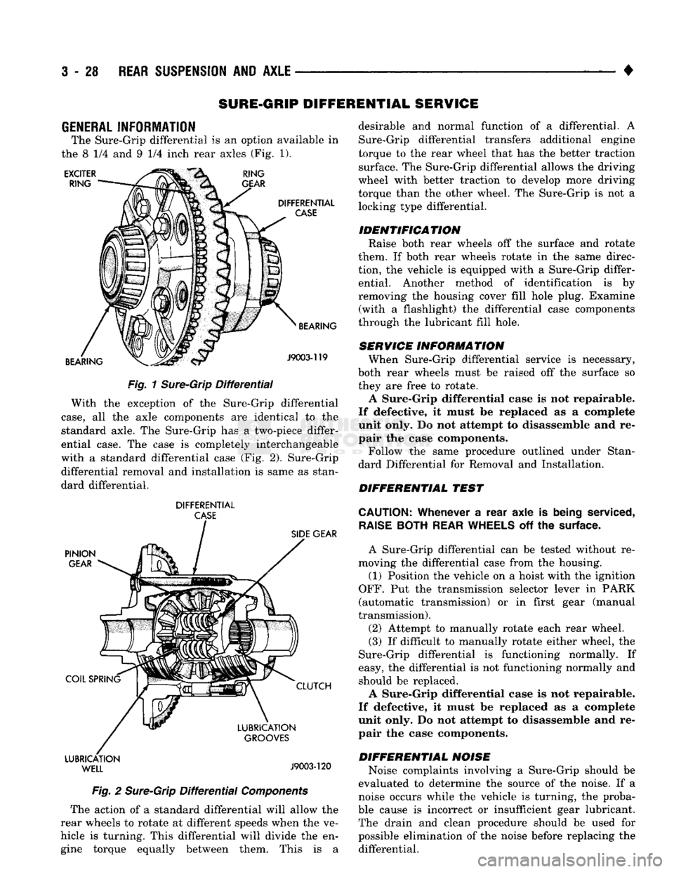
The Sure-Grip differential
is an
option available
in
the
8 1/4 and 9 1/4
inch rear axles
(Fig. 1).
EXCITER
RING RING
GEAR
DIFFERENTIAL
CASE
BEARING BEARING
J9003-119
Fig.
1
Sure-Grip
Differential
With
the
exception
of the
Sure-Grip differential
case,
all the
axle components
are
identical
to the
standard axle.
The
Sure-Grip
has a
two-piece differ
ential case.
The
case
is
completely interchangeable
with
a
standard differential case
(Fig. 2).
Sure-Grip differential removal
and
installation
is
same
as
stan
dard differential.
DIFFERENTIAL
CASE
PINION
GEAR
COIL SPRING LUBRICATION
WELL
SIDE
GEAR
CLUTCH
LUBRICATION
GROOVES
J9003-120
Fig.
2
Sure-Grip
Differential
Components
The action
of a
standard differential will allow
the
rear wheels
to
rotate
at
different speeds when
the ve
hicle
is
turning. This differential will divide
the en
gine torque equally between them. This
is a
desirable
and
normal function
of a
differential.
A
Sure-Grip differential transfers additional engine
torque
to the
rear wheel that
has the
better traction surface.
The
Sure-Grip differential allows
the
driving
wheel with better traction
to
develop more driving
torque than
the
other wheel.
The
Sure-Grip
is not a
locking type differential.
IDENTIFICATION Raise both rear wheels
off the
surface
and
rotate
them.
If
both rear wheels rotate
in the
same direc
tion,
the
vehicle
is
equipped with
a
Sure-Grip differ ential. Another method
of
identification
is by
removing
the
housing cover fill hole plug. Examine (with
a
flashlight)
the
differential case components
through
the
lubricant fill hole.
SERVICE INFORMATION When Sure-Grip differential service
is
necessary,
both rear wheels must
be
raised
off the
surface
so
they
are
free
to
rotate.
A Sure-Grip differential case
is not
repairable.
If defective,
it
must
be
replaced
as a
complete
unit only.
Do not
attempt
to
disassemble
and re
pair
the
case components.
Follow
the
same procedure outlined under Stan
dard Differential
for
Removal
and
Installation.
DIFFERENTIAL TEST
CAUTION:
Whenever
a
rear axle
is
being
serviced,
RAISE
BOTH
REAR
WHEELS
off the
surface.
A Sure-Grip differential
can be
tested without
re
moving
the
differential case from
the
housing.
(1) Position
the
vehicle
on a
hoist with
the
ignition
OFF.
Put the
transmission selector lever
in
PARK
(automatic transmission)
or in
first gear (manual
transmission).
(2) Attempt
to
manually rotate each rear wheel.
(3)
If
difficult
to
manually rotate either wheel,
the
Sure-Grip differential
is
functioning normally.
If
easy,
the
differential
is not
functioning normally
and
should
be
replaced.
A Sure-Grip differential case
is not
repairable.
If defective,
it
must
be
replaced
as a
complete
unit only.
Do not
attempt
to
disassemble
and re
pair
the
case components.
DIFFERENTIAL NOISE Noise complaints involving
a
Sure-Grip should
be
evaluated
to
determine
the
source
of the
noise.
If a
noise occurs while
the
vehicle
is
turning,
the
proba
ble cause
is
incorrect
or
insufficient gear lubricant. The drain
and
clean procedure should
be
used
for
possible elimination
of the
noise before replacing
the
differential.
Page 160 of 1502
•
REAR
SUSPENSION
AND
AXLE
3 - 33
WHEEL BEARING SERVICE
REMOVAL (1) Remove the axle shaft, refer to the removal
procedure. (2) Remove the nut lock and adjustment nut.
(3) Remove the hub and drum assembly. The outer
wheel bearing will slide out as the hub is being re
moved. (4) Place hub on bench and remove inner grease
seal. Discard seal. (5) Remove inner wheel bearing. Inspect wheel
bearings for wear. Replace as necessary.
CLEANING AND INSPECTION (1) Thoroughly clean both wheel bearings and in
terior of the hub. Remove all of the residual lubri cant. (2) To clean the bearings:
• Soak them in an appropriate cleaning solvent
• Strike the flat of each bearing against a hardwood
block several times • Flush bearing between strikes
• Repeat the procedure above until each bearing is clean
• Dry the bearings with compressed air but do not
spin them (3) After cleaning, apply engine oil to each bear
ing. (4) Rotate each bearing slowly while applying
downward force. Examine the rollers for pitting and
roughness. Replace worn or otherwise defective bear
ings.
If a bearing has pitted and/or rough surfaced
rollers, replace both the bearing and bearing cup. (5) If reusable, remove the engine oil from each
bearing. Pack each bearing with multi-purpose
NLGI, grade 2, EP-type lubricant. Ensure that lubricant is forced into all the cav
ities between the bearing cage and rollers.
INSTALLATION (1) If a bearing and cup must be replaced, remove
the cup from the hub bore. Use a brass drift or an appropriate removal tool to tap out the cup. (2) Install the replacement bearing cup(s) with an
appropriate installation tool.
(3) Apply lubricant to surface area of the hub bore.
Install the inner wheel bearing in the hub. Install a
replacement bearing seal with an appropriate seal installation tool. (4) Inspect the bearing and seal contact surfaces on
the axle for burrs and/or roughness.
(5) Remove all the rough contact surfaces from the
axle.
Apply a coating of multi-purpose NLGI, grade
2,
EP-type lubricant to the axle.
CAUTION:
Use care to prevent the inner
wheel
bear
ing
and bearing
seal
from contacting the axle
threads
during installation. Otherwise, the
threads,
bearing,
and
seal
could
be
damaged.
(6) Carefully slide the hub onto the axle. Install
the outer wheel bearing, the locktab and outer wheel
bearing locknut.
(7) Tighten the adjustment nut to 163-190 Nnn
(120-140 ft. lbs.) torque while rotating the wheel. (8) Loosen the adjustment nut 1/3 of-a-turn (120
degrees) to provide 0.001-inch to 0.008-inch wheel
bearing end play.
(9) Tap the nut lock into the spindle keyway and
adjustment nut.
(10) Install the axle shaft, refer to the installation
procedure.
COMPLETE AXLE REMOVAL/INSTALLATION
REMOVAL It is not necessary to remove the complete axle
from the vehicle for routine or differential service. If
the differential housing or axle shaft tubes are dam aged, the complete axle can be removed and in
stalled.
(1) Raise the rear of the vehicle until the rear
wheels are not contacting the surface. Support the
vehicle body at the front of the rear springs.
(2) Use a wooden block to retain the brake pedal
in the up position.
(3) Remove the axle shafts, wheels, hubs and
brake drums. If necessary, refer to the applicable re moval procedures.
(4) Disconnect the brake line and cap the fittings
to prevent loss of brake fluid. (5) Disconnect the parking brake cables.
Scribe installation alignment reference marks
on drive shaft U-joint and on pinion yoke. (6) Disconnect the drive shaft U-joint from the pin
ion yoke. Secure it in an upright position to prevent
damage to the U-joint.
(7) Remove the rear shock absorbers and the rear
spring U-bolts from the axle. (8) Remove the rear axle from the vehicle.
INSTALLATION (1) If the differential housing cover was removed,
ensure differential housing and cover mating sur
faces are clean.
(2) If cover was removed, apply a bead of MOPAR
Silicone Rubber Sealant around the cover bolt circle.
Install the differential housing cover. Tighten the
cover bolts to 47 N»m (35 ft. lbs.) torque. Install the axle gear ratio identification tag under one of
the cover bolts.
(3) With the vehicle body supported at the front of
the rear springs, position the axle under the rear springs.
Page 190 of 1502

•
BRAKES
i - 3 BRAKE DIAGNOSIS
INDEX
page
Brake
Warning Lights
3
Diagnosing
Brake Problems .................
4
Diagnosis
Procedures
3
Low
Vacuum
Switch—Diesel
Models
3
page
Master
Cylinder/Power Booster Test
5
Power
Booster
Check
Valve Test .............
6
Power
Booster
Vacuum
Test .................
6
Testing Diesel
Engine
Vacuum
Pump
Output
.... 6
DIAGNOSIS
PROCEDURES
Brake diagnosis involves determining
if the
prob
lem
is
related
to a
mechanical, hydraulic
or
vacuum
operated component.
A
preliminary check, road test
ing
and
component inspection
can all be
used
to de
termine
a
problem cause. Road testing will either verify proper brake opera
tion
or
confirm
the
existence
of a
problem. Compo nent inspection will,
in
most cases, identify
the
actual part causing
a
problem. The first diagnosis step
is the
preliminary check. This
involves inspecting fluid level, parking brake action,
wheel
and
tire condition, checking
for
obvious leaks
or
component damage
and
testing brake pedal response. A road test will confirm
the
existence
of a
problem.
Final diagnosis procedure involves road test analysis and
a
visual inspection
of
brake components.
BRAKE
WARNING LIGHTS
The
red
brake warning light
is
connected
to the
parking brake switch
and to the
pressure differential switch
in the
combination valve. The
red
light will illuminate when
the
parking
brakes
are
applied
or
when
a
fluid pressure drop
oc
curs
in the
front
or
rear brake circuit.
The
light will
also illuminate
for
approximately
2-4
seconds
at en
gine start
up.
This
is a
self test feature designed
to
check bulb
and
circuit operation each time
the en
gine
is
started. The amber antilock light
is
connected
to the
anti-
lock rear brake hydraulic valve.
The
light will illu
minate
if a
fault occurs within
the
antilock system.
LOW VACUUM SWITCH-DIESEL MODELS
On diesel models,
the red
brake warning light
is
also
used
to
alert
the
driver
of a low
brake booster vacuum
condition.
The
warning light
is in
circuit with
a
vacuum
warning switch mounted
on the
driver side fender
panel.
The
vacuum side
of the
switch
is
connected
to the
power brake booster.
The
electrical side
of the
switch
is
connected
to the
brake warning light. The
low
vacuum switch monitors booster vacuum
level whenever
the
engine
is
running.
If
booster vac
uum falls below
8.5
inches vacuum
for a
minimum
of
10 seconds,
the
switch completes
the
circuit
to the
warning light causing
it to
illuminate.
The
warning light
is
designed
to
differentiate between
a low
vac
uum condition
and a
hydraulic circuit fault.
PRELIMINARY
BRAKE CHECK
(1) Check condition
of
tires
and
wheels. Damaged
wheels
and
worn, damaged,
or
underinflated tires
can
cause pull, shudder, tramp,
and a
condition similar
to
grab.
(2)
If
complaint
was
based
on
noise when braking,
check suspension components. Jounce front
and
rear
of
vehicle
and
listen
for
noise that might
be
caused
by
loose, worn
or
damaged suspension
or
steering compo
nents.
(3) Inspect brake fluid level
and
condition. Note
that
the
front disc brake reservoir fluid level will drop
in
proportion
to
normal lining wear. Also note
that brake fluid tends
to
darken over time. This
is normal
and
should
not be
mistaken
for
con
tamination.
If the
fluid
is
still clear
and
free
of
foreign material,
it is OK.
(a)
If
fluid level
is
abnormally
low,
look
for
evi
dence
of
leaks
at
calipers, wheel cylinders, brake-
lines
and
master cylinder.
(b)
If
fluid appears contaminated, drain
out a
sample.
If
fluid
is
separated into layers,
or
obvi
ously contains
oil or a
substance other than brake
fluid,
the
system seals
and
cups will have
to be re
placed
and the
hydraulic system flushed.
(4) Check parking brake operation. Verify free
movement
and
full release
of
cables
and
pedal. Also
note
if
vehicle
was
being operated with parking
brake partially applied.
(5) Check brake pedal operation. Verify that pedal
does
not
bind
and has
adequate free play.
If
pedal
lacks free play, check pedal
and
power booster
for be
ing loose
or for
bind condition.
Do not
road test until
condition
is
corrected.
(6)
If
components checked appear
OK,
road test
the
vehicle.
ROAD
TESTING (1)
If
complaint involved
low
brake pedal, pump
the pedal
and
note
if the
pedal comes back
up to
nor mal height.
(2) Check brake pedal response with transmission
in Neutral
and
engine running. Pedal should remain
firm under steady foot pressure.
Page 192 of 1502

•
BRAKES
5 - 5 Disc brake rotors with excessive lateral runout or
thickness variation, or out of round brake drums are
the primary causes of pulsation. Other causes are loose
wheel bearings or calipers and worn, damaged tires.
PULL A
front pull condition could be the result of con
taminated lining in one caliper, seized caliper piston,
binding caliper, loose caliper, loose or corroded slide
pins,
improper brakeshoes, or a damaged rotor.
A worn, damaged wheel bearing or suspension compo
nent are further causes of pull. A damaged front tire (bruised, ply separation) can also cause pull.
A common and frequently misdiagnosed pull condi
tion is where direction of pull changes after a few
stops.
The cause is a combination of brake drag fol
lowed by fade at one of the brake units.
As the dragging brake overheats, efficiency is so
reduced that fade occurs. Since the opposite brake
unit is still functioning normally, its braking effect is
magnified. This causes pull to switch direction in fa
vor of the normally functioning brake unit.
When diagnosing a change in pull condition, re
member that pull will return to the original direction
if the dragging brake unit is allowed to cool down (and is not seriously damaged).
REAR BRAKE GRAB
OR
PULL
Rear grab or pull is usually caused by an improperly
adjusted or seized parking brake cable, contaminated
lining, bent or binding shoes and support plates, or im
properly assembled components. This is particularly
true when only one rear wheel is involved. However,
when both rear wheels are affected, the master cylinder or proportioning valve could be at fault.
BRAKES
DO NOT
HOLD
AFTER
DRIVING
THROUGH
DEEP
WATER
PUDDLES
This condition is generally caused by water soaked
lining. If the lining is only wet, it can be dried by driv
ing with the brakes very lightly applied for a few min
utes.
However, if the lining is thoroughly wet and dirty,
disassembly and cleaning will be necessary.
BRAKE NOISE
Squeak/Squeal
Brake squeak or squeal may be due to linings that
are wet or contaminated with brake fluid, grease, or oil. Glazed linings and rotors with hard spots can also con
tribute to squeak. Dirt and foreign material embedded in the brake lining can also cause squeak/squeal.
A very loud squeak or squeal is frequently a sign of
severely worn brake lining. If the lining has worn
through to the brakeshoes in spots, metal-to-metal con
tact occurs. If the condition is allowed to continue, ro tors can become so scored that replacement is necessary.
Thump/Clunk
Thumping or clunk noises during braking are fre
quently not caused by brake components. In many
cases,
such noises are caused by loose or damaged steering, suspension, or engine components. How
ever, calipers that bind on the slide pins, or slide sur
faces,
can generate a thump or clunk noise. Worn
out, improperly adjusted, or improperly assembled
rear brakeshoes can also produce a thump noise.
Chatter
Brake chatter is usually caused by loose or worn
components, or glazed/burnt lining. Rotors with hard
spots can also contribute to chatter. Additional
causes of chatter are out of tolerance rotors, brake
lining not securely attached to the shoes, loose wheel
bearings and contaminated brake lining.
Brakelining Contamination Brakelining contamination is usually a product of
leaking calipers or wheel cylinders, driving through
deep water puddles, or lining that has become cov
ered with grease and grit during repair.
Wheel and
Tire
Problems Some conditions attributed to brake components
may actually be caused by a wheel or tire problem.
A damaged wheel can cause shudder, vibration and
pull. A worn or damaged tire can also cause pull.
Severely worn tires with very little tread left can
produce a grab-like condition as the tire loses and re covers traction. Flat-spotted tires can cause vibration and wheel
tramp and generate shudder during brake operation. A tire with internal damage such as a severe
bruise or ply separation can cause pull and vibration.
MASTER
CYLINDER/POWER BOOSTER TEST
(1) Start engine and check booster vacuum hose
connections. Hissing noise indicates a vacuum leak. Correct any leaks before proceeding. (2) Stop engine and shift transmission into Neu
tral (3) Pump brake pedal until all vacuum reserve in
booster is depleted. (4) Press and hold brake pedal under light foot
pressure. (a) If pedal holds firm, proceed to step (5).
(b) If pedal does not hold firm and falls away,
master cylinder is faulty (internal leakage). (5) Start engine and note pedal action. (a) If pedal falls away slightly under light foot
pressure then holds firm, proceed to step (6). (b) If pedal is effort is high, or no pedal action is
discernible, power booster or vacuum check valve is
faulty. Install known good check valve and repeat steps (2) through (5).
Page 209 of 1502
5
- 22
BRAKES
POWER BRAKE
VACUUM
PUMP—DIESEL ENGINE
INDEX
page
General
Information
22
Low
Vacuum
Warning
Switch
22
Pump
Adapter
Replacement
. 25
Vacuum
Pump
Diagnosis
..................
23
Vacuum
Pump
Operation
..................
23
page
Vacuum
Pump
Replacement
24
Vacuum
Pump
Serviceability
22
Vacuum—Steering
Pump
Assembly
Installation
. . 26
Vacuum—Steering
Pump
Assembly
Removal
... 23
GENERAL
INFORMATION
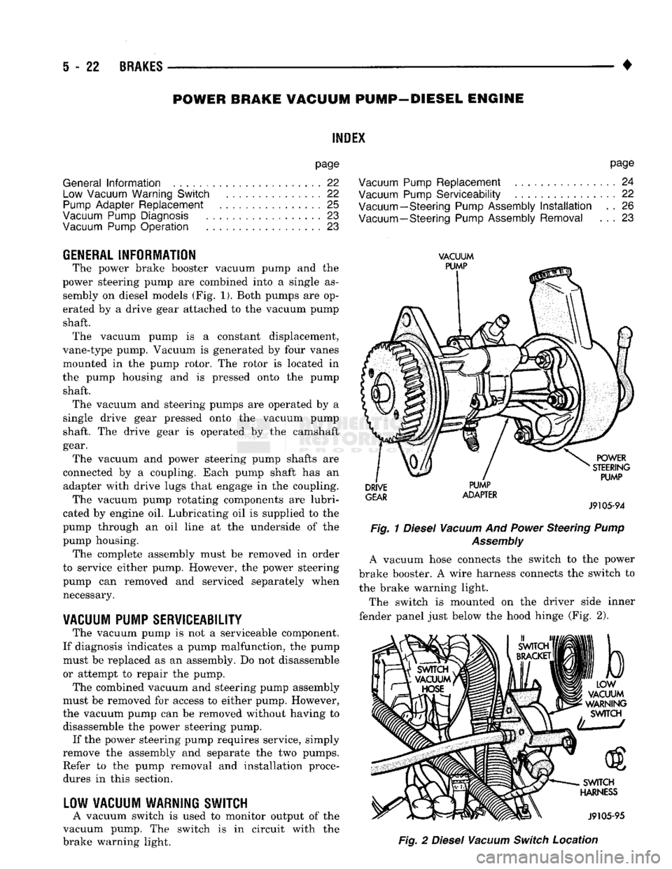
The power brake booster vacuum pump
and the
power steering pump
are
combined into
a
single
as
sembly
on
diesel models
(Fig. 1).
Both pumps
are op
erated
by a
drive gear attached
to the
vacuum pump shaft. The vacuum pump
is a
constant displacement,
vane-type pump. Vacuum
is
generated
by
four vanes
mounted
in the
pump rotor.
The
rotor
is
located
in
the pump housing
and is
pressed onto
the
pump shaft. The vacuum
and
steering pumps
are
operated
by a
single drive gear pressed onto
the
vacuum pump
shaft.
The
drive gear
is
operated
by the
camshaft
gear. The vacuum
and
power steering pump shafts
are
connected
by a
coupling. Each pump shaft
has an
adapter with drive lugs that engage
in the
coupling. The vacuum pump rotating components
are
lubri
cated
by
engine
oil.
Lubricating
oil is
supplied
to the
pump through
an oil
line
at the
underside
of the
pump housing. The complete assembly must
be
removed
in
order
to service either pump. However,
the
power steering
pump
can
removed
and
serviced separately when necessary.
VACUUM
PUMP
SERVICEABILITY
The vacuum pump
is not a
serviceable component.
If diagnosis indicates
a
pump malfunction,
the
pump must
be
replaced
as an
assembly.
Do not
disassemble
or attempt
to
repair
the
pump.
The combined vacuum
and
steering pump assembly
must
be
removed
for
access
to
either pump. However,
the vacuum pump
can be
removed without having
to
disassemble
the
power steering pump. If
the
power steering pump requires service, simply
remove
the
assembly
and
separate
the two
pumps. Refer
to the
pump removal
and
installation procedures
in
this section.
LOW
VACUUM
WARNING
SWITCH
A vacuum switch
is
used
to
monitor output
of the
vacuum pump.
The
switch
is in
circuit with
the
brake warning light.
VACUUM
PUMP
DRIVE
GEAR
PUMP
ADAPTER
POWER
STEERING
PUMP
J9105-94
Fig.
1
Diesel
Vacuum
And
Power
Steering
Pump
Assembly
A vacuum hose connects
the
switch
to the
power
brake booster.
A
wire harness connects
the
switch
to
the brake warning light.
The switch
is
mounted
on the
driver side inner
fender panel just below
the
hood hinge
(Fig. 2),
b
LOW
VACUUM
WARNING
SWITCH
SWITCH
HARNESS
J9105-95
Fig.
2
Diesel
Vacuum
Switch
Location
Page 210 of 1502
•
BRAKES
5 - 23
VACUUM PUMP OPERATION
Vacuum pump output is transmitted to the power
brake booster through a supply hose. The hose is con nected to an outlet port on the pump housing and to
the check valve in the power brake booster.
Pump output ranges from a minimum of 8.5 to 25
inches vacuum. The pump rotor and vanes are rotated by the pump
drive gear. The drive gear is operated by the cam
shaft gear. Booster vacuum level is monitored by a warning
switch (Fig. 2). The switch consists of a vacuum
chamber that measures vacuum level and a sensor in
circuit with the brake warning light. The vacuum chamber is connected to the booster
check valve by a vacuum supply hose. A wire har
ness connects the switch sensor to the brake warning
light. If booster vacuum falls below 8.5 inches for 8-10 seconds or more, the switch sensor completes
the circuit to the warning light causing it to illumi
nate.
VACUUM PUMP DIAGNOSIS
Vacuum pump diagnosis involves checking pump
output with a vacuum gauge. The low vacuum warn
ing switch can also be checked with a vacuum gauge.
Refer to the diagnosis procedure in this section. A standard vacuum gauge can be used to check
pump output when necessary. Simply disconnect the
pump supply hose and connect a vacuum gauge to
the outlet port for testing purposes. Vacuum should
hold steady in a range of approximately 8.5 to 25 inches at various engine speeds.
DIAGNOSING LOW VACUUM OUTPUT CONDITION A low booster vacuum condition or a faulty low
vacuum warning switch will cause the brake warn ing light to illuminate. If the light does go on and in
dicates the existence of a low vacuum condition,
check the vacuum pump, booster and warning switch
as follows:
(1) Check vacuum pump oil feed line. Verify that
line connections are secure and not leaking. If leak age is noted and pump is noisy, replace pump.
(2) Disconnect supply hose to booster. Connect vac
uum gauge to this hose and run engine at various
throttle openings. Output should range from 8.5 to 25 inches vacuum. If vacuum is consistently below
8.5 inches, problem is with vacuum hoses or pump
component. If output is within specified limits, con
tinue testing.
(3) Check booster operation as described in diagno
sis section. Replace check valve, vacuum hoses, or
booster if necessary. However, if booster operation is correct but warning light is still on, continue testing. (4) Disconnect vacuum hose at warning switch.
Plug hose and connect hand vacuum pump to switch. (5) Start and run engine.
(6) Apply 8.5 to 9 inches of vacuum to warning
switch and observe warning light. If light goes out,
switch vacuum hose is either loose or leaking. If
light remains on, leave engine running and continue
testing.
(7) Apply 20-25 inches vacuum to switch and ob
serve warning light operation. If light now goes out,
switch is at fault and should be replaced. If light re
mains on, continue testing.
(8) Reconnect vacuum hoses and replace original
warning switch with known good switch. Run engine and observe warning light operation. If light is now
off, old switch is faulty. If light remains on, problem
is in wiring between switch and warning light.
VACUUM-STEERING PUMP
ASSEMBLY
REMOVAL
(1) Disconnect battery negative cable.
(2) Position drain pan under power steering pump.
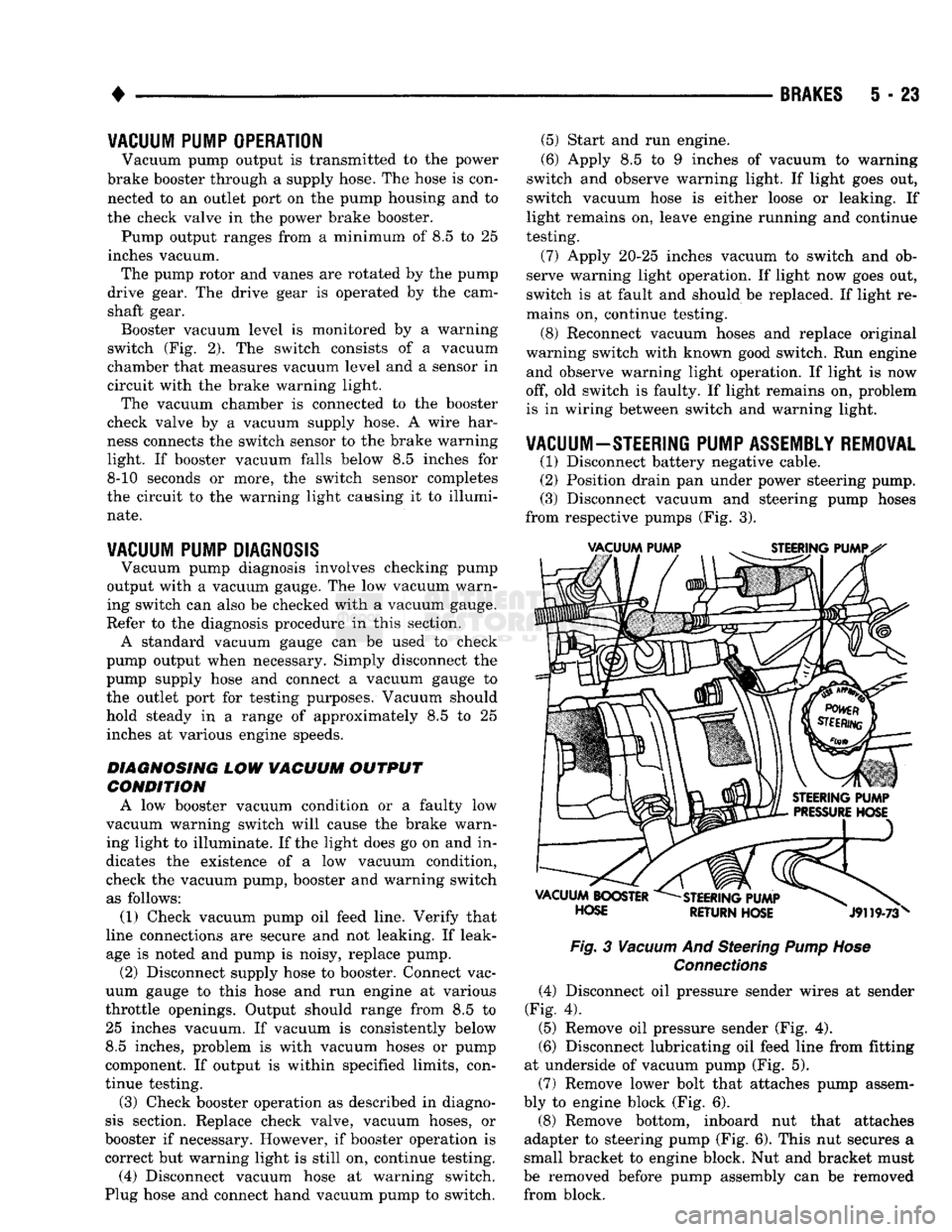
(3) Disconnect vacuum and steering pump hoses
from respective pumps (Fig. 3).
Fig.
3
Vacuum
And Steering
Pump Hose
Connections
(4) Disconnect oil pressure sender wires at sender
(Fig. 4).
(5) Remove oil pressure sender (Fig. 4).
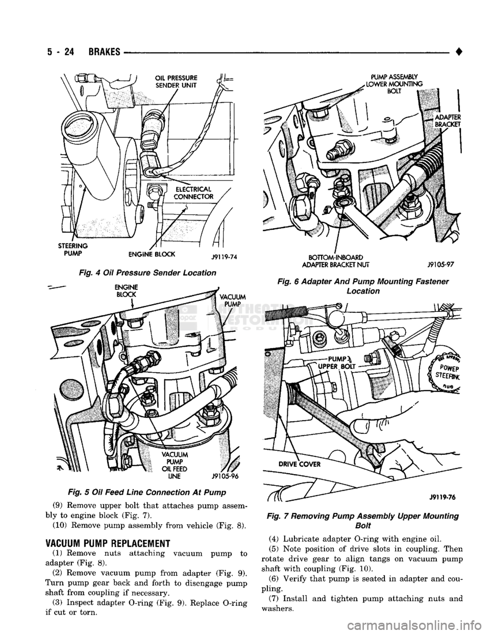
(6) Disconnect lubricating oil feed line from fitting
at underside of vacuum pump (Fig. 5).
(7) Remove lower bolt that attaches pump assem
bly to engine block (Fig. 6).
(8) Remove bottom, inboard nut that attaches
adapter to steering pump (Fig. 6). This nut secures a
small bracket to engine block. Nut and bracket must
be removed before pump assembly can be removed from block.
Page 211 of 1502
S
- 24
BRAKES
•
LINE
J9105-96
Fig. 5 Oil Feed Line Connection At Pump (9) Remove upper bolt that attaches pump assem
bly to engine block (Fig. 7).
(10) Remove pump assembly from vehicle (Fig. 8).
VACUUM PUMP REPLACEMENT
(1) Remove nuts attaching vacuum pump to
adapter (Fig. 8). (2) Remove vacuum pump from adapter (Fig. 9).
Turn pump gear back and forth to disengage pump shaft from coupling if necessary. (3) Inspect adapter O-ring (Fig. 9). Replace O-ring
if cut or torn.
PUMP ASSEMBLY
SOTTOM-INIOAiD
ADAPTER
BRACKET
NUT
J9105-97
Fig. 6 Adapter And
Pump
Mounting Fastener Location Fig. 7 Removing Pump Assembly Upper Mounting
Bolt
(4) Lubricate adapter O-ring with engine oil.
(5) Note position of drive slots in coupling. Then
rotate drive gear to align tangs on vacuum pump shaft with coupling (Fig. 10).
(6) Verify that pump is seated in adapter and cou
pling.
(7) Install and tighten pump attaching nuts and
washers.