1993 DODGE TRUCK engine oil
[x] Cancel search: engine oilPage 213 of 1502
5
- 26
BRAKES
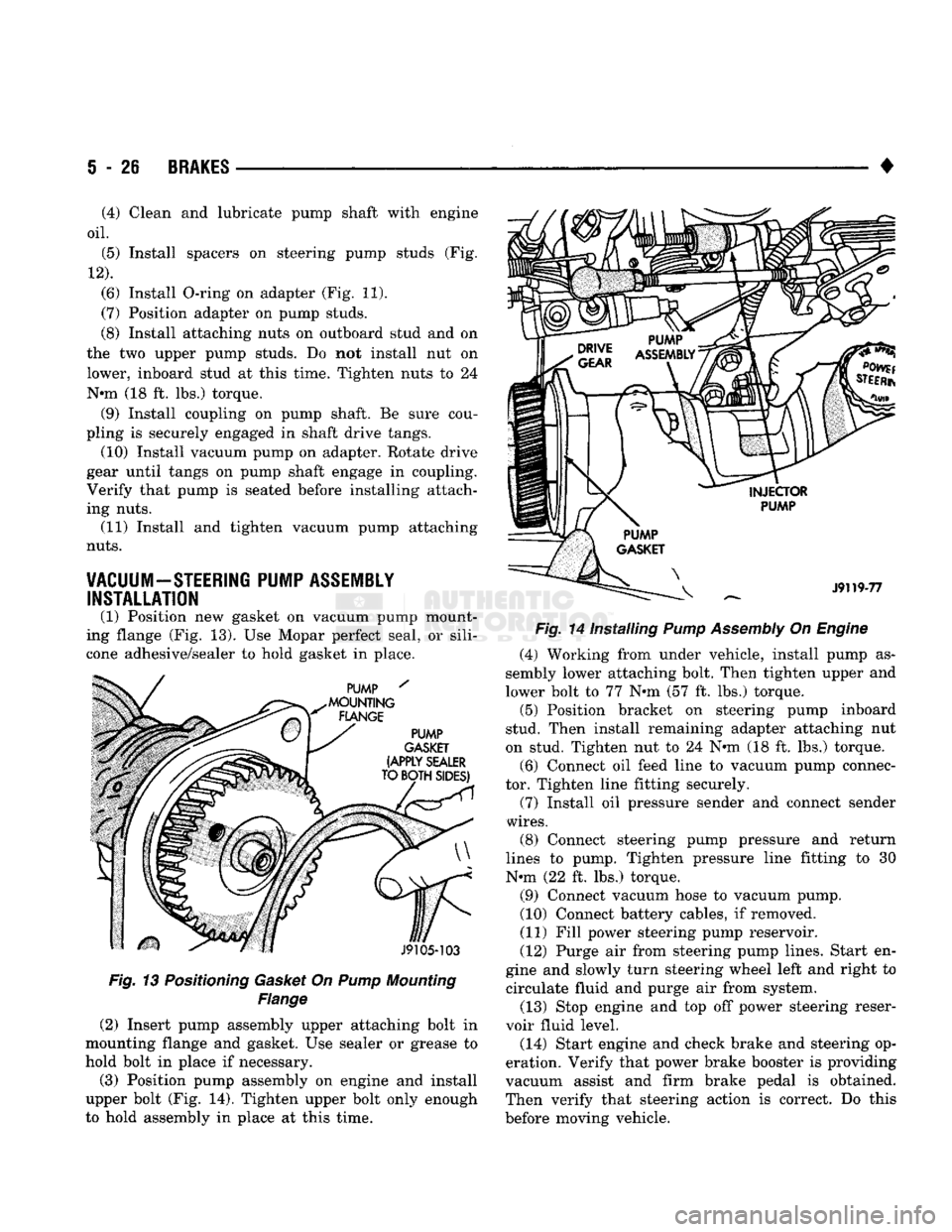
Fig. 13 Positioning Gasket On Pump Mounting
Flange
(2) Insert pump assembly upper attaching bolt in
mounting flange and gasket. Use sealer or grease to
hold bolt in place if necessary.
(3) Position pump assembly on engine and install
upper bolt (Fig. 14). Tighten upper bolt only enough
to hold assembly in place at this time. •
Fig. 14 Installing Pump Assembly On Engine (4) Working from under vehicle, install pump as
sembly lower attaching bolt. Then tighten upper and
lower bolt to 77 N»m (57 ft. lbs.) torque. (5) Position bracket on steering pump inboard
stud. Then install remaining adapter attaching nut
on stud. Tighten nut to 24 N«m (18 ft. lbs.) torque.
(6) Connect oil feed line to vacuum pump connec
tor. Tighten line fitting securely.
(7) Install oil pressure sender and connect sender
wires.
(8) Connect steering pump pressure and return
lines to pump. Tighten pressure line fitting to 30
N-m (22 ft. lbs.) torque.
(9) Connect vacuum hose to vacuum pump.
(10) Connect battery cables, if removed.
(11) Fill power steering pump reservoir.
(12) Purge air from steering pump lines. Start en
gine and slowly turn steering wheel left and right to circulate fluid and purge air from system.
(13) Stop engine and top off power steering reser
voir fluid level.
(14) Start engine and check brake and steering op
eration. Verify that power brake booster is providing
vacuum assist and firm brake pedal is obtained.
Then verify that steering action is correct. Do this
before moving vehicle.
(4) Clean and lubricate pump shaft with engine
oil.
(5) Install spacers on steering pump studs (Fig.
12).
(6) Install O-ring on adapter (Fig. 11).
(7) Position adapter on pump studs.
(8) Install attaching nuts on outboard stud and on
the two upper pump studs. Do not install nut on
lower, inboard stud at this time. Tighten nuts to 24
N-m (18 ft. lbs.) torque. (9) Install coupling on pump shaft. Be sure cou
pling is securely engaged in shaft drive tangs. (10) Install vacuum pump on adapter. Rotate drive
gear until tangs on pump shaft engage in coupling.
Verify that pump is seated before installing attach
ing nuts. (11) Install and tighten vacuum pump attaching
nuts.
VACUUM-STEERING PUMP ASSEMBLY INSTALLATION
(1) Position new gasket on vacuum pump mount
ing flange (Fig. 13). Use Mopar perfect seal, or sili
cone adhesive/sealer to hold gasket in place.
Page 259 of 1502
6 - 6
CLUTCH
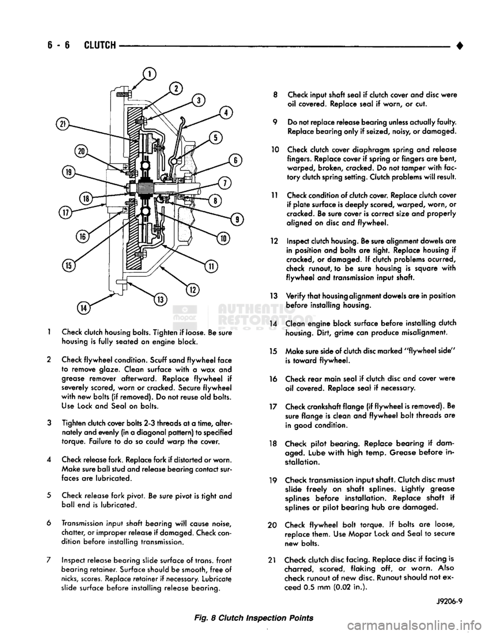
1
Check
clutch
housing bolts.
Tighten
if loose. Be sure
housing
is
fully
seated on engine block.
2 Check
flywheel
condition.
Scuff sand
flywheel
face
to remove glaze. Clean surface
with
a wax and
grease
remover afterward. Replace
flywheel
if
severely scored, worn or cracked. Secure
flywheel
with
new bolts (if removed). Do not reuse old bolts.
Use
Lock and Seal on bolts.
3
Tighten clutch cover bolts 2-3 threads at a
time,
alter
nately and evenly (in a diagonal
pattern)
to specified
torque. Failure to do so could warp the cover.
4 Check release fork. Replace fork if distorted or worn. Make sure ball stud and release bearing contact sur
faces
are lubricated.
5
Check release fork pivot. Be sure pivot is tight and ball end is lubricated.
6 Transmission input
shaft
bearing
will
cause noise,
chatter,
or improper release if
damaged.
Check
con
dition before installing transmission.
7 Inspect release bearing slide surface of trans,
front
bearing
retainer.
Surface should be smooth,
free
of
nicks,
scores.
Replace
retainer
if
necessary.
Lubricate slide surface before installing release bearing. 8 Check input shaft seal if clutch cover and
disc
were
oil covered. Replace seal if worn, or cut.
9 Do not replace release bearing
unless
actually
faulty.
Replace bearing only if seized, noisy, or damaged.
10 Check clutch cover diaphragm spring and release
fingers.
Replace cover if spring or fingers are bent, warped, broken, cracked. Do not tamper
with
fac
tory
clutch spring setting. Clutch problems
will
result.
11 Check condition of clutch cover. Replace clutch cover if
plate
surface is deeply scored, warped, worn, or
cracked. Be sure cover is correct size and properly
aligned on
disc
and flywheel.
12 Inspect clutch
housing.
Be sure alignment dowels are in position and bolts are tight. Replace housing if
cracked, or damaged. If clutch problems ocurred,
check runout, to be sure housing is square
with
flywheel
and transmission input shaft.
13
Verify
that
housing
alignment dowels are in position before installing
housing.
14 Clean engine block surface before installing clutch
housing.
Dirt, grime can produce misalignment.
15 Make sure side of clutch
disc
marked
"flywheel
side"
is
toward flywheel.
16 Check
rear
main seal if clutch
disc
and cover
were
oil covered. Replace seal if necessary.
17 Check crankshaft flange (if
flywheel
is removed). Be sure flange is clean and
flywheel
bolt threads are
in
good
condition.
18 Check pilot bearing. Replace bearing if dam
aged.
Lube
with
high temp. Grease before in
stallation.
19 Check transmission input shaft. Clutch
disc
must slide
freely
on shaft splines. Lightly grease
splines
before installation. Replace shaft if
splines
or pilot bearing hub are damaged.
20 Check
flywheel
bolt torque. If bolts are loose, replace them. Use Mopar Lock and Seal to secure
new bolts.
21 Check clutch
disc
facing. Replace
disc
if facing is charred, scored, flaking off, or worn.
Also
check runout of new
disc.
Runout should not ex
ceed 0.5 mm (0.02 in.).
J9206-9
Fig. 8 Clutch Inspection Points
Page 262 of 1502
•
CLUTCH
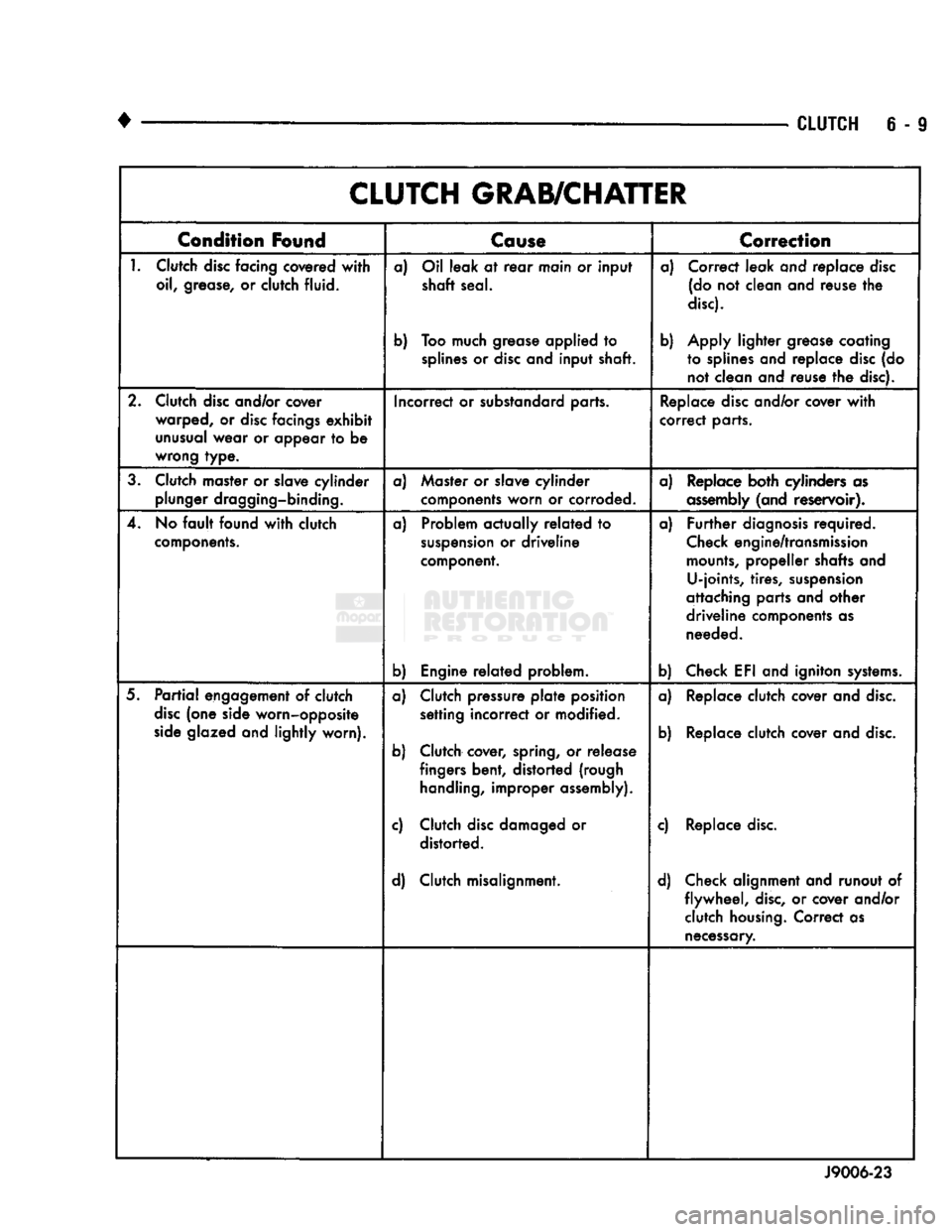
6 - 9 CLUTCH GRAB/CHATTER
Condition
Found
Cause
T
Correction
1.
Clutch
disc
facing covered
with
oil, grease, or clutch fluid. a) Oil leak at
rear
main or input
shaft seal.
b) Too much grease applied to
splines
or
disc
and input shaft. a) Correct leak and replace
disc
(do not clean and reuse the
disc).
b) Apply lighter grease coating to splines and replace
disc
(do not clean and reuse the disc).
2. Clutch
disc
and/or cover warped, or
disc
facings
exhibit
unusual
wear or appear to be
wrong type. Incorrect or substandard parts.
Replace
disc
and/or cover
with
correct parts.
3. Clutch master or slave cylinder plunger dragging-binding. a) Master or slave cylinder
components worn or corroded. a) Replace both cylinders as
assembly
(and reservoir).
4. No
fault
found
with
clutch
components.
a) Problem actually
related
to
suspension
or driveline
component.
b) Engine
related
problem. a)
Further
diagnosis
required.
Check
engine/transmission
mounts,
propeller shafts and U-joints, tires,
suspension
attaching parts and other
driveline components as needed.
b) Check EFI and igniton
systems.
5.
Partial
engagement of clutch
disc
(one side worn-opposite
side
glazed and lightly worn). a) Clutch pressure
plate
position
setting incorrect or modified.
b) Clutch cover, spring, or release fingers bent, distorted (rough
handling,
improper assembly).
c) Clutch
disc
damaged or distorted.
d) Clutch misalignment. a) Replace clutch cover and
disc.
b) Replace clutch cover and
disc.
c) Replace
disc.
d) Check alignment and runout of flywheel,
disc,
or cover and/or clutch
housing.
Correct as
necessary.
J9006-23
Page 273 of 1502
7 - 2
COOLING
SYSTEM
•
NOTE: HEATER
COOLANT FLOW
CIRCUIT
IS
ALWAYS
OPEN
EXCEPT
WHEN
IN MAX. A/C
OR
OFF
MODES
HEATER
INTAKE MANIFOLD
COOLANT FLOW "METERED" FROM REAR
TO
FRONT
AND
BELOW EXHAUST HEAT
CROSSOVER
SHUT
OFF
VALVE
A/C
ONLY COOLANT FLOW
-
PUMP
TO
CYLINDER
BLOCK,
UP
THROUGH
CYLINDER
HEADS
TO
INTAKE MANIFOLD WATER BOX
TO
RADIATOR
—
TO PUMP
•BYPASS
THERMOSTAT CLOSED-HIGH FLOW
THERMOSTAT OPEN
-
LOW FLOW
CYLINDER
HEAD
RR07B52
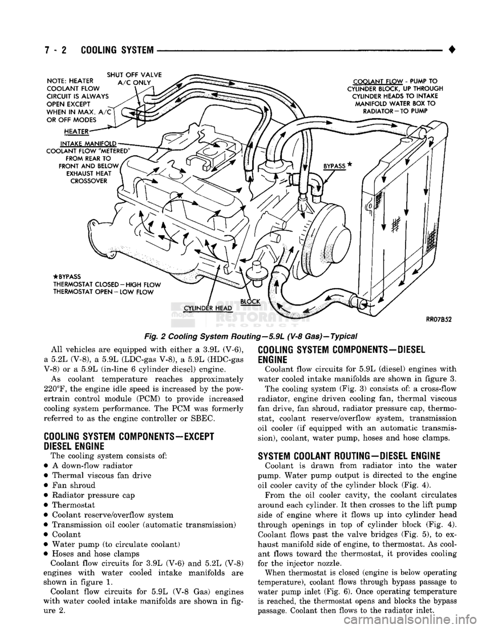
Fig.
2
Cooling
System
Routing—5.9L (V-8 Gas)—Typical All vehicles are equipped with either a 3.9L (V-6),
a 5.2L (V-8), a 5.9L (LDC-gas V-8), a 5.9L (HDC-gas
V-8) or a 5.9L (in-line 6 cylinder diesel) engine.
As coolant temperature reaches approximately
220°F,
the engine idle speed is increased by the pow-
ertrain control module (PCM) to provide increased
cooling system performance. The PCM was formerly
referred to as the engine controller or SBEC.
COOLING
SYSTEM
COMPONENTS—EXCEPT
DIESEL
ENGINE
The cooling system consists of:
• A down-flow radiator
• Thermal viscous fan drive
• Fan shroud
• Radiator pressure cap
• Thermostat
• Coolant reserve/overflow system
• Transmission oil cooler (automatic transmission)
• Coolant
• Water pump (to circulate coolant)
• Hoses and hose clamps Coolant flow circuits for 3.9L (V-6) and 5.2L (V-8)
engines with water cooled intake manifolds are
shown in figure 1. Coolant flow circuits for 5.9L (V-8 Gas) engines
with water cooled intake manifolds are shown in fig ure 2.
COOLING
SYSTEM
COMPONENTS-DIESEL
ENGINE
Coolant flow circuits for 5.9L (diesel) engines with
water cooled intake manifolds are shown in figure 3. The cooling system (Fig. 3) consists of: a cross-flow
radiator, engine driven cooling fan, thermal viscous
fan drive, fan shroud, radiator pressure cap, thermo stat, coolant reserve/overflow system, transmission
oil cooler (if equipped with an automatic transmis
sion),
coolant, water pump, hoses and hose clamps.
SYSTEM
COOLANT ROUTING-DIESEL ENGINE
Coolant is drawn from radiator into the water
pump. Water pump output is directed to the engine oil cooler cavity of the cylinder block (Fig. 4). From the oil cooler cavity, the coolant circulates
around each cylinder. It then crosses to the lift pump
side of engine where it flows up into cylinder head
through openings in top of cylinder block (Fig. 4). Coolant flows past the valve bridges (Fig. 5), to ex
haust manifold side of engine, to thermostat. As cool ant flows toward the thermostat, it provides cooling
for the injector nozzle.
When thermostat is closed (engine is below operating
temperature), coolant flows through bypass passage to
water pump inlet (Fig. 6). Once operating temperature is reached, the thermostat opens and blocks the bypass
passage. Coolant then flows to the radiator inlet.
Page 276 of 1502
•
COOLING
SYSTEM
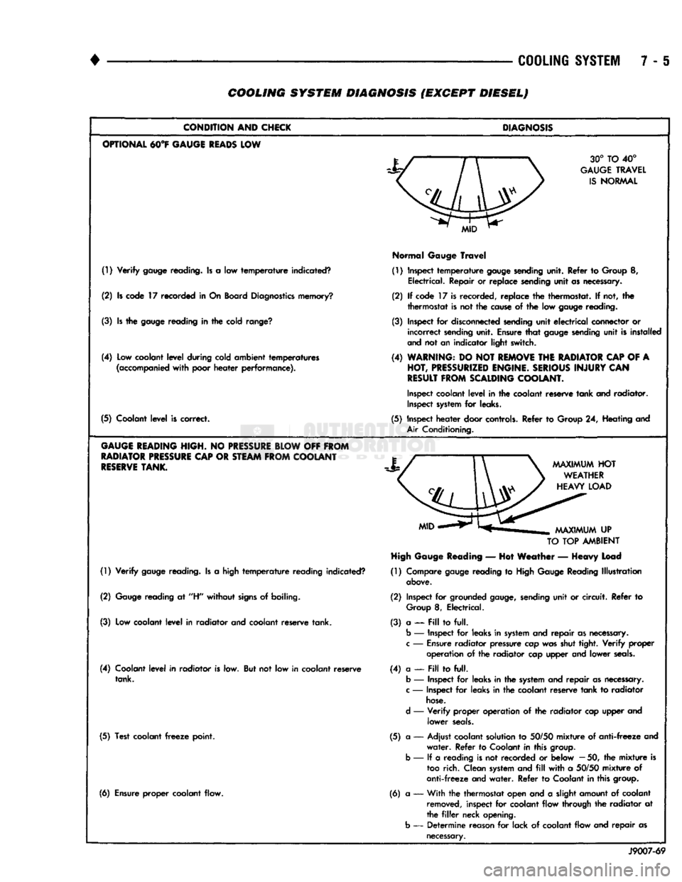
7 - 6 COOLING SYSTEM DIAGNOSIS (EXCEPT DIESEL)
CONDITION
AND
CHICK
OPTIONAL
M°¥
GAUGE
READS
LOW
(!) Verify
gauge
reading. Is a low temperature indicated?
(2) Is code 17 recorded in On Board
Diagnostics
memory?
(3) Is the
gauge
reading in the cold
range?
(4) Low coolant level during cold ambient temperatures
(accompanied
with poor heater performance).
(5) Coolant level is correct.
GAUGE
HEADING
HIGH.
NO
PRESSURE
BLOW
OFF
FROM
RADIATOR
PRESSURE
CAP
OR
STEAM
FROM
COOLANT
RESERVE
TANK.
(1) Verify
gauge
reading. Is a high temperature reading indicated?
(2)
Gauge
reading at
"H"
without
signs
of boiling.
(3) Low coolant level in radiator and coolant reserve tank.
(4) Coolant level in radiator is low. But not low in coolant reserve tank.
(5) Test coolant
freeze
point.
(6) Ensure proper coolant flow.
DIAGNOSIS
30° TO 40°
GAUGE
TRAVEL
IS
NORMAL
Normal
Gauge
Travel
(1) Inspect temperature
gauge
sending
unit. Refer to Group 8, Electrical. Repair or replace sending unit as necessary.
(2) If code 17 is recorded, replace the thermostat. If not, the thermostat is not the
cause
of the low
gauge
reading.
(3) Inspect for
disconnected
sending
unit electrical connector or incorrect
sending
unit. Ensure that
gauge
sending
unit is installed
and
not an indicator light switch.
(4)
WARNING:
DO NOT
REMOVE
THE
RADIATOR
CAP
OF A
HOT,
PRESSURIZED
ENGINE.
SERIOUS
INJURY
CAN
RESULT
FROM
SCALDING
COOLANT.
Inspect
coolant level in the coolant reserve tank and radiator.
Inspect
system
for leaks.
(5) Inspect heater door
controls.
Refer to Group 24, Heating and
Air
Conditioning.
TO
TOP
AMBIENT
High
Gauge
Reading
— Hot Weather — Heavy Load
(1) Compare
gauge
reading to
High
Gauge
Reading Illustration
above.
(2) Inspect for grounded
gauge,
sending
unit or circuit. Refer to
Group
8, Electrical.
(3) a — Pill to full.
b
— Inspect for leaks in
system
and repair as
necessary,
c
—
Ensure
radiator pressure cap was shut tight. Verify
proper
operation of the radiator cap upper and lower
seals.
(4) a —
Fill
to full,
b
— Inspect for leaks in the
system
and repair as
necessary,
c
— Inspect for leaks in the coolant reserve tank to radiator
hose.
d
— Verify proper operation of the radiator cap upper and lower
seals.
(5) a — Adjust coolant solution to
50/50
mixture of anti-freeze and water. Refer to Coolant in this
group,
b
— If a reading is not recorded or below
—
50, the mixture is
too
rich. Clean
system
and
fill
with a
50/50
mixture of
anti-freeze and water. Refer to Coolant in this
group.
(6) a •— With the thermostat open and a slight amount of coolant
removed,
inspect for coolant flow through the radiator at
the
filler
neck opening,
b
— Determine reason for lack of coolant flow and repair as
necessary.
J9007-69
Page 278 of 1502
•
COOLING
SYSTEM
7 - 7 COOLING SYSTEM DIAGNOSIS (EXCEPT DIESELJ-GONTINUED
CONDITION
AND
CHECKS
DIAGNOSIS
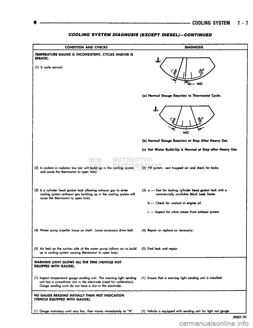
TEMPERATURE
GAUGE
IS
INCONSISTENT,
CYCLES
AND/OR
IS
ERRATIC.
(1) Is cycle normal.
MID
(a)
Normal Gauge Reaction to Thermostat Cycle.
MID
(b) Normal Gauge Reaction at Stop After Heavy Use.
(c) Hot Water Build-Up is Normal at
Stop
after
Heavy Use.
(2)
Is
coolant in radiator low (air
will
build up in the cooling
system
(2)
Fill
system,
vent trapped air and check for leaks,
and
cause
the thermostat to open
late).
(3)
Is
a cylinder head gasket leak allowing exhaust
gas
to
enter
(3) a — Test for leaking cylinder head
gasket
leak
with
a
cooling
system
(exhaust
gas
building up in the cooling
system
will
commercially available Block Leak Tester,
cause
the thermostat to open
late).
b
— Check for coolant in engine oil.
c
— Inspect for
white
steam from exhaust
system.
(4)
Water pump impeller loose on shaft.
Loose
accessory
drive belt. (4) Repair or replace as necessary.
(5)
Air leak
on
the
suction
side of the
water
pump (allows air to build (5) Find leak and repair,
up
in cooling
system
causing
thermostat to open
late).
WARNING
LIGHT
GLOWS
ALL
THE
TIME
(VEHICLE
NOT
EQUIPPED
WITH
GAUGE).
(1) Inspect
temperature
gauge
sending
unit. The warning light
sending
(1)
Ensure
that
a warning light
sending
unit
is
installed, unit
has
a screwdriver slot in the electrode (used for calibration).
Gauge
sending
units do not have a slot in the electrode.
NO
GAUGE
READING
INITIALLY
THEN
HOT
INDICATION
(VEHICLE
EQUIPPED
WITH
GAUGE).
(1)
Gauge
stationary
until
very hot, then
moves
immediately to "H"
(1)
Vehicle
is
equipped
with
sending
unit for light not
gauge.
J9007-70
Page 281 of 1502
7-10 COOLING SYSTEM
•
DIESEL
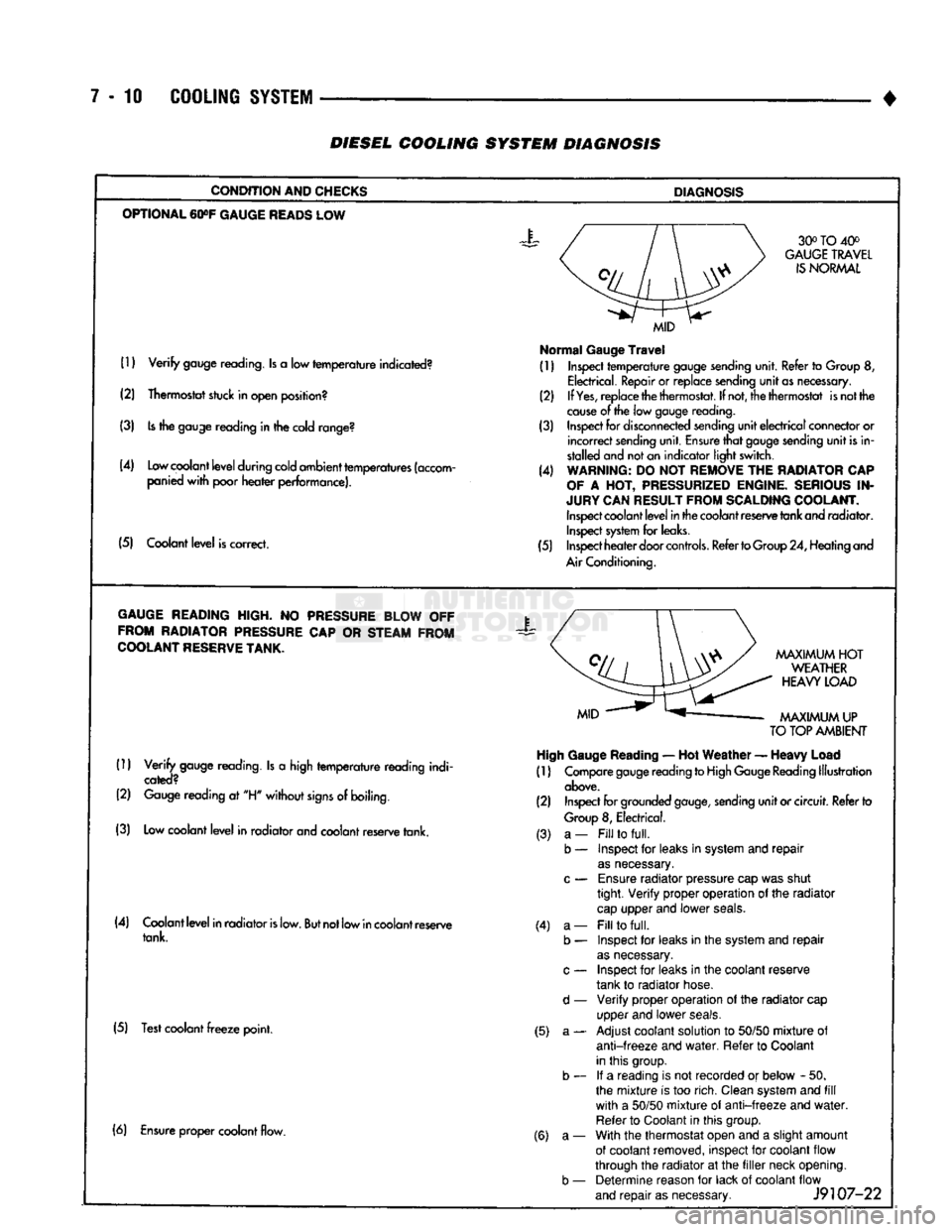
COOLING SYSTEM
DIAGNOSIS
CONDITION AND CHECKS
DIAGNOSIS
OPTIONAL
60»F
GAUGE
READS
LOW 30° TO 40°
GAUGE
TRAVEL
IS
NORMAL
(1)
Verify
gauge reading. Is a low
temperature
indicated?
(2) Thermostat stuck in open position?
(3) Is the gauge reading in the cold range?
(4) Low coolant
level
during cold ambient temperatures (accom panied
with
poor
heater
performance).
(5) Coolant
level
is correct.
MID
Normal
Gauge
Travel
(1) Inspect
temperature
gauge sending unit. Refer to Group 8,
Electrical. Repair or replace sending
unit
as necessary.
(2) If
Yes,
replace the thermostat. If not, the thermostat is not the
cause
of the low gauge
reading.
(3) Inspect for disconnected sending
unit
electrical
connector or
incorrect
sending unit. Ensure
that
gauge sending
unit
is in
stalled and not an indicator light switch.
(4) WARNING: DO NOT REMOVE THE RADIATOR CAP
OF
A HOT, PRESSURIZED ENGINE. SERIOUS IN
JURY CAN RESULT FROM SCALDING COOLANT. Inspect coolant
level
in the coolant reserve tank and radiator. Inspect system for leaks.
(5) Inspect
heater
door
controls.
Refer to Group 24, Heating and
Air Conditioning.
GAUGE
READING HIGH. NO PRESSURE BLOW OFF FROM RADIATOR PRESSURE CAP OR STEAM FROM
COOLANT
RESERVE
TANK.
X
(1)
Verify
gauge reading. Is a high
temperature
reading indi
cated?
(2) Gauge reading at "H"
without
signs
of boiling.
(3) Low coolant
level
in radiator and coolant reserve tank.
MAXIMUM
HOT
WEATHER
HEAVY
LOAD
MAXIMUM
UP
TO
TOP AMBIENT High Gauge
Reading
— Hot
Weather
—
Heavy
Load
(1) Compare gauge reading to High Gauge Reading Illustration
above.
(2) Inspect for grounded
gauge,
sending
unit
or circuit. Refer to
Group
8, Electrical.
(4) Coolant
level
in radiator
is
low.
But
not low in coolant reserve tank.
(5) Test coolant
freeze
point. (3) a-
b — (4) a-
b —
d —
(5) a- (6) Ensure proper coolant flow.
(6) a-
b —
Fill
to
full.
Inspect for leaks in system and
repair
as
necessary.
Ensure
radiator pressure cap was shut
tight.
Verify
proper operation of the radiator
cap
upper and lower
seals.
Fill
to
full.
Inspect for leaks in the system and
repair
as
necessary.
Inspect for leaks in the coolant reserve
tank to radiator hose.
Verify
proper operation of the radiator cap
upper and lower
seals.
Adjust coolant solution to
50/50
mixture
of
anti-freeze
and
water.
Refer to Coolant
in this group. If a reading is not recorded or below - 50.
the
mixture
is too rich. Clean system and
fill
with
a
50/50
mixture
of
anti-freeze
and
water.
Refer to Coolant in this group.
With the thermostat open and a slight amount
of coolant removed, inspect for coolant flow
through the radiator at the
filler
neck opening. Determine reason for lack of coolant flow
and
repair
as necessary.
J9107-22
Page 286 of 1502
•
COOLING SYSTEM
7 - 15
SERVICE
PROCEDURES
INDEX
page
Coolant
26
Coolant Reserve/Overflow System
30
Cooling System Cleaning/Reverse Flushing
28
Cooling System Fan—Diesel Engine
. 37
Cooling System
Fan—Gas
Engines
36
Cooling System
Hoses
34
Draining Cooling System
27
Pressure
Testing
Radiator
Caps
............. 32
Radiator Pressure
Cap 31
Radiators
32
Refilling
the
Cooling System
28
WATER PUMPS—EXCEPT DIESEL
A centrifugal water pump circulates coolant
through the water jackets, passages, intake manifold,
radiator core, cooling system hoses and heater core.
The pump is driven from the engine crankshaft by a drive belt. The water pump impeller is pressed onto the rear
of a shaft that rotates in a bearing pressed into the
water pump body. The body has a small hole for ven
tilation. The water pump seals are lubricated by an
tifreeze in the coolant mixture. Additional lubrication is not necessary. A quick test to determine if pump is working is to
check if heater warms properly. A defective water
pump will not be able to circulate heated coolant
through the long heater hose to the heater core. The water pump on all models can be removed
without discharging the air conditioning system (if equipped).
REMOVAL The water pump on all gas powered engines is
bolted directly to the engine timing chain case/cover.
A gasket is used as a seal between the water pump
and timing chain case/cover.
If water pump is replaced because of bearing/shaft
damage or leaking shaft seal, the mechanical cooling
fan assembly should also be inspected. Inspect for fa tigue cracks, loose blades or loose rivets that could
have resulted from excessive vibration. Replace fan if any of these conditions are found. Also check condi
tion of the thermal viscous fan drive. Refer to Vis
cous Fan Drive in this group. (1) Disconnect negative battery cable from battery.
(2) Drain cooling system. Refer to Draining Cool
ing System in this group. Do not waste reusable coolant. If solution is clean,
drain coolant into a clean container for reuse.
(3)
Disconnect throttle cable from clip at top of fan
shroud.
page
Testing
Cooling System
for
Leaks
. 29
Thermostat
22
Transmission
Oil
Cooler—Diesel
35
Transmission
Oil
Cooler—Except Diesel
35
Transmission Oil-To-Air Cooler
36
Viscous
Fan
Drive
38
Water
Pump
Bypass
Hose—All
Gas
Powered
Engines
.............................. 19
Water
Pumps—5.9L Diesel
18
Water
Pumps—Except Diesel
15
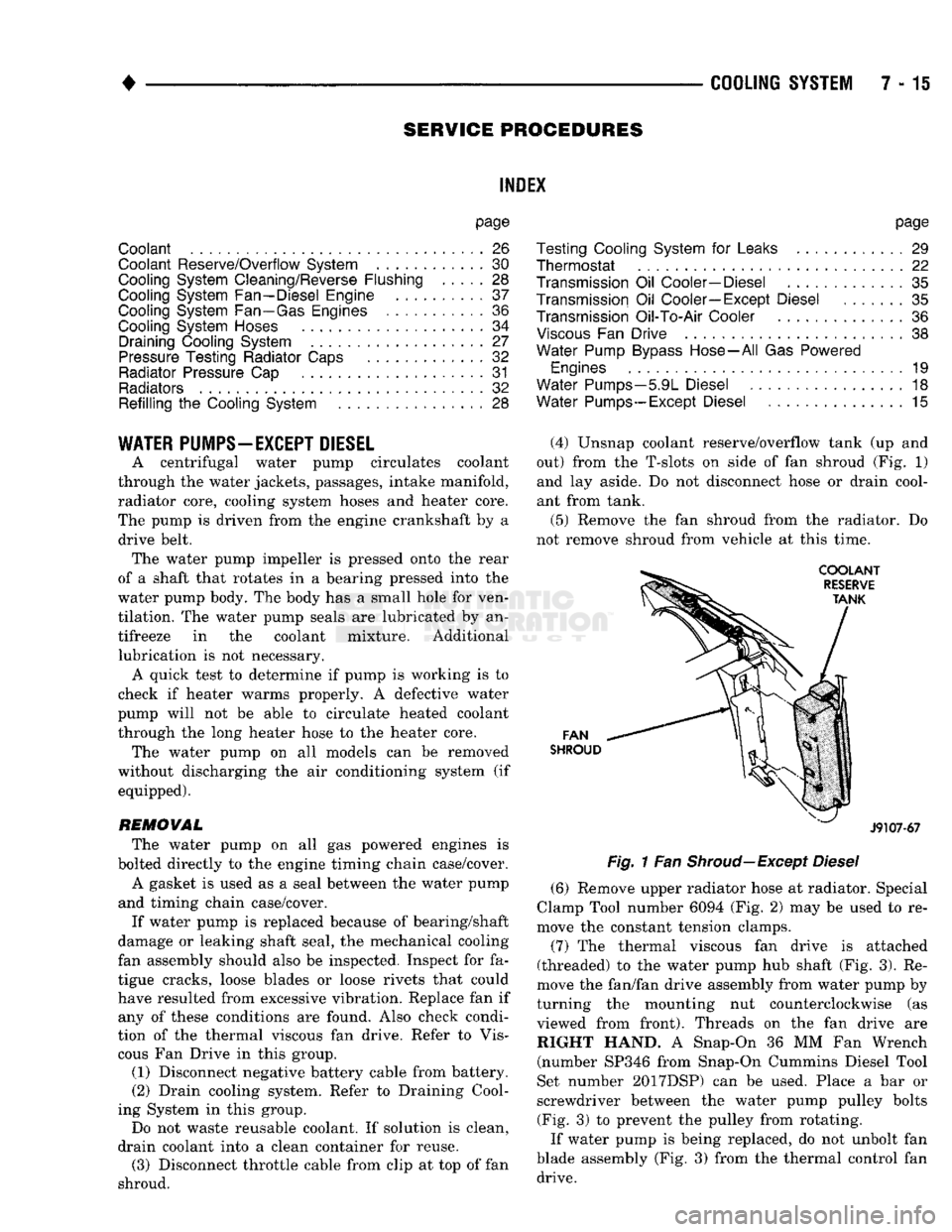
(4) Unsnap coolant reserve/overflow tank (up and
out) from the T-slots on side of fan shroud (Fig. 1) and lay aside. Do not disconnect hose or drain cool
ant from tank.
(5) Remove the fan shroud from the radiator. Do
not remove shroud from vehicle at this time.
FAN
SHROUD
J9107-67
Fig.
1 Fan
Shroud—Except
Diesel
(6) Remove upper radiator hose at radiator. Special
Clamp Tool number 6094 (Fig. 2) may be used to re
move the constant tension clamps.
(7) The thermal viscous fan drive is attached
(threaded) to the water pump hub shaft (Fig. 3). Re
move the fan/fan drive assembly from water pump by
turning the mounting nut counterclockwise (as viewed from front). Threads on the fan drive are RIGHT HAND. A Snap-On 36 MM Fan Wrench (number SP346 from Snap-On Cummins Diesel Tool
Set number 2017DSP) can be used. Place a bar or
screwdriver between the water pump pulley bolts (Fig. 3) to prevent the pulley from rotating.
If water pump is being replaced, do not unbolt fan
blade assembly (Fig. 3) from the thermal control fan drive.