1993 DODGE TRUCK coolant level
[x] Cancel search: coolant levelPage 753 of 1502
9 - 150 5.9L
(DIESEL) ENGINE
•
INSTALLATION
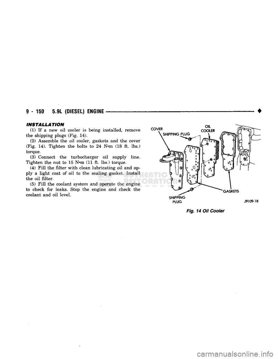
(1) If a new oil cooler is being installed, remove
the shipping plugs (Fig. 14). (2) Assemble the oil cooler, gaskets and the cover
(Fig. 14). Tighten the bolts to 24 N-m (18 ft. lbs.)
torque. (3) Connect the turbocharger oil supply line.
Tighten the nut to 15 N-m (11 ft. lbs.) torque. (4) Fill the filter with clean lubricating oil and ap
ply a light coat of oil to the sealing gasket. Install the oil filter. (5) Fill the coolant system and operate the engine
to check for leaks. Stop the engine and check the
coolant and oil level.
SHIPPING
PLUG
J9109-18
Fig.
14 Oil
Cooler
Page 850 of 1502
•
FUEL SYSTEM
14-31 through different system components. These compo
nents are referred to as Powertrain Control Module
(PCM) Outputs. The sensors and switches that pro
vide inputs to the PCM are considered Powertrain Control Module (PCM) Inputs.
The PCM adjusts ignition timing based upon in
puts it receives from sensors that react to: engine rpm, manifold absolute pressure, engine coolant tem
perature, throttle position, transmission gear selec
tion (automatic transmission), vehicle speed and the
brake switch.
The PCM adjusts idle speed based on inputs it re
ceives from sensors that react to: throttle position,
vehicle speed, transmission gear selection, engine coolant temperature and from inputs it receives from
the air conditioning clutch switch and brake switch.
Based on inputs that it receives, the PCM adjusts
ignition coil dwell. The PCM also adjusts the gener
ator charge rate through control of the generator
field and provides speed control operation.
Powertrain Control Module (PCM) Inputs:
• Generator output • A/C request (if equipped with factory A/C)
• A/C select (if equipped with factory A/C)
• Auto shut down (ASD) sense
• Charge air temperature sensor
• Battery voltage
• Brake switch
• Engine coolant temperature sensor
• Crankshaft position sensor • Ignition circuit sense (ignition switch in run posi
tion)
• Manifold absolute pressure (MAP) sensor
• Overdrive/override switch
• Oxygen sensor(s)
• Park/neutral switch (auto, trans, only)
• SCI receive (DRB II connection) • Speed control resume switch
• Speed control set switch • Speed control on/off switch
• Camshaft position sensor signal
• Throttle position sensor
• Vehicle speed sensor
• Sensor return
• Power ground
• Signal ground Powertrain Control Module (PCM) Outputs:
• A/C clutch relay
• Idle air control (IAC) motor
• Auto shut down (ASD) relay
• Generator field
• Malfunction indicator lamp
• Service reminder indicator lamp
• EGR valve control solenoid • Fuel injectors
• Fuel pump relay
• Ignition coil • EVAP canister purge solenoid
• SCI transmit (DRB II connection)
• Shift indicator lamp (manual transmission only)
• Speed control vacuum solenoid
• Speed control vent solenoid
• Tachometer (on instrument panel, if equipped) The powertrain control module (PCM) contains a
voltage convertor. This converts battery voltage to a
regulated 8.0 volts. It is used to power the crankshaft
position sensor and camshaft position sensor. The
PCM also provides a five (5) volt supply for the man ifold absolute pressure (MAP) sensor and throttle po
sition sensor (TPS).
AIR
CONDITIONING
(A/C)
CONTROLS-PCM
INPUT
The A/C control system information applies to fac
tory installed air conditioning units. A/C SELECT SIGNAL: When the A/C switch is
in the ON position and the A/C low pressure switch
is closed, an input signal is sent to the powertrain
control module (PCM). The signal informs the PCM
that the A/C has been selected. The PCM adjusts idle speed to a pre-programmed rpm through the idle air
control (IAC) motor to compensate for increased en
gine load. A/C REQUEST SIGNAL: Once A/C has been se
lected, the powertrain control module (PCM) receives
the A/C request signal from the evaporator switch.
The input indicates that the evaporator temperature is in the proper range for A/C application. The PCM
uses this input to cycle the A/C compressor clutch (through the A/C relay). It will also determine the
correct engine idle speed through the idle air control (IAC) motor position. If the A/C low pressure switch opens (indicating a
low refrigerant level), the PCM will not receive an
A/C select signal. The PCM will then remove the ground from the A/C relay. This will deactivate the
A/C compressor clutch. If the evaporator switch opens, (indicating that
evaporator is not in proper temperature range), the
PCM will not receive the A/C request signal. The
PCM will then remove the ground from the A/C re lay, deactivating the A/C compressor clutch.
AUTOMATIC SHUT DOWN
(ASD)
SENSE-PCM INPUT
A 12 volt signal at this input indicates to the PCM
that the ASD has been activated. The ASD relay is located in the engine compartment (Fig. 2). It is used
to connect the oxygen sensor(s) heater element, igni
tion coil, generator field winding and fuel injectors to 12 volt + power supply. This input is used only to sense that the ASD relay
is energized. If the powertrain control module (PCM)
does not see 12 volts at this input when the ASD
should be activated, it will set a diagnostic trouble
code (DTC).
Page 852 of 1502
•
FUEL SYSTEM
14 - 33 Refer to Group 8D, Ignition System for more crank
shaft position sensor information. The engine will not operate if the PCM does not re
ceive a crankshaft position sensor input.
ENGINE
COOLANT TEMPERATURE SENSOR-PCM
INPUT
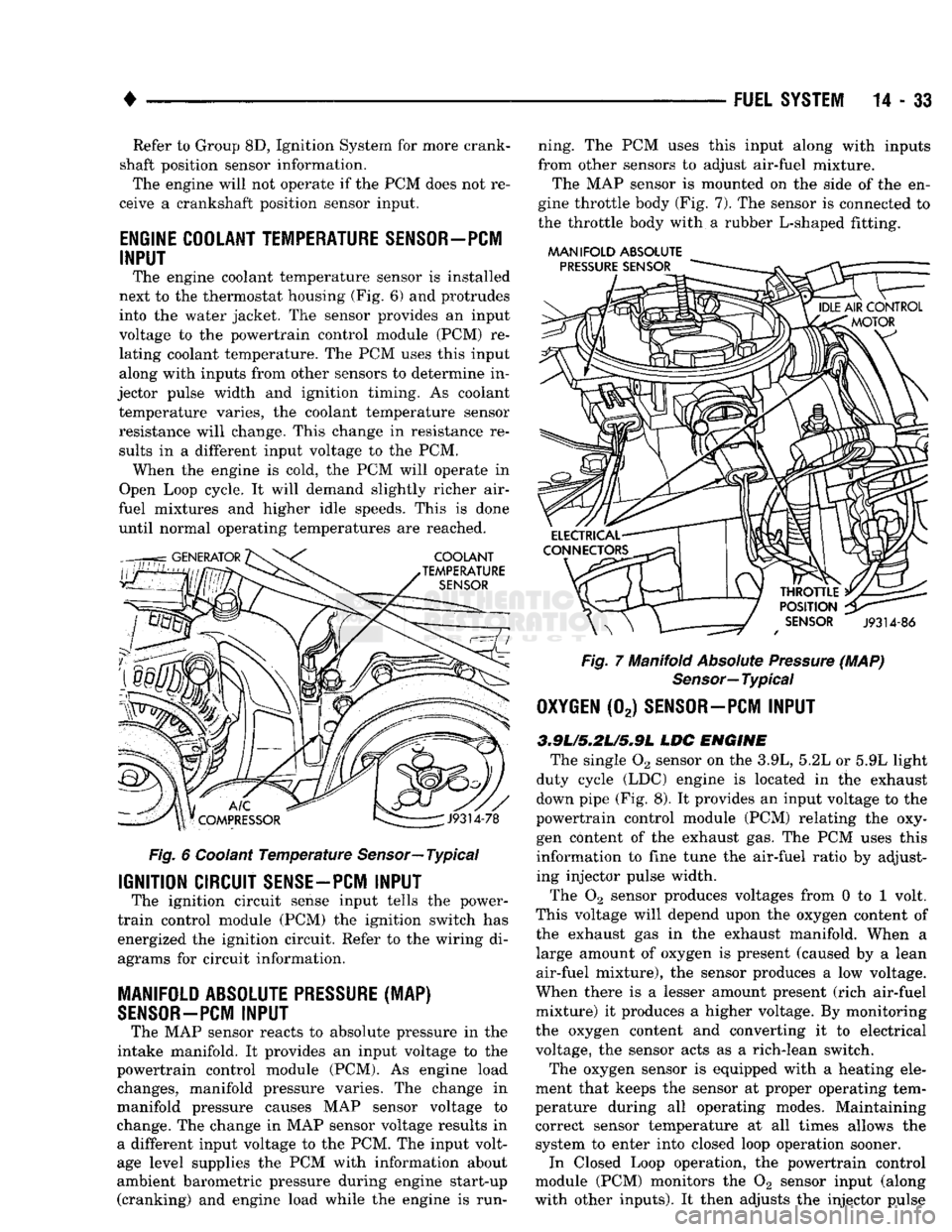
The engine coolant temperature sensor is installed
next to the thermostat housing (Fig. 6) and protrudes
into the water jacket. The sensor provides an input
voltage to the powertrain control module (PCM) re
lating coolant temperature. The PCM uses this input
along with inputs from other sensors to determine in
jector pulse width and ignition timing. As coolant temperature varies, the coolant temperature sensor
resistance will change. This change in resistance results in a different input voltage to the PCM. When the engine is cold, the PCM will operate in
Open Loop cycle. It will demand slightly richer air-
fuel mixtures and higher idle speeds. This is done until normal operating temperatures are reached.
Fig.
6 Coolant
Temperature
Sensor—
Typical
IGNITION CIRCUIT
SENSE-PCM
INPUT
The ignition circuit sense input tells the power-
train control module (PCM) the ignition switch has
energized the ignition circuit. Refer to the wiring di
agrams for circuit information.
MANIFOLD ABSOLUTE
PRESSURE
(MAP)
SENSOR-PCM
INPUT
The MAP sensor reacts to absolute pressure in the
intake manifold. It provides an input voltage to the
powertrain control module (PCM). As engine load changes, manifold pressure varies. The change in
manifold pressure causes MAP sensor voltage to
change. The change in MAP sensor voltage results in a different input voltage to the PCM. The input volt
age level supplies the PCM with information about
ambient barometric pressure during engine start-up (cranking) and engine load while the engine is run ning. The PCM uses this input along with inputs
from other sensors to adjust air-fuel mixture.
The MAP sensor is mounted on the side of the en
gine throttle body (Fig. 7). The sensor is connected to
the throttle body with a rubber L-shaped fitting.
MANIFOLD
ABSOLUTE
Fig.
7 Manifold
Absolute
Pressure
(MAP)
Sensor—
Typical
OXYGEN
(02)
SENSOR—PCM
INPUT
3.9L/5.2L/S»9L
LDC
ENGINE
The single 02 sensor on the 3.9L, 5.2L or 5.9L light
duty cycle (LDC) engine is located in the exhaust
down pipe (Fig. 8). It provides an input voltage to the
powertrain control module (PCM) relating the oxy
gen content of the exhaust gas. The PCM uses this
information to fine tune the air-fuel ratio by adjust ing injector pulse width.
The 02 sensor produces voltages from 0 to 1 volt.
This voltage will depend upon the oxygen content of
the exhaust gas in the exhaust manifold. When a large amount of oxygen is present (caused by a lean
air-fuel mixture), the sensor produces a low voltage.
When there is a lesser amount present (rich air-fuel
mixture) it produces a higher voltage. By monitoring
the oxygen content and converting it to electrical
voltage, the sensor acts as a rich-lean switch.
The oxygen sensor is equipped with a heating ele
ment that keeps the sensor at proper operating tem
perature during all operating modes. Maintaining
correct sensor temperature at all times allows the system to enter into closed loop operation sooner. In Closed Loop operation, the powertrain control
module (PCM) monitors the 02 sensor input (along
with other inputs). It then adjusts the injector pulse
Page 1087 of 1502
21 - 86
AUTOMATIC
TRANSMISSION-32RH/36RH/37RH/42RH/46RH
•
(6)
Remove dipstick and check fluid
level
as fol
lows:
(a) Dipstick has three fluid level indicating
marks which are a MIN dot mark, an OK mark and a MAX fill arrow mark:
(b) Correct level is to MAX arrow nark on dip
stick. This is correct maximum hot fluid level. Ac
ceptable level is between OK mark and max arrow
mark on dipstick.
(c) If level is at, or below MIN level dot on dip
stick, add only enough fluid to restore correct level.
Mopar ATF Plus, type 7176 is the preferred fluid.
Mopar Dexron II can be used if ATF Plus is not
readily available.
CAUTION:
Do not
overfill
the
transmission.
Overfill
ing
may
cause
leakage out the
pump
vent which
can
be mistaken for a
pump
seal
leak. In addition,
overfilling
will
also
cause
fluid
aeration
and
foam
ing
as the
excess
fluid is picked up and churned by
the
gear
train.
This
will
significantly
reduce fluid
life.
(7) Check and note fluid condition as follows: (a) Fluid should be dark to light red in color and
free of particles and sludge.
(b) If fluid is orange, brown, or smells slightly
burned, flow test and reverse flush cooler and lines. Then change fluid and filter and road test again to
confirm proper operation.
(c) If fluid is black, dark brown, turned to sludge,
contains extensive amount of metal or friction ma
terial particles, transmission will need overhaul. Main and auxiliary coolers will have to be flow
tested and reverse flushed as well.
Effects
Of Incorrect Fluid Level A low fluid level allows the pump to take in air
along with the fluid. Air in the fluid will cause fluid
pressures to be low and develop slower than normal.
If the transmission is overfilled, the gears churn
the fluid into foam, aerating the fluid and causing
the same conditions that occur with a low level.
In either case, air bubbles cause fluid overheating,
oxidation and varnish buildup which interferes with
valve, clutch and servo operation. Foaming also causes fluid expansion which can result in fluid over
flow from the transmission vent or fill tube. Fluid
overflow can easily be mistaken for a leak if inspec
tion is not careful.
FLUID
CONTAMINATION
Transmission fluid contamination is generally a re
sult of:
• adding incorrect fluid
• failure to clean dipstick and fill tube when check ing level
• engine coolant entering the fluid • internal failure that generates debris
• overheat that generates sludge (fluid breakdown)
• failure to reverse flush cooler and lines after re
pair
• failure to replace contaminated converter after re
pair
The use of non recommended fluids can result in
transmission failure. The usual results are erratic
shifts,
slippage, abnormal wear and eventual failure
due to fluid breakdown and sludge formation. Avoid
this condition by using recommended fluids only.
The dipstick cap and fill tube should be wiped
clean before checking fluid level. Dirt, grease and
other foreign material on the cap and tube could fall
into the tube if not removed beforehand. Take the
time to wipe the cap and tube clean before withdraw ing the dipstick.
Engine coolant in the transmission fluid is gener
ally caused by a cooler malfunction. The only remedy
is to replace the radiator as the cooler in the radiator
is not a serviceable part. If coolant has circulated
through the transmission for some time, an overhaul may also be necessary; especially if shift problems
had developed.
The transmission cooler and lines should be reverse
flushed whenever a malfunction generates sludge and/or debris. The torque converter should also be re
placed at the same time.
Failure to flush the cooler and lines will result in
re-contamination and a shop comeback. Flushing ap
plies to auxiliary coolers as well. The torque con verter should also be replaced whenever a failure
generates sludge and debris. This is necessary be
cause normal converter flushing procedures will not
remove al of the contaminants.
OVERDRIVE
FOURTH
GEAR
ELECTRICAL
CONTROLS
The electrical controls governing the shift into
fourth gear consist of the control switch on the in strument panel and the overdrive solenoid on the
valve body. The control switch is in circuit with the solenoid and must be in the On position to energize
the solenoid. The transmission must also have
reached third gear range before the shift to fourth gear will occur. The control switch, valve body solenoid, case con
nectors and related wiring can all be tested with a 12
volt test lamp or a multimeter. Check continuity of each component when diagnosis indicates this is nec
essary. Switch and solejioid continuity should be checked
whenever the transmission fails to shift into fourth
gear range.
THROTTLE
VALVE
CABLE
Throttle valve cable adjustment is important to
proper operation. This adjustment positions the
Page 1104 of 1502
•
AUTOMATIC
TRANSMISSION—32RH/36RH/37RH/42RH/46RH
21-103
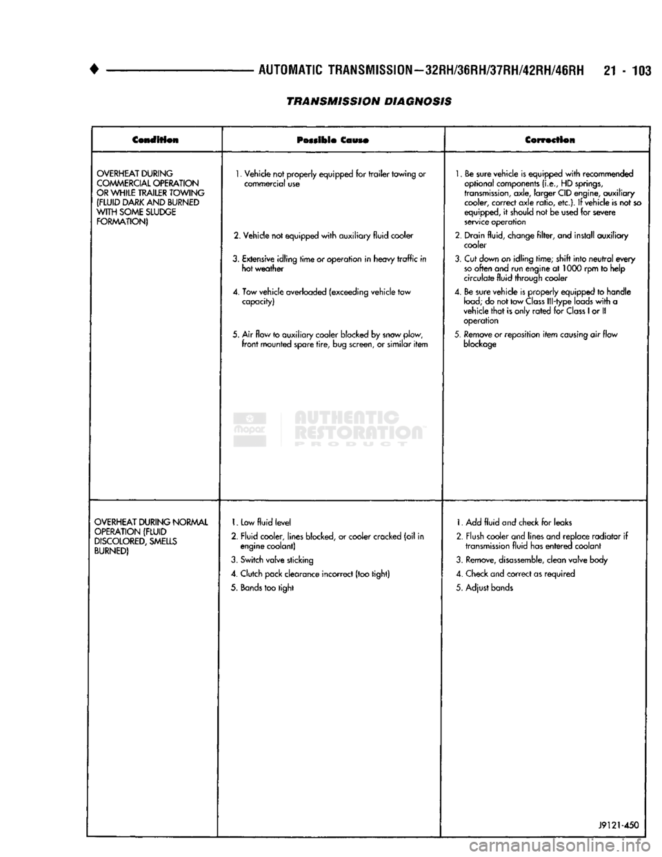
TRANSMISSION DIAGNOSIS
Condition
Possible
Couso
Correction
OVERHEAT
DURING
COMMERCIAL
OPERATION
OR
WHILE
TRAILER
TOWING
(FLUID
DARK
AND
BURNED
WITH
SOME
SLUDGE
FORMATION)
1.
Vehicle not properly equipped for
trailer
towing or
commercial use
2. Vehicle not equipped
with
auxiliary fluid cooler
3.
Extensive idling
time
or operation in heavy
traffic
in hot weather
4. Tow vehicle overloaded (exceeding vehicle tow capacity)
5. Air flow to auxiliary cooler blocked by snow plow,
front
mounted spare
tire,
bug screen, or similar
item
1.
Be sure vehicle is equipped
with
recommended
optional components
(i.e.,
HD
springs,
transmission,
axle, larger CID engine, auxiliary cooler, correct axle ratio, etc.). If vehicle is not so
equipped, it should not be used for severe
service operation
2. Drain fluid, change
filter,
and install auxiliary cooler
3.
Cut down on idling time; shift into
neutral
every
so
often and run engine at 1000 rpm to help
circulate fluid through cooler
4. Be sure vehicle is properly equipped to handle
load;
do not tow
Class
Ill-type loads
with
a
vehicle
that
is only
rated
for
Class
1
or II operation
5.
Remove or reposition
item
causing
air flow
blockage
OVERHEAT
DURING
NORMAL
OPERATION
(FLUID
DISCOLORED,
SMELLS
BURNED)
1.
Low
fluid
level
2. Fluid cooler, lines blocked, or cooler cracked (oil in engine coolant)
3.
Switch valve sticking
4. Clutch pack clearance incorrect (too tight)
5.
Bands
too tight 1. Add
fluid
and check for leaks
2. Flush cooler and lines and replace radiator if
transmission
fluid has
entered
coolant
3.
Remove,
disassemble,
clean valve body
4. Check and correct as required
5. Adjust bands
J9121-450
Page 1106 of 1502
•
AUTOMATIC
TRANSMISSION—32RH/36RH/37RH/42RH/46RH
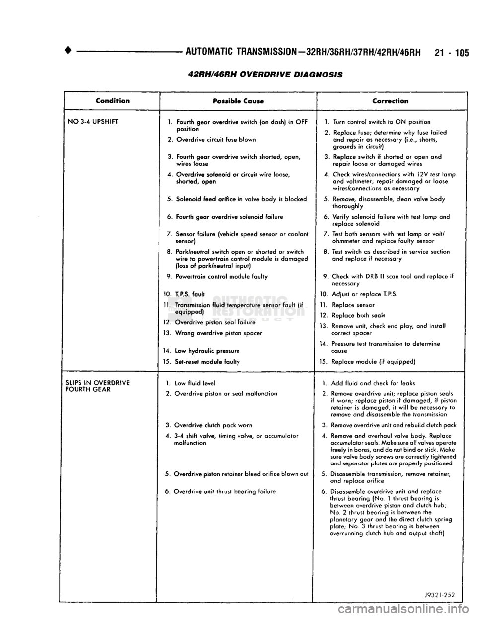
21-105 Condition
Possible
Co
use
Correction
NO
3-4 UPSHIFT
1.
Fourth
gear overdrive
switch
(on dash) in
OFF
1.
Turn control
switch
to ON position
2.
position
Overdrive
circuit
fuse
blown
2. Replace fuse; determine why fuse failed
and
repair as necessary
(i.e.,
shorts,
grounds
in
circuit)
3.
Fourth
gear
overdrive
switch
shorted, open,
wires
loose 3. Replace switch if shorted or open and
repair loose or damaged wires
4. Overdrive solenoid or circuit
wire
loose,
shorted, open 4. Check wires/connections
with
12V test lamp
and
voltmeter; repair damaged or loose
wires/connections as necessary
5. Solenoid
feed
orifice
in valve body is
blocked
5. Remove, disassemble, clean valve body
thoroughly
6.
Fourth
gear
overdrive
solenoid
failure
6. Verify solenoid
failure
with
test lamp and
replace solenoid
7.
Sensor
failure
(vehicle speed sensor or coolant
sensor)
7. Test both
sensors
with
test lamp or volt/
ohmmeter and replace
faulty
sensor
8. Park/neutral switch open or
shorted
or
switch
wire
to
powertrain
control
module is damaged
(loss
of park/neutral
input)
8. Test switch as described in service section
and
replace if necessary
9.
Powertrain
control module
faulty
9. Check
with
DRB II
scan
tool and replace if
necessary
10.
T.P.S.
fault
10. Adjust or replace
T.P.S.
11.
Transmission fluid
temperature
sensor
fault
(if equipped)
12. Overdrive piston seal
failure
13. Wrong
overdrive
piston
spacer
11.
Replace sensor
12. Replace both
seals
13. Remove unit, check end play, and install correct spacer
14.
Low
hydraulic pressure 14. Pressure test transmission to determine
cause
15. Set-reset module
faulty
15. Replace module (if equipped)
SUPS
IN
OVERDRIVE
FOURTH
GEAR
1.
2. Low
fluid
level
Overdrive piston or seal
malfunction
1.
Add fluid and check for leaks
2. Remove overdrive unit; replace piston
seals
if worn; replace piston if damaged, if piston
retainer
is damaged, it
will
be necessary to
remove and disassemble the transmission
3. Overdrive clutch pack
worn
3. Remove overdrive unit and rebuild clutch pack
4. 3-4
shift
valve,
timing
valve, or accumulator
malfunction
4. Remove and overhaul valve body. Replace
accumulator
seals.
Make sure all valves operate
freely
in bores, and do not bind or stick. Make
sure
valve body screws are correctly tightened
and
separator plates are properly positioned
5. Overdrive
piston
retainer
bleed
orifice
blown out 5. Disassemble transmission, remove
retainer,
and
replace orifice
6. Overdrive
unit
thrust
bearing
failure
6. Disassemble overdrive unit and replace
thrust bearing (No. 1 thrust bearing is between overdrive piston and clutch hub;
No.
2 thrust bearing is between the
planetary gear and the direct clutch spring plate; No. 3
thrust
bearing is between
overrunning clutch hub and output shaft)
J9321-252
42RH/46RH OVERDRIVE DIAGNOSIS
Page 1107 of 1502
21-106
AUTOMATIC
TRANSMISSION—32RH/36RH/37RH/42RH/46RH
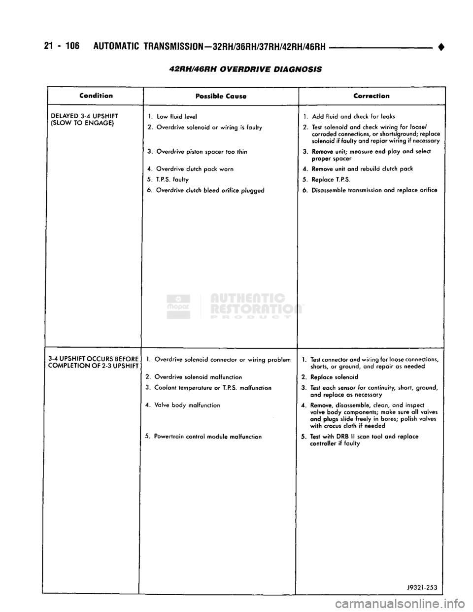
42RH/46RH OVERDRIVE DIAGNOSIS •
Condition
Possible
Cause
Correction
DELAYED
3-4
UPSHIFT
(SLOW
TO
ENGAGE)
1.
Low fluid
level
2. Overdrive solenoid or wiring is faulty
3.
Overdrive piston spacer too thin
4. Overdrive clutch pack worn
5.
T.P.S.
faulty
6. Overdrive clutch bleed orifice
plugged
1.
Add fluid and check for leaks
2. Test solenoid and check wiring for
loose/
corroded
connections,
or
shorts/ground;
replace
solenoid
if faulty and repiar wiring if
necessary
3.
Remove unit; measure end play and select proper spacer
4. Remove unit and rebuild clutch pack
5. Replace
T.P.S.
6.
Disassemble
transmission
and replace orifice
3-4
UPSHIFT
OCCURS
BEFORE
COMPLETION
OF 2-3
UPSHIFT
1.
Overdrive solenoid connector or wiring problem
2. Overdrive solenoid malfunction
3.
Coolant temperature or
T.P.S.
malfunction
4. Valve body malfunction
5. Powertrain control module malfunction
1.
Test connector and wiring for
loose
connections,
shorts,
or
ground,
and repair as needed
2. Replace solenoid
3.
Test each
sensor
for continuity, short,
ground,
and
replace as necessary
4. Remove,
disassemble,
clean, and inspect
valve
body components; make sure all valves
and
plugs
slide
freely
in bores; polish valves
with
crocus
cloth if needed
3. Test
with
DRB II
scan
tool and replace controller if faulty
J9321-253
Page 1440 of 1502
•
HEATING
AND AIR
CONDITIONING
24 - 3
DIAGNOSTIC
PROCEDURES
INDEX
page
page ..
7
General Information
3
.
. 3
Heating System Output
3
Air
Conditioning System
Blower
Motor
GENERAL
INFORMATION
The reason for owner dissatisfaction must be thor
oughly understood before any attempt is made to re
pair or replace any parts. It must be determined if
the condition is the heater system, the refrigerant system, air conditioning air flow or related to the
compressor. After confirming the condition, a func
tional test is suggested using the diagnostic charts.
After the condition has been properly diagnosed and corrected, check out the complete system to assure
that it is performing satisfactorily. The following charts have been developed for quick
reference. If the step by step method used is not com pletely understood, refer to the correct section of the Service Manual for detailed explanations.
HEATING
SYSTEM
OUTPUT
WARNING:
IF
VEHICLE
HAS
BEEN
RUN
RECENTLY,
WAIT
15
MINUTES
BEFORE
REMOVING
CAP, THEN
PLACE
A RAG
OVER
THE CAP AND
TURN
IT TO
THE
FIRST
STOP.
ALLOW
PRESSURE
TO
ESCAPE
THROUGH
THE
OVERFLOW
TUBE
AND
WHEN
THE
SYSTEM
STABILIZES,
REMOVE
THE CAP
COM
PLETELY.
Check the radiator coolant level, drive belt tension,
engine vacuum line connections, radiator air flow and radiator fan operation. Start engine and bring to
normal operating temperature (refer to Group 7,
Cooling System).
Engine coolant is provided to the heater system by
2 heater hoses. With engine idling at normal operat
ing temperature, set the heater control to maximum
heat, defrost and high blower setting. Using a test
thermometer, check the air temperature coming from
the defroster outlets (refer to Temperature Reference Chart).
Should the temperature not meet the minimum
values shown, refer to Heater Diagnosis (Mechanical)
for possible causes and corrections.
(1) Remove radiator pressure cap.
(2) Drain 1 pint of coolant from the radiator.
(3) Warm the engine to operating temperature by
idling for 20 minutes, with the pressure cap off. Idle longer if working outdoors in cold temperatures. (4) With the engine idling, place a thermometer
into the coolant in the radiator filler neck.
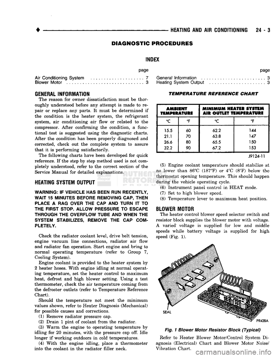
TEMPERATURE REFERENCE CHART
AMBIENT
MINIMUM
HEATER SYSTEM
TEMPERATURE
AIR OUTLET
TEMPERATURE
°C
°F
°C
°F
15.5 60 62.2 144
21.1 70
63.8 147
26.6 80
65.5 150
32.2 90 67.2 153
J9124-11
(5) Engine coolant temperature should stabilize at
no lower than 86°C (187°F) or 4°C (8°F) below the
thermostat opening temperature. This should happen during the vehicle operating cycle.
(6) Instrument panel control in HEAT mode.
(7) Set to high blower speed.
(8) Temperature lever to maximum heat position.
BLOWER
MOTOR
The heater control blower speed selector switch and
resistor block supplies the blower motor with voltage.
A varied voltage is supplied for low and middle speeds while battery voltage is supplied for high
speed (Fig. 1).
Fig.
1
Blower
Motor
Resistor
Block
(Typical)
Refer to Heater Blower Motor/Control System Di
agnosis (Electrical) Chart and Blower Motor Noise/
Vibration Chart.