1993 DODGE TRUCK oil temperature
[x] Cancel search: oil temperaturePage 298 of 1502
•
COOLING
SYSTEM
7 - 27 down to -67.7°C (-90°F). A higher percentage will
freeze at a warmer temperature. Also, a higher per centage of antifreeze can cause the engine to over
heat because specific heat of antifreeze is lower than
that of water.
CAUTION:
Richer
antifreeze
mixtures
cannot
be
measured
with
normal
field
equipment
and can
cause
problems
associated
with 100
percent
ethyl
ene-glycol.
COOLANT SELECTION-ADDITIVES The presence of aluminum components in the cool
ing system requires strict corrosion protection. Main
tain coolant at specified level with a mixture of ethylene-glycol based antifreeze and water. Only use an antifreeze containing ALUGARD 340-2
™
such as
Mopar Antifreeze. If coolant becomes contaminated
or looses color, drain and flush cooling system and
fill with correctly mixed solution.
A 0.25 percent emulsifiable oil is added to the ra
diator at the factory to prevent solder corrosion.
CAUTION:
Do not use
coolant
additives
that are
claimed
to
improve
engine
cooling.
COOLANT SERVICE-EXCEPT DIESEL It is recommended that the cooling system be
drained and flushed at 84,000 kilometers (52,500
miles) or 3 years, whichever occurs first. Then every
two years or 48,000 kilometers (30,000 miles), which ever occurs first.
COOLANT SERVICE-DIESEL ENGINE It is recommended that the cooling system be
drained and flushed every 24 months or 38,600 kilo meters (24,000 miles), whichever occurs first.
COOLANT LEVEL CHECK-ROUTINE Do not remove radiator cap for routine coolant
level inspections. The coolant level can be checked at the coolant reserve/overflow tank.
The coolant reserve/overflow system provides a
quick visual method for determining the coolant
level without removing the radiator pressure cap.
With engine idling and at normal operating temper ature, observe coolant level in coolant reserve/over
flow tank. The coolant level should be between the MIN and MAX (diesel engine) or ADD and FULL (gas engines) marks.
ADDING ADDITIONAL COOLANT-ROUTINE Do not remove the radiator cap to add coolant
to the system. When adding coolant to maintain the correct level, do so at the coolant reserve/overflow
tank with a 50/50 mixture of ethylene-glycol anti
freeze (containing Alugard 340-2 ™) and water. Re move the radiator cap only for testing or when
refilling the system after service. Removing cap un necessarily can cause loss of coolant and allow air to
enter system. This produces corrosion.
COOLANT LEVEL CHECK-SERVICE The cooling system is closed and designed to main
tain coolant level to the top of the radiator.
WARNING:
DO
NOT OPEN RADIATOR DRAINCOCK
WITH
ENGINE RUNNING
OR
WHILE ENGINE
IS HOT
AND COOLING
SYSTEM
IS
UNDER
PRESSURE.
When vehicle servicing requires a coolant level
check in the radiator, drain several ounces of coolant
from the radiator drain cock. Do this while observing
the coolant reserve/overflow system tank. The cool ant level in the reserve/overflow tank should drop
slightly. If not, inspect for a leak between radiator and coolant reserve/overflow system connection. Re
move radiator cap. The coolant level should be to the
top of the radiator. If not and if coolant level in re serve/overflow tank is at the ADD (gas engines) or
MIN (5.9L diesel engine) mark, check for:
• An air leak in the coolant reserve/overflow tank
• An air leak in the radiator filler neck
• Leak in the pressure cap seal to the radiator filler
neck
LOW COOLANT LEVEL-AERATION If the coolant level in the radiator drops below the
top of the radiator core tubes, air will enter the sys
tem. Low coolant level can cause the thermostat pellet
to be suspended in air instead of coolant. This will cause the thermostat to open later, which in turn causes higher coolant temperature. Air trapped in
cooling system also reduces the amount of coolant
circulating in the heater core. This may result in low
heat output.
DEAERATION As the engine operates, air trapped in the cooling
system gathers under the radiator cap. The next time
engine is operated, thermal expansion of coolant will
push trapped air past radiator cap into coolant re serve/overflow tank. Here it escapes to atmosphere in
the tank. When engine cools down the coolant, it will
be drawn from reserve/overflow tank into radiator to replace removed air.
DRAINING
COOLING
SYSTEM
WARNING:
DO NOT
REMOVE
THE
CYLINDER BLOCK DRAIN PLUGS
OR
LOOSEN THE RADIATOR
DRAIN PLUG
WITH
SYSTEM
HOT AND
UNDER
PRESSURE.
SERIOUS BURNS
FROM
COOLANT
CAN OCCUR.
Page 299 of 1502
7 - 28
COOLING SYSTEM
DO NOT WASTE reusable coolant. If the solution
is clean, drain the coolant into a clean container for
reuse.
(1) Start the engine and place the heater control
temperature selector in the Full On position. Engine vacuum is needed to actuate the heater controls.
(2) Turn the ignition off. (3) Do not remove radiator cap when draining cool
ant from reserve/overflow tank. Open radiator drain
plug and when tank is empty, remove radiator cap. If
the coolant reserve/overflow tank does not drain, re fer to the Testing Cooling System for Leaks section
in this group. The coolant need not be removed from
tank unless the system is being refilled with fresh mixture.
(4) On vehicles equipped with gas powered en
gines,
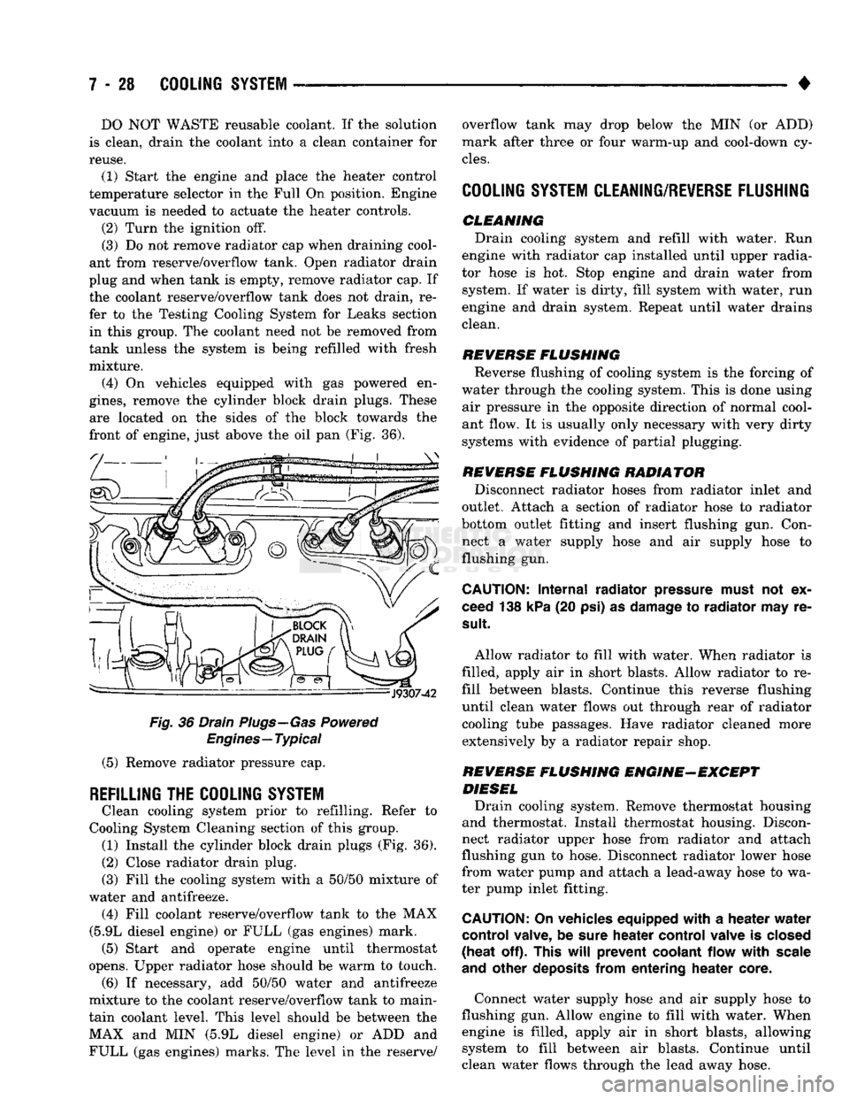
remove the cylinder block drain plugs. These are located on the sides of the block towards the
front of engine, just above the oil pan (Fig. 36).
Fig.
36 Drain Plugs—Gas Powered
Engines—Typical
(5) Remove radiator pressure cap.
REFILLING
THE
COOLING SYSTEM
Clean cooling system prior to refilling. Refer to
Cooling System Cleaning section of this group. (1) Install the cylinder block drain plugs (Fig. 36).
(2)
Close radiator drain plug.
(3) Fill the cooling system with a 50/50 mixture of
water and antifreeze. (4) Fill coolant reserve/overflow tank to the MAX
(5.9L diesel engine) or FULL (gas engines) mark. (5) Start and operate engine until thermostat
opens. Upper radiator hose should be warm to touch. (6) If necessary, add 50/50 water and antifreeze
mixture to the coolant reserve/overflow tank to main
tain coolant level. This level should be between the MAX and MIN (5.9L diesel engine) or ADD and FULL (gas engines) marks. The level in the reserve/ overflow tank may drop below the MIN (or ADD)
mark after three or four warm-up and cool-down cy
cles.
COOLING SYSTEM CLEANING/REVERSE FLUSHING
CLEMMING Drain cooling system and refill with water. Run
engine with radiator cap installed until upper radia
tor hose is hot. Stop engine and drain water from system. If water is dirty, fill system with water, run
engine and drain system. Repeat until water drains
clean.
REVERSE
FLUSHING
Reverse flushing of cooling system is the forcing of
water through the cooling system. This is done using air pressure in the opposite direction of normal cool
ant flow. It is usually only necessary with very dirty
systems with evidence of partial plugging.
REVERSE
FLUSHING
RADIATOR Disconnect radiator hoses from radiator inlet and
outlet. Attach a section of radiator hose to radiator
bottom outlet fitting and insert flushing gun. Con
nect a water supply hose and air supply hose to flushing gun.
CAUTION:
Internal
radiator
pressure must
not'ex
ceed 138 kPa (20 psi) as damage to
radiator
may re
sult
Allow radiator to fill with water. When radiator is
filled, apply air in short blasts. Allow radiator to re
fill between blasts. Continue this reverse flushing
until clean water flows out through rear of radiator cooling tube passages. Have radiator cleaned more extensively by a radiator repair shop.
REVERSE
FLUSHING
ENGINE-EXCEPT DIESEL Drain cooling system. Remove thermostat housing
and thermostat. Install thermostat housing. Discon
nect radiator upper hose from radiator and attach
flushing gun to hose. Disconnect radiator lower hose
from water pump and attach a lead-away hose to wa
ter pump inlet fitting.
CAUTION;
On vehicles equipped
with
a
heater
water
control
valve, be sure
heater
control
valve is closed
(heat
off). This
will
prevent
coolant
flow
with
scale
and
other
deposits
from
entering
heater
core.
Connect water supply hose and air supply hose to
flushing gun. Allow engine to fill with water. When engine is filled, apply air in short blasts, allowing system to fill between air blasts. Continue until
clean water flows through the lead away hose.
Page 302 of 1502
•
COOLING
SYSTEM
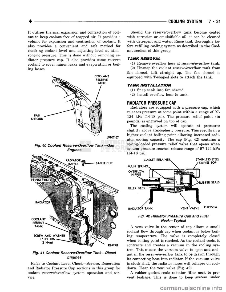
7 - 31 It utilizes thermal expansion and contraction of cool
ant to keep coolant free of trapped air. It provides a
volume for expansion and contraction of coolant. It
also provides a convenient and safe method for
checking coolant level and adjusting level at atmo
spheric pressure. This is done without removing ra
diator pressure cap. It also provides some reserve
coolant to cover minor leaks and evaporation or boil
ing losses.
FAN
SHROUD
J9107-67
Fig.
40 Coolant Reserve/Overflow Tank—Gas
Engines
Fig.
41 Coolant Reserve/Overflow Tank—Diesel
Engines
Refer to Coolant Level Check—Service, Deaeration
and Radiator Pressure Cap sections in this group for
coolant reserve/overflow system operation and ser
vice.
Should the reserve/overflow tank become coated
with corrosion or emulsifiable oil, it can be cleaned
with detergent and water. Rinse tank thoroughly be
fore refilling cooling system as described in the Cool ant section of this group.
TANK REMOVAL
(1) Remove overflow hose at reserve/overflow tank.
(2) Unsnap the coolant reserve/overflow tank from
fan shroud. Lift straight up. The fan shroud is
equipped with T-shaped slots to attach the tank.
TANK INSTALLATION
(1) Snap tank into fan shroud.
(2) Install overflow hose to tank.
RADIATOR
PRESSURE
CAP
Radiators are equipped with a pressure cap, which
releases pressure at some point within a range of 97- 124 kPa (14-18 psi). The pressure relief point (in
pounds) is engraved on top of cap. The cooling system will operate at pressures
slightly above atmospheric pressure. This results in a
higher coolant boiling point allowing increased radi ator cooling capacity. The cap (Fig. 42) contains a
spring-loaded pressure relief valve that opens when
system pressure reaches release range of 97-124 kPa (14-18 psi).
Fig.
42 Radiator
Pressure
Cap and
Filler
Neck—Typical
A vent valve in the center of cap allows a small
coolant flow through cap when coolant is below boil
ing temperature. The valve is completely closed
when boiling point is reached. As the coolant cools, it contracts and creates a vacuum in the cooling sys
tem. This causes the vacuum valve to open and cool ant in the reserve/overflow tank to be drawn through
its connecting hose into radiator. If the vacuum valve
is stuck shut, the radiator hoses will collapse on cool-
down. Clean the vent valve (Fig. 42).
A rubber gasket seals radiator filler neck to pre
vent leakage. This is done to keep system under
Page 304 of 1502
•
COOLING
SYSTEM
7 - 33 The radiator supplies sufficient heat transfer to
cool the engine and automatic transmission (if equipped).
RADIATOR COOLANT FLOW CHECK
Use the following procedure to determine if coolant
is flowing through the cooling system.
(1) Idle engine until operating temperature is
reached. If the upper radiator hose is warm to the
touch, the thermostat is opening and coolant is flow ing to the radiator.
WARNING:
HOT,
PRESSURIZED COOLANT
CAN
CAUSE
INJURY
BY
SCALDING. USING
A
RAG
TO
COVER
THE
RADIATOR
PRESSURE
CAP,
OPEN RADIATOR
CAP
SLOWLY
TO THE
FIRST STOP.
THIS
WILL
ALLOW
ANY
BUILT-UP
PRESSURE
TO
VENT
TO
THE
RESERVE/OVERFLOW TANK. AFTER
PRESSURE
BUILD-UP
HAS
BEEN RELEASED,
RE
MOVE
CAP
FROM FILLER NECK.
(2) Drain a small amount of coolant from the radi
ator until the ends of the radiator tubes are visible
through the filler neck. Idle the engine at normal op
erating temperature. If coolant is flowing past the
exposed tubes, the coolant is circulating.
RADIATOR REMOVAL-EXCEPT DIESEL
(1) Disconnect negative battery cable from battery.
WARNING;
DO NOT
REMOVE
THE
CYLINDER BLOCK DRAIN PLUGS
OR
LOOSEN
THE
RADIATOR
DRAINCOCK
WITH
THE
SYSTEM
HOT AND
UNDER
PRESSURE.
SERIOUS BURNS FROM COOLANT
CAN OCCUR.
(2) Drain the cooling system. Refer to Draining
Cooling System.
(3) Disconnect throttle cable from clip at radiator
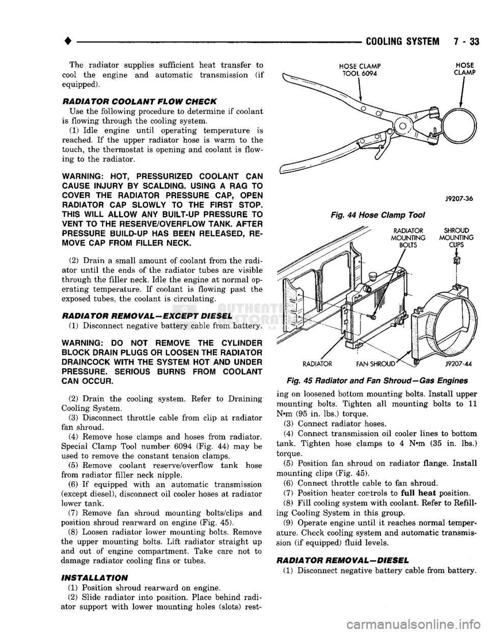
fan shroud. (4) Remove hose clamps and hoses from radiator.
Special Clamp Tool number 6094 (Fig. 44) may be
used to remove the constant tension clamps.
(5) Remove coolant reserve/overflow tank hose
from radiator filler neck nipple.
(6) If equipped with an automatic transmission
(except diesel), disconnect oil cooler hoses at radiator
lower tank.
(7) Remove fan shroud mounting bolts/clips and
position shroud rearward on engine (Fig. 45). (8) Loosen radiator lower mounting bolts. Remove
the upper mounting bolts. Lift radiator straight up and out of engine compartment. Take care not to
damage radiator cooling fins or tubes.
INSTALLATION
(1) Position shroud rearward on engine.
(2) Slide radiator into position. Place behind radi
ator support with lower mounting holes (slots) rest-
HOSE
CLAMP
TOOL
6094
HOSE
CLAMP
J9207-36
Fig.
44
Hose
Clamp
Tool
RADIATOR SHROUD
MOUNTING MOUNTING
BOLTS
CUPS
RADIATOR
V1
FAN SHROUD^
J9207-44
Fig.
45 Radiator and Fan
Shroud—Gas Engines
ing on loosened bottom mounting bolts. Install upper
mounting bolts. Tighten all mounting bolts to 11
N*m (95 in. lbs.) torque.
(3) Connect radiator hoses.
(4) Connect transmission oil cooler lines to bottom
tank. Tighten hose clamps to 4 N#m (35 in. lbs.)
torque.
(5) Position fan shroud on radiator flange. Install
mounting clips (Fig. 45).
(6) Connect throttle cable to fan shroud.
(7) Position heater controls to full heat position.
(8) Fill cooling system with coolant. Refer to Refill
ing Cooling System in this group.
(9) Operate engine until it reaches normal temper
ature. Check cooling system and automatic transmis
sion (if equipped) fluid levels.
RADIATOR REMOVAL-DIESEL
(1) Disconnect negative battery cable from battery.
Page 309 of 1502
7 - 38
COOLING
SYSTEM
•
WARNING:
DO NOT
ATTEMPT
TO
BEND
OR
STRAIGHTEN
FAN
BLADES
IF
NOT WITHIN
SPECI
FICATIONS.
(4) Inspect fan assembly for cracks, bends, loose
rivets or broken welds. Replace fan if any damage is
found.
CAUTION; If the fan
blade assembly
is
replaced
be
cause
of
mechanical damage,
the fan
pulley
and
viscous
fan
drive should also
be
inspected.
These
components
could have been damaged
due to ex
cessive
vibration.
INSTALLATION
(1) Install fan blade assembly to viscous fan drive.
Tighten mounting bolts.
(2) Position the fan shroud and fan blade/viscous
fan drive to the vehicle as an assembly.
(3) Install viscous fan drive assembly on fan hub
shaft. Tighten mounting nut to 57 N*m (42 ft. lbs.)
torque.
(4) Install fan shroud bolts.
(5) Install battery cable to battery.
VISCOUS
FAN
DRIVE
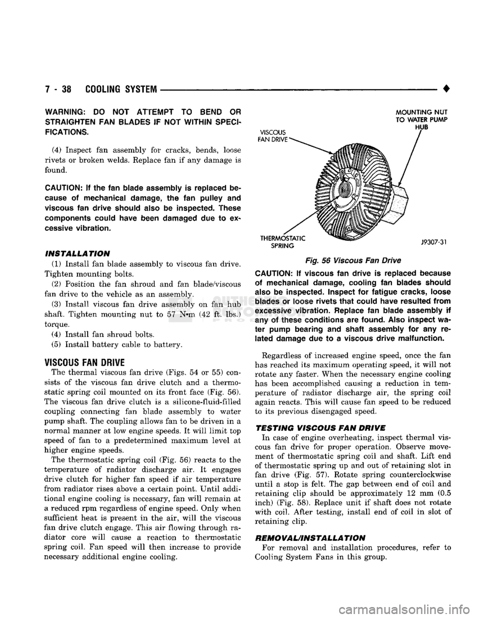
The thermal viscous fan drive (Figs. 54 or 55) con
sists of the viscous fan drive clutch and a thermo
static spring coil mounted on its front face (Fig. 56).
The viscous fan drive clutch is a silicone-fluid-filled coupling connecting fan blade assembly to water
pump shaft. The coupling allows fan to be driven in a normal manner at low engine speeds. It will limit top
speed of fan to a predetermined maximum level at
higher engine speeds.
The thermostatic spring coil (Fig. 56) reacts to the
temperature of radiator discharge air. It engages drive clutch for higher fan speed if air temperature
from radiator rises above a certain point. Until addi
tional engine cooling is necessary, fan will remain at a reduced rpm regardless of engine speed. Only when
sufficient heat is present in the air, will the viscous
fan drive clutch engage. This air flowing through ra diator core will cause a reaction to thermostatic spring coil. Fan speed will then increase to provide
necessary additional engine cooling.
MOUNTING
NUT
TO WATER PUMP
Fig.
56
Viscous
Fan Drive CAUTION; If
viscous
fan
drive
is
replaced because
of mechanical damage, cooling
fan
blades should
also
be
inspected. Inspect
for
fatigue cracks, loose
blades
or
loose rivets
that
could have resulted
from
excessive
vibration. Replace
fan
blade assembly
if
any
of
these conditions
are
found.
Also
inspect
wa
ter
pump bearing
and
shaft assembly
for any re
lated
damage
due to a
viscous
drive malfunction.
Regardless of increased engine speed, once the fan
has reached its maximum operating speed, it will not
rotate any faster. When the necessary engine cooling
has been accomplished causing a reduction in tem perature of radiator discharge air, the spring coil again reacts. This will cause fan speed to be reduced
to its previous disengaged speed.
TESTING VISCOUS FAN DRIVE In case of engine overheating, inspect thermal vis
cous fan drive for proper operation. Observe move
ment of thermostatic spring coil and shaft. Lift end
of thermostatic spring up and out of retaining slot in
fan drive (Fig. 57). Rotate spring counterclockwise until a stop is felt. The gap between end of coil and
retaining clip should be approximately 12 mm (0.5 inch) (Fig. 58). Replace unit if shaft does not rotate
with coil. After testing, install end of coil in slot of retaining clip.
REMOVAUINSTALLA
TION For removal and installation procedures, refer to
Cooling System Fans in this group.
Page 327 of 1502
8A
- 6
ELECTRICAL
•
Fig.
10
Load
50%
Cold
Crank
Rating Note Voltage
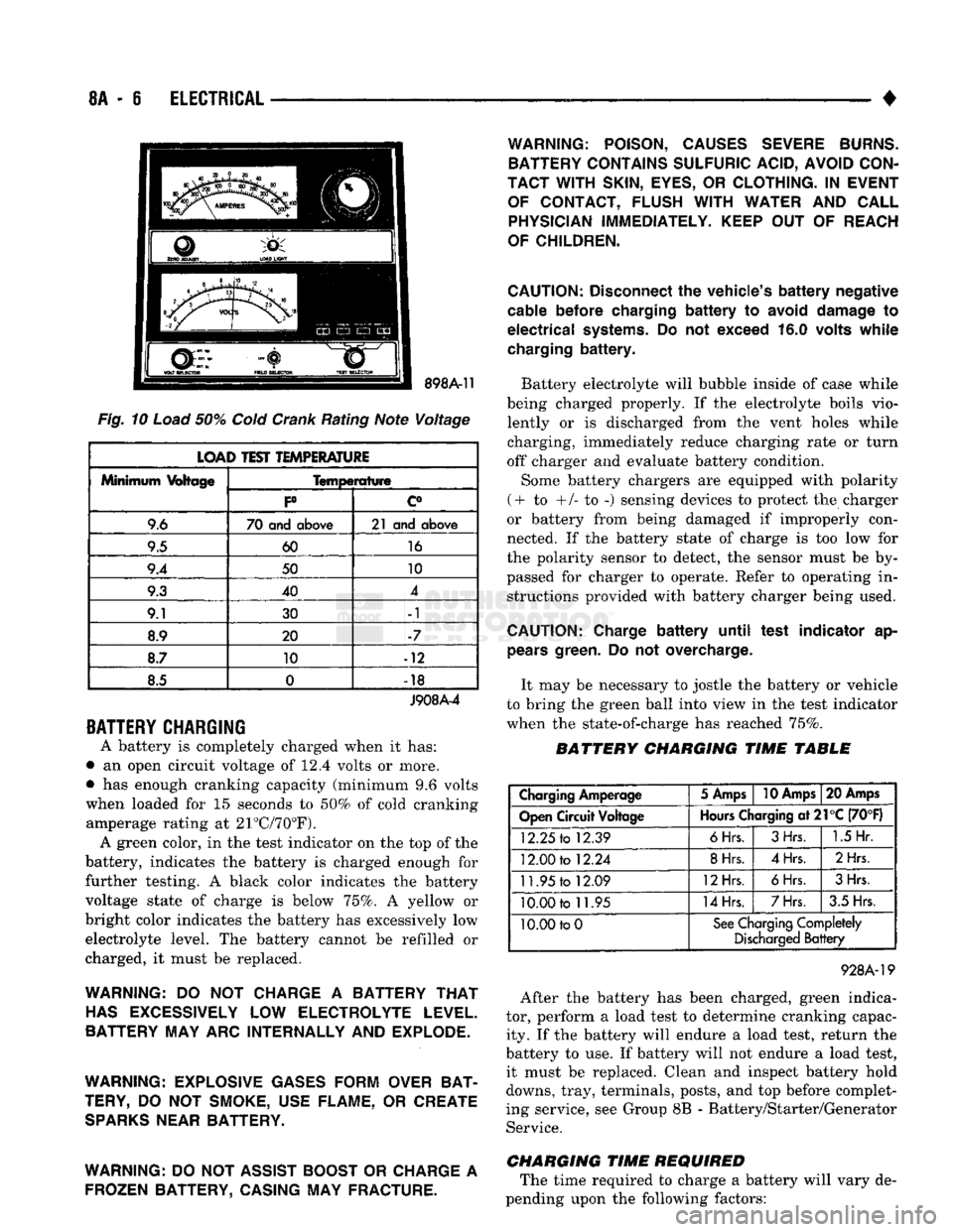
LOAD TEST TEMPERATURE
Minimum
Voltage
Temperature
Minimum
Voltage
P c°
9.6 70 and
above
21 and
above
9.5 60
16
9.4 50 10
9.3 40 4
9.1 30 -1
8.9 20 -7
8.7 10 -12
8.5 0
•
18
J908A-4
BATTERY
CHARGING
A battery is completely charged when it has:
• an open circuit voltage of 12.4 volts or more.
• has enough cranking capacity (minimum 9.6 volts
when loaded for 15 seconds to 50% of cold cranking amperage rating at 21°C/70°F). A green color, in the test indicator on the top of the
battery, indicates the battery is charged enough for
further testing. A black color indicates the battery
voltage state of charge is below 75%. A yellow or
bright color indicates the battery has excessively low electrolyte level. The battery cannot be refilled or
charged, it must be replaced.
WARNING:
DO NOT
CHARGE
A
BATTERY
THAT
HAS
EXCESSIVELY
LOW
ELECTROLYTE LEVEL.
BATTERY MAY ARC INTERNALLY AND EXPLODE.
WARNING: EXPLOSIVE GASES FORM OVER BAT
TERY,
DO NOT
SMOKE, USE FLAME,
OR
CREATE
SPARKS
NEAR BATTERY.
WARNING:
DO
NOT ASSIST BOOST
OR
CHARGE
A
FROZEN BATTERY, CASING MAY FRACTURE. WARNING: POISON, CAUSES SEVERE BURNS.
BATTERY CONTAINS SULFURIC ACID, AVOID CON
TACT WITH
SKIN,
EYES,
OR
CLOTHING.
IN
EVENT OF CONTACT, FLUSH
WITH
WATER
AND
CALL PHYSICIAN IMMEDIATELY. KEEP
OUT OF
REACH
OF CHILDREN.
CAUTION:
Disconnect
the
vehicle's
battery
negative
cable
before
charging
battery to
avoid
damage
to
electrical
systems.
Do not
exceed
16.0
volts
while
charging
battery.
Battery electrolyte will bubble inside of case while
being charged properly. If the electrolyte boils vio lently or is discharged from the vent holes while
charging, immediately reduce charging rate or turn
off charger and evaluate battery condition.
Some battery chargers are equipped with polarity
(+ to +/- to -) sensing devices to protect the charger
or battery from being damaged if improperly con
nected. If the battery state of charge is too low for
the polarity sensor to detect, the sensor must be by
passed for charger to operate. Refer to operating in structions provided with battery charger being used.
CAUTION:
Charge
battery
until
test
indicator
ap
pears
green.
Do not
overcharge.
It may be necessary to jostle the battery or vehicle
to bring the green ball into view in the test indicator
when the state-of-charge has reached 75%.
BATTERY CHARGING TIME TABLE
Charging
Amperage
5 Amps
10 Amps
20 Amps
Open
Circuit
Voltage
Hours
Charging
at21°C
(70°F)
12.25
to
12.39
6Hrs.
3Hrs.
1.5
Hr.
12.00
to
12.24
8Hrs.
4Hrs.
2Hrs
11.95
to
12.09
12Hrs.
6Hrs.
3Hrs.
10.00
to
11.95
14Hrs.
7Hrs.
3.5 Hrs.
10.00 to
0
See
Charging
Completely
Discharged
Battery
928A-19
After the battery has been charged, green indica
tor, perform a load test to determine cranking capac ity. If the battery will endure a load test, return the
battery to use. If battery will not endure a load test, it must be replaced. Clean and inspect battery hold
downs, tray, terminals, posts, and top before complet
ing service, see Group 8B - Battery/Starter/Generator Service.
CHARGING TIME REQUIRED The time required to charge a battery will vary de
pending upon the following factors:
Page 339 of 1502
8A
- 18
ELECTRICAL
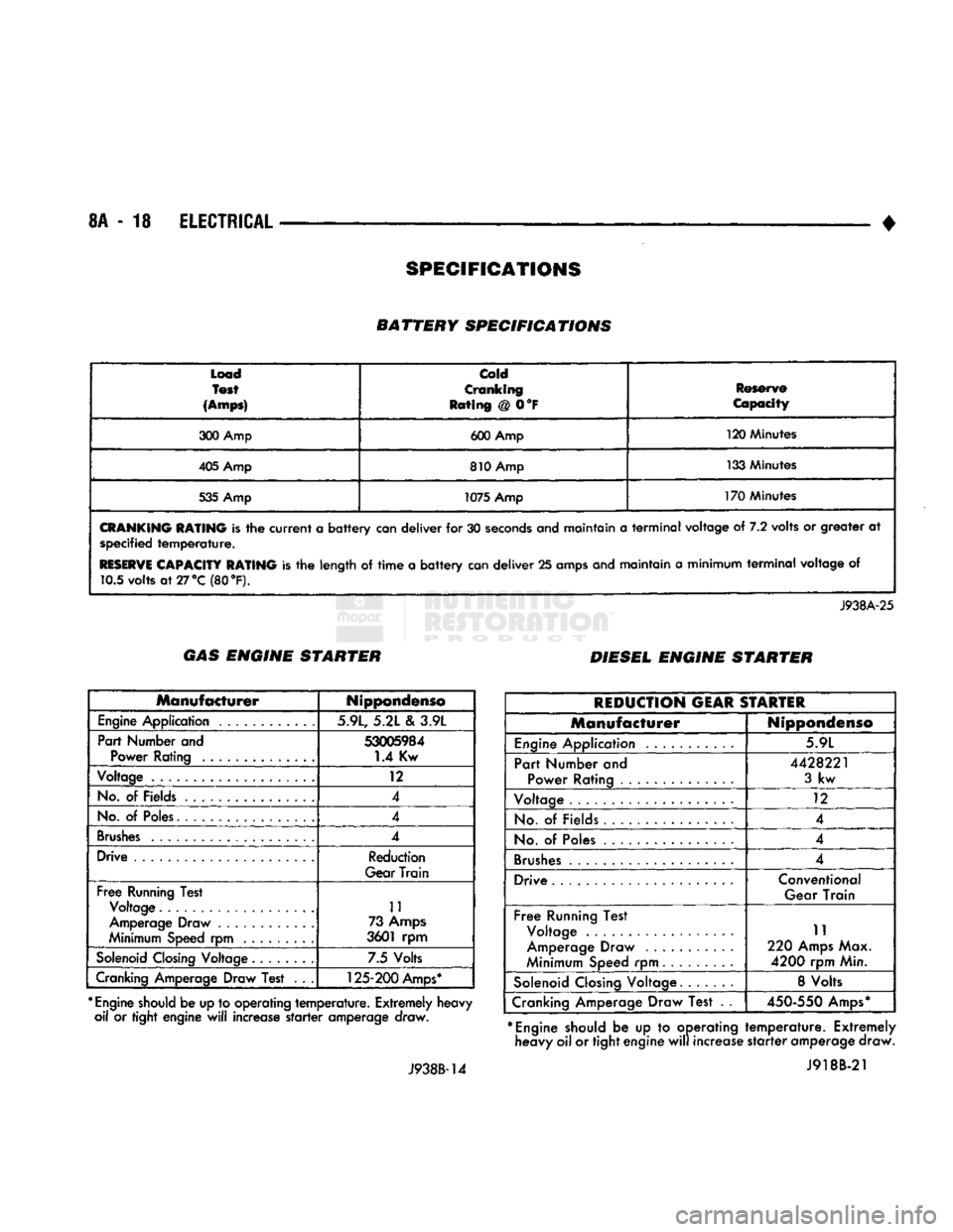
• BATTERY SPECIFICATIONS
Load
Test
(Amps)
Cold
Cranking
Rating @ 0°F Reserve
Capacity
300 Amp 600 Amp 120 Minutes
405 Amp 810 Amp 133 Minutes
535 Amp 1075 Amp 170 Minutes
CRANKING
RATING
is the
current
a
battery
can deliver for 30
seconds
and maintain a
terminal
voltage of 7.2 volts or greater at specified
temperature.
RESERVE
CAPACITY RATING
is the length of
time
a
battery
can deliver 25 amps and maintain a minimum
terminal
voltage of 10.5 volts
at27°C
(80 °F).
J938A-25 GAS ENGINE STARTER
DIESEL ENGINE STARTER
Manufacturer
Nippondenso
Engine
Application 5.9L, 5.21 e\ 3.9L
Part Number and
53005984
Power Rating 1.4 Kw
Voltage 12
No.
of Fields 4
No.
of
Poles.
4
Brushes
4
Drive Reduction
Gear Train
Free
Running Test Voltage 11
Amperage Draw ............ 73
Amps
Minimum Speed rpm 3601 rpm
Solenoid
Closing
Voltage 7.5 Volts
Cranking Amperage Draw Test . . .
125-200
Amps*
*
Engine
should
be up to operating
temperature.
Extremely heavy oil or tight engine
will
increase
starter
amperage draw.
J938B-14
REDUCTION
GEAR
STARTER
Manufacturer
Nippondenso
Engine
Application 5.9L
Part Number and Power Rating ..............
4428221
3
kw
Voltage 12
No.
of Fields 4
No.
of
Poles
4
Brushes
.................... 4
Drive Conventional
Gear Train
Free
Running Test Voltage .
Amperage Draw
Minimum Speed rpm 11
220
Amps
Max.
4200
rpm Min.
Solenoid
Closing
Voltage. 8 Volts
Cranking Amperage Draw Test . .
450-550
Amps*
*
Engine
should be up to operating heavy oil or tight engine
will
increase
temperature.
Extremely
starter
amperage draw. J918B-21
SPECIFICATIONS
Page 350 of 1502
•
BATTERY/STARTER/GENERATOR
SERVICE
8B - 9
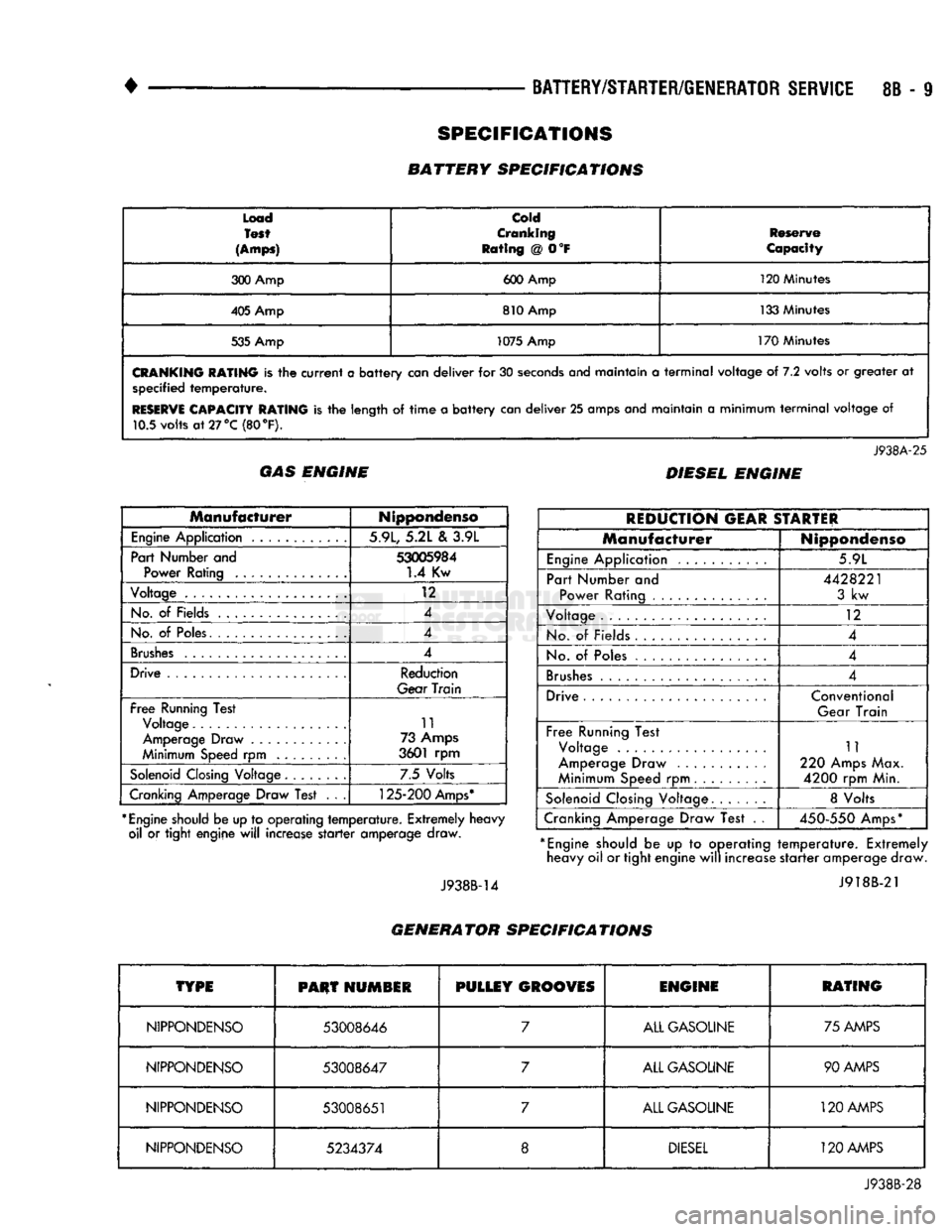
Load
Test
(Amps)
cold
Cranking
Rating
@ 0°F
Reserve
Capacity
300 Amp 600 Amp 120 Minutes
405 Amp 810 Amp 133 Minutes
535 Amp 1075 Amp
170 Minutes
CRANKING
RATING
is the
current
a
battery
can
deliver
for 30
seconds
anej
maintain
a
terminal
voltage
of 7.2
volts
or
greater
at
specified
temperature.
RESERVE
CAPACITY RATING
is the
length
of
time
a
battery
can
deliver
25
amps and maintain
a
minimum
terminal
voltage
of
10.5 volts
at
27 °C (80
°F).
J938A-25
GAS ENGINE DIESEL ENGINE
Manufacturer
Nippondenso
Engine
Application 5.9L, 5.2L
&
3.9L
Part Number and
53005984
Power Rating
1.4
Kw
Voltage
12
No.
of
Fields 4
No.
of
Poles. 4
Brushes
4
Drive Reduction
Gear
Train
Free
Running Test Voltage 11
Amperage Draw 73 Amps
Minimum Speed
rpm
3601
rpm
Solenoid
Closing Voltage 7.5 Volts
Cranking Amperage Draw Test
. . .
125-200
Amps*
*
Engine
should be up to operating
temperature.
Extremely heavy oil
or
tight engine
will
increase
starter
amperage draw.
J938B-14
REDUCTION
GEAR
STARTER
Manufacturer
Nippondenso
Engine
Application 5.9L
Part Number
and
Power Rating
4428221
3
kw
Voltage
12
No.
of
Fields
4
No.
of
Poles 4
Brushes
4
Drive Conventional
Gear Train
Free
Running Test Voltage
Amperage Draw
Minimum Speed
rpm
11
220 Amps Max.
4200
rpm Min.
Solenoid
Closing Voltage 8 Volts
Cranking Amperage Draw Test
. .
450-550
Amps*
*
Engine
should
be up to
operating
temperature.
Extremely heavy oil or tight engine
will
increase
starter
amperage draw.
J918B-21
GENERATOR SPECIFICATIONS
TYPE
PHUT
HUMSIR
PULLEY
GROOVES
ENGINE
RATING
NIPPONDENSO
53008646
7
ALL GASOLINE 75 AMPS
NIPPONDENSO
53008647
7
ALL GASOLINE 90 AMPS
NIPPONDENSO
53008651
7
ALL GASOLINE
120
AMPS
NIPPONDENSO
5234374
8
DIESEL
120 AMPS
J938B-28
SPECIFICATIONS
BATTERY SPECIFICATIONS