1993 DODGE TRUCK cycling switch
[x] Cancel search: cycling switchPage 1453 of 1502
24 - 16 HEATING AND AIR CONDITIONING
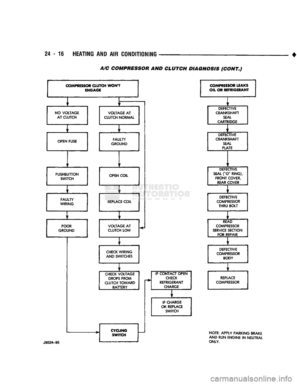
A/C
COMPRESSOR AND CLUTCH DIAGNOSIS (CONT.)
COMPRESSOR
CLUTCH
WON'T
ENGAGE
f
f
NO
VOLTAGE
VOLTAGE
AT
AT CLUTCH CLUTCH
NORMAL
f t
OPEN FUSE FAULTY
GROUND
f
1
PUSHBUTTON SWITCH OPEN COIL
f
FAULTY
WIRING
REPLACE
COIL
f
r
POOR
VOLTAGE
AT
GROUND CLUTCH LOW
f
CHECK
WIRING
AND SWITCHES
f
CHECK
VOLTAGE
DROPS
FROM
CLUTCH TOWARD BATTERY
CYCLING SWITCH IF CONTACT OPEN
CHECK
REFRIGERANT
CHARGE
IF CHARGE
OK REPLACE SWITCH
COMPRESSOR
LEAKS
OIL OR REFRIGERANT
DEFECTIVE
CRANKSHAFT
SEAL
CARTRIDGE
DEFECTIVE
CRANKSHAFT
SEAL
PLATE
DEFECTIVE
SEAL
("O' RING),
FRONT
COVER,
REAR
COVER
DEFECTIVE
COMPRESSOR
THRU
BOLT
READ
COMPRESSOR
SERVICE
SECTION FOR REPAIR
DEFECTIVE
COMPRESSOR
BODY
REPLACE
COMPRESSOR
NOTE: APPLY PARKING BRAKE
AND RUN ENGINE
IN
NEUTRAL
ONLY.
Page 1457 of 1502
24
- 20
HEATING
AND AIR
CONDITIONING
• (3) Turn
3
refrigerant manifold valves completely
clockwise
to
puncture
the
cans
and
close
the
mani
fold valves.
(4) Purge
the air
from
the
charging line
by
loosen
ing
the
charging hose
at the
manifold gauge
set and
turn
one of the
refrigerant valves counterclockwise. When
the
refrigerant
gas
starts escaping from
the
loose connection, tighten
the
hose.
(5) Fully open
all 3
refrigerant manifold valves
and place
the
cans
of
refrigerant into
a pan
contain
ing 52°C (125°F) water.
The
water will warm
the
charging
can and aid in the
transfer
of the
charge
into
the
system.
(6) Start
the
engine
and
move
the
controls
to A/C
low blower position.
The electronic temperature cycling switch will pre
vent
the
clutch from engaging until refrigerant
is
added
to the
system.
If the
clutch does engage,
re
place
the
switch before proceeding
any
further. (7) Charge through
the
suction side
of the
system
by slowly opening
the
suction manifold valve. Adjust
the valve
as
necessary
so
charging pressure does
not
exceed
345
kPag
(50
psig). Maintain
the
temperature
of
the
water
in the pan by
adding warm water
as
necessary. (8) Adjust
the
engine speed
to a
fast idle
of
approx
imately
1,300 RPM.
(9) When
all 3
cans
of
refrigerant
are
completely
empty, close
the
manifold gauge
set
valves
and re
frigerant manifold valves. The maximum refrigerant charge
is 44 oz.
REFRIGERANT
LEAK REPAIR PROCEDURE
LOST CHARGE If
the
system
has
lost
all
charge
due to a
leak: (1) Evacuate
the
system.
(2) Charge
the
system with approximately
1
pound
of refrigerant. (3) Locate
all
leaks.
(4) Repair
all
leaks.
(5) Replace filter-drier bottle.
CAUTION:
Replacement
filter-drier
units
must
be
sealed
while
in
storage.
The
drier
used
in
these
units
absorbs
and
traps
moisture
quickly
upon
ex
posure
to the
atmosphere.
When
installing
a
drier,
have
all
tools
and
supplies ready
for
quick
reas
sembly
to
avoid keeping
the
system open
any
longer
than
necessary.
(6) Check system
oil
level. (7) Evacuate
and
charge
the
system.
LOW CHARGE If
the
system
has not
lost
all of its
refrigerant
charge; locate
and
repair
all
leaks.
If it is
necessary
to increase
the
system pressure
to
find
the
leak
(be
cause
of an
especially
low
charge),
add 230 g (1/2 lb)
of refrigerant.
If
there
has
been
a
significant
oil
loss,
check
the
system
oil
level.
If
leak repair
was
possible
without discharging system
and an oil
level check
was
not
necessary,
use
procedure
for
correcting
low
refrigerant level.
CORRECTING
LOW
REFRIGERANT LEVEL
Since
the
refrigeration system
is
completely sealed,
the refrigerant level will
not be low
unless there
is a
leak
in the
system. Before adding refrigerant where
the
cause
of a low
level
is not
known,
the
system should
be
tested
for
leaks.
Assuming that leaks have been corrected without
discharging
the
system, proceed with partial charge.
Install
and
connect manifold gauge
set.
(1) Close both manifold gauge
set
valves. Open
manifold gauge
set
needle valve.
(2) Connect
the
suction gauge test hose
to the
suc
tion service port
of the
compressor. Connect
the
dis charge gauge test hose
to the
discharge service port. (3) Connect
an end of
long test hose
to the
center
manifold outlet,
and
other
end to
refrigerant dispens ing manifold. (4) Close
the 2
dispensing manifold valves
and
open remaining dispensing manifold valve. Remove
protective
cap
from opened valve.
WARNING: NEVER
USE
THESE CANS
TO
CHARGE
INTO
THE
HIGH
PRESSURE SIDE
OF
THE
SYSTEM
(COMPRESSOR
DISCHARGE
PORT)
OR
INTO
A
SYSTEM
THAT
IS AT
HIGH
TEMPERATURE.
THE
HIGH
SYSTEM PRESSURES COULD
BE
TRANS
FERRED
INTO
THE
CHARGING
CAN
CAUSING
IT
TO EXPLODE.
(5) Screw
a can of R-12 to the
opened manifold
valve.
Be
sure gasket
is in
place
and in
good condi
tion. Tighten refrigerant
can and
manifold locking nut
to
ensure
a
good seal.
Do not
overtighten.
Tighten
to 9.5 N*m (7 ft. lbs.)
torque,
if
gasket
is in
good condition.
(6) Turn manifold valve (above
the
refrigerant
can)
completely clockwise
to
puncture
the can.
This closes
the valve
and
seals
the
refrigerant
in the can.
CAUTION:
Do not
heat refrigerant
12
above
52°C
(125°F).
(7) Place refrigerant
can in a
large
pan of
water
heated
to
52°C (125°F). Place
pan of
water containing
the refrigerant
can on an
accurate scale
so the
amount
of
refrigerant added
can be
weighed. Open
the refrigerant manifold valve.
(8) Purge
all air
from test hoses.
Air in the
system
will
be
trapped
in the
condenser causing abnormally
high discharge pressures
and
interfering with con densing
of the
refrigerant.
Page 1466 of 1502

HEATING
AND
AIR
CONDITIONING
24 - 29
CLIMATE CONTROL
SYSTEM
INDEX
page
Air Conditioner Distribution
and
Spot Cooler
Ducts-Center
. . 38
Air Conditioner Distribution
and
Spot Cooler
Ducts-Left Bi-Level
38
Air Conditioner Distribution
and
Spot Cooler
Ducts-Right
Bi-Level
38
Air
Outlet
Assemblies Right
Side
.............
38
Control Test
......
30
Defroster Duct
34
Electrical Controls
and
Circuits
30
Electronic Temperature Cycling Switch
37
Evaporator Control Unit
. . 34
GENERAL
INFORMATION
This
air
conditioner
is
designed specifically
for
con
ventional
cab
trucks with
the
heater-evaporator
package designed
to fit
under
the
instrument panel.
The system
is
manually controlled
by the
operator. Controls have been kept simple
for
ease
of
service and operation. In
the
blend
air
reheat
air
conditioning unit,
all
the
air
entering
the
system passes through
the
evap orator.
A
selected portion passes through
the
heater
core depending
on the
position
of the
blend
air
door.
The system controls
are
located
in the
center
of the
instrument panel within easy reach
of the
driver.
The combination electrical
and
vacuum switch con
trols
the
compressor clutch, mode
of
operation
and
blower. Modes
are Off, Max. A/C, A/C,
Vent, Heat and Defrost.
A
4-speed blower motor switch controls
the amount
of air
flow.
The
evaporator-heater pack age includes:
•
The
blower motor. • Intake duct with outside
air
recirculating door.
• Evaporator coil
• Heater core.
• Defroster discharge doors.
• Blower motor speed resistors.
• Vacuum harness.
• Vacuum actuators.
•
A/C air
outlets
to the
distribution ducts. Defrost, Heat,
A/C and
Vent modes automatically
supply
100%
outside
air.
The
air
distribution ducts supply
air
from
the
unit
to
4
panel mounted, fully directional, outlets.
The
faceplate
has 2
outlets
and 2 are
snapped into
the
panel
on the
right side. Satisfactory performance
of the air
conditioning
and heating system
is
dependent upon correct opera
tion
and
adjustment
of all
operating controls.
The in
spections, tests
and
adjustments should
be
used
to
locate
the
cause
of a
malfunction.
The
tests
in
this
page
Evaporator Heater Assembly
36
Expansion
(H)
Valve
37
Faceplate
32
General Information
. 29
Heater Assembly
. 33
Heater Control
32
Louver
Assemblies
39
Operation
of All
Controls
29
Resistor
Block
33
Temperature
and
Mode Control Cables
. 32
Vacuum
Actuators
36
Vacuum
Controls
and
Circuits
30
manual have been arranged
in a
logical sequence
that
has
proved
to be the
surest
and
shortest route
to
accurate diagnosis.
It is
recommended that they
be
followed
and
performed
in the
order they
are
pre sented.
OPERATION
OF ALL
CONTROLS
Operation must
be
tested
as
described
in the
fol
lowing sequence: (1) Inspect, test,
and
adjust compressor drive belt.
(2) Start engine
and
adjust engine speed
to 1,300
RPM.
Use a
reliable tachometer. (3) Move temperature control lever
to
Cool position
and mode lever
to A/C
position. (4)
The
inlet
air
door should
be
open
to
outside
air.
Open vehicle windows. (5) Test
the
blower operation
at all 4
speed posi
tions.
If the
blower does
not
operate correctly refer
to
Electrical Controls
and
Circuit. Leave
the
blower switch
in the
HIGH position.
(6)
The
compressor should
be
running
and the air
conditioning system
in
operation. In addition
to the six
position push button selector,
the
A/C
Heater control consists
of:
TEMPERATURE LEVER-Controls
the
tempera-.
ture
of the
discharge
air in all
modes except
MAX
A/C
and Off
when
the
vacuum operated water valve is closed. Moving
the
lever
to the
left provides cooler
air
and
moving
it to the
right provides warmer
air.
BLOWER SWITCH-The system blower
can be op
erated
at 4
speeds.
•
LOW at the
bottom. • MEDIUM
1 at the
lower center.
• MEDIUM
2 at the
upper center.
• HIGH
at the top
switch position. The blower will
be on and
operating
at the
speed
selected,
in all
push button positions except
Off.
AIR DIRECTIONAL VANES-Air
is
delivered
through
4
panel outlets.
The 4
outlets
are
adjustable
Page 1474 of 1502
•
Fig.
12
Blower
Wheel
(7) Install the 3 arms. Install nut that attaches 3
door arms to doors on the top cover of the unit (Fig.
11).
INSTALLATION
(1) Install the evaporator heater assembly. Plastic
instrument panel may have to be flexed outward.
(2) Install and tighten the screw that retains the
evaporator heater assembly to cowl side sheet metal.
(3) Install the retaining nuts on engine side.
(4) Connect vacuum lines on engine side.
(5) Install blower motor connector on engine side.
(6) Remove wiring connector from resistor block.
(7) Connect vacuum lines from extension on con
trol unit and attach vacuum lines to defroster duct (Fig. 10).
(8) Connect temperature control cable to unit
through glove box. (9) Install floor air distribution duct.
(10) Install center distribution duct.
(11) Attach radio ground strap. (12) Remove right half of lower reinforcement by
removing screws attaching it to the instrument panel and the screw attaching it to the cowl side trim
panel. (13) Install ash receiver.
(14) Install structural brace through glove box
opening. Install screws and loosen nuts. (15) Install glove box by installing mounting
screws. (16) Install right cowl side trim panel, if so
equipped. (17) Position transfer case and/or gear shift levers.
(18) Remove plugs from heater hoses and unit. In
stall condensate tube (Fig. 9). (19) Connect refrigerant and heater lines to unit
on engine side.
} (20) Connect the negative cable to the battery. (21) Fill the cooling system (refer to Group 7, Cool
ing System). (22) Evacuate and charge the system.
(23) Check operation of all controls and perfor
mance of the A/C system.
HEATING
AND AIR
CONDITIONING
24 - 37
'H"
VALVE
Fig.
13
Expansion
(H)
Valve
Assembly
ELECTRONIC
TEMPERATURE
CYCLING
SWITCH
REMOVAL
(1) Remove the electrical wires to the switch.
(2) Rotate switch counterclockwise to remove from
pressure switch port. (3) Remove and discard old O-ring.
INSTALLATION
(1) Install new O-ring. Refrigerant oil must be ap
plied to the new O-ring.
(2) Rotate switch clockwise to install on suction
line pressure switch port. Tighten switch to 5.65 N#m (50 in. lbs.) torque.
CAUTION:
Power
tools
should
not be
used
for in
stallation
of the switch. The
possibility
of stripping
the
switch
threads
occurs
above
5.88 N*m (52 in.
lbs.)
torque.
(3) Connect wires. (4) Verify operation.
EXPANSION
(H)
VALVE
REMOVAL
The system must be completely discharged before
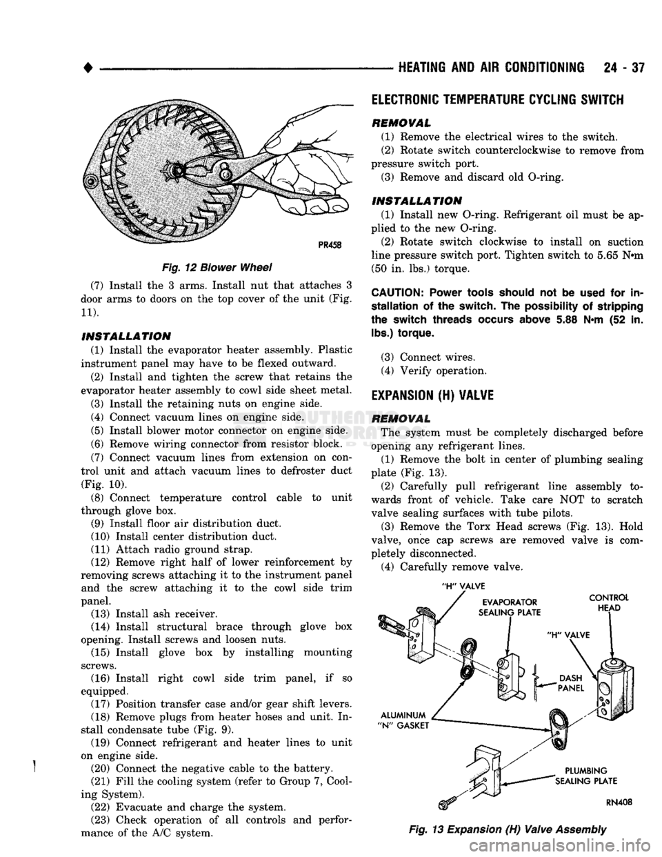
opening any refrigerant lines. (1) Remove the bolt in center of plumbing sealing
plate (Fig. 13).
(2) Carefully pull refrigerant line assembly to
wards front of vehicle. Take care NOT to scratch valve sealing surfaces with tube pilots.
(3) Remove the Torx Head screws (Fig. 13). Hold
valve, once cap screws are removed valve is com
pletely disconnected.
(4) Carefully remove valve.
Page 1475 of 1502
24
- 38
HEATING
AND AIR
CONDITIONING
INSTALLATION
(1) Remove and replace the aluminum N-gaskets
(1 on evaporator plate and 1 on plumbing plate). (2) Remove sealing cap from H-valve control head
side sealing surface and hold it against evaporator
sealing plate. DO NOT scratch sealing surface. In
stall the Torx Drive screws and tighten to 11 N-m (100 in. lbs.) torque.
(3) Remove sealing cap from plumbing side sealing
surface and hold plumbing up to valve. Install the
bolt and tighten to 23 N*m (200 in. lbs.) torque.
(4) Connect wires to electronic temperature cycling
switch. (5) After expansion valve is installed and system
charged and leak checked, repeat performance check.
AIR CONDITIONER DISTRIBUTION AND SPOT
COOLER
DUCTS-CENTER
REMOVAL (1) Disconnect the negative cable from the battery.
(2) Open glove box past stops.
(3) Remove right upper air duct by removing
mounting screw and pulling duct out through glove
box opening (Fig. 9).
(4) Remove instrument panel center brace.
(5) Remove right kick pad.
(6) Remove right instrument panel pivot bolt.
(7) Remove instrument panel cluster.
(8) Disconnect shift indicator cable.
(9) Lower steering column.
(10) Remove steering column studs.
(11) Remove radio.
(12) Remove mounting screws and remove scoop
connecting heater unit to center distribution duct. (13) Remove mounting screws and remove center
distribution duct by pulling bottom of instrument
panel out and dropping duct out (Fig. 9).
INSTALLATION
(1) Position the center distribution duct through
the bottom of instrument panel (Fig. 9). Install mounting screws.
(2) Position the scoop connecting heater unit to
center distribution duct. Install mounting screws.
(3) Install radio.
(4) Install steering column studs.
(5) Place steering column into position.
(6) Connect shift indicator cable.
(7) Install instrument panel cluster.
(8) Install right instrument panel pivot bolt.
(9) Install right kick pad.
(10) Install instrument panel center brace.
(11) Position the duct in through glove box open
ing (Fig. 9). Install mounting screw. (12) Close glove box.
(13) Connect the negative cable to the battery.
AIR CONDITIONER DISTRIBUTION AND SPOT
COOLER
DUCTS-RIGHT BI-LEVEL
REMOVAL (1) Disconnect the negative cable from the battery. (2) Open glove box past stops.
(3) Remove right upper air duct by removing
mounting screw and pulling duct out through glove
box opening (Fig. 9).
INSTALLATION
(1) Position the right upper air duct through glove
box opening (Fig. 9). Install mounting screw.
(2) Close glove box.
(3) Connect the negative cable to the battery.
AIR CONDITIONER DISTRIBUTION AND SPOT
COOLER
DUCTS-LEFT BI-LEVEL
REMOVAL
(1) Disconnect the negative cable from the battery.
(2) Remove instrument panel cluster.
(3) Disconnect shift indicator cable.
(4) Remove heater control.
(5) Remove mounting screws and cover that re
tains instrument panel wiring and let wiring hang
free.
(6) Remove mounting screw and slide left air duct
out through instrument cluster opening (Fig. 9).
INSTALLATION
(1) Slide left air duct in through instrument clus
ter opening (Fig. 9). Install mounting screw. (2) Position the cover that retains instrument
panel wiring. Install mounting screws.
(3) Install heater control.
(4) Connect shift indicator cable.
(5) Install instrument panel cluster.
(6) Connect the negative cable to the battery.
AIR OUTLET
ASSEMBLIES
RIGHT
SIDE
Both right side outlets are held in place with
spring loaded retaining clips.
REMOVAL (1) With outlet facing out and louver vanes open,
grasp adjusting vane with fingers.
(2) Pull smoothly and firmly to unseat clips and
complete removal toward rear of vehicle.
INSTALLATION
(1) Position outlet assembly in panel opening, f
making sure lettering stamped TOP is up (ribs on
housing match notches on instrument panel).
(2) Press housing assembly until both retaining
clips lock into place.