1993 DODGE TRUCK cycling switch
[x] Cancel search: cycling switchPage 586 of 1502
![DODGE TRUCK 1993 Service Repair Manual
WIRING
DIAGRAMS
8W
-
111
AIR CONDITIONING
COMPRESSOR
(RIGHT
SIDE
FORWARD
OF
ENGINE)
i
C26
14BR-
A21
14DB-
C3
i4DB/BK-ffi£^]QLJ
I86K
18BK
(LEFT
OF
COMPRESSOR)
Zl
DODGE TRUCK 1993 Service Repair Manual
WIRING
DIAGRAMS
8W
-
111
AIR CONDITIONING
COMPRESSOR
(RIGHT
SIDE
FORWARD
OF
ENGINE)
i
C26
14BR-
A21
14DB-
C3
i4DB/BK-ffi£^]QLJ
I86K
18BK
(LEFT
OF
COMPRESSOR)
Zl](/manual-img/12/56922/w960_56922-585.png)
WIRING
DIAGRAMS
8W
-
111
AIR CONDITIONING
COMPRESSOR
(RIGHT
SIDE
FORWARD
OF
ENGINE)
i
C26
14BR-
A21
14DB-
C3
i4DB/BK-ffi£^]QLJ
I86K
18BK
(LEFT
OF
COMPRESSOR)
Zl
18BK (RIGHT FENDER
SIDE
SHIELD) C13 20DB/0R-
TO FUSIBLE
„
LINK
$-
(SEE
SH 6) \ TO
POWERTRAIN
\
CONTROL MODULE
II
\
CAVITY
27,34
\ (SEE SH 26)
r
T
C20
18BR BI-DIRECTIONAL
ZENER
DIODE WIDE OPEN
THROTTLE CUTOUT
RELAY
(LEFT
FENDER
SIDE
SHIELD) C13 14DB/BK
Zl
14BK
TO
SPLICE
(SEE
SH 23)
C21
18DB/0R
TO
SPLICE
(SEE
SH 23)
SPLICE
(SEE
SH 21)
A/C
LOW
PRESSURE
SWITCH (RIGHT FENDER
SIDE
SHIELD)
A21
14DB
PROBE
(RIGHT
SIDE
SHIELD)
A/C
CYCLING SWITCH C2 18DB/0R-
A21
14DB-
C20 18BR-
C20 18BR-
J938W-H
A/C
AND
HEATER-
DIESEL
ENGINES
AD
70
Page 600 of 1502
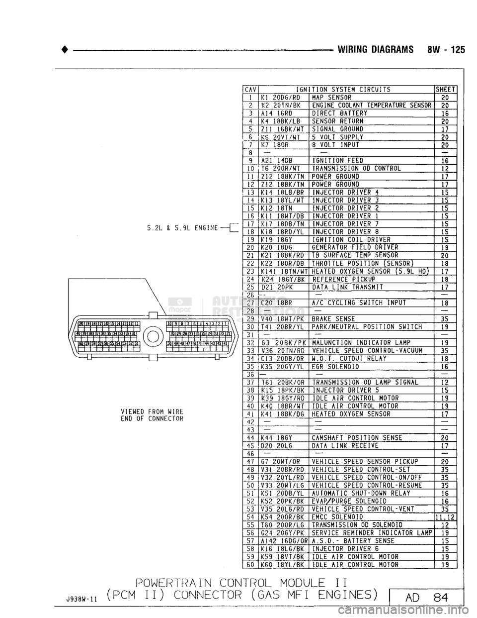
WIRING
DIAGRAMS 8W - 125
5.2L £ 5.9L ENGINE VIEWED FROM WIRE
END OF CONNECTOR
POWERTRAIN
CON
J938W-H
(PCM II) CONNECTOR
CAV
IGNITION
SYSTEM CIRCUITS SHEET
1
Kl
200G/RD
MAP
SENSOR
20
2"-1 K2
20TN/BK
ENGINE COOLANT TEMPERATURE SENSOR
20
3 A14
IBRD
DIRECT BATTERY
16
4 K4 18BK/LB
SENSOR
RETURN
20
5 Zll
16BK/WT
SIGNAL
GROUND
17
6 K6
20VT/WT
5 VOLT SUPPLY
20
7
K7
180R 8 VOLT INPUT
20
8 —
—
9 A21 14DB IGNITION FEED
16
10 T6
200R/WT
TRANSMISSION
OD CONTROL
12
11 Z12 18BK/TN POWER GROUND
17
12 Z12 18BK/TN POWER GROUND
17
13 |Kl4 18LB/BR
INJECTOR DRIVER 4
15
14 K13
18YL/WT
INJECTOR DRIVER 3
15
15 K12 18TN INJECTOR DRIVER 2
15
16
17" Kl1
18WT/DB
INJECTOR DRIVER 1
15
16
17"
K17
18DB/TN
INJECTOR DRIVER 7
15
18 K18
18RD/YL
INJECTOR DRIVER 8
15
19 K19 18GY IGNITION COIL DRIVER
15
20 K20 18DG GENERATOR FIELD DRIVER
19
21 K21
18BK/RD
TB SURFACE TEMP SENSOR
20
22 K22
180R/DB
THROTTLE POSITION (SENSOR)
18
23 K141
18TN/WT
HEATED OXYGEN SENSOR (5.9L HD)
17
24 K24 18GY/BK
REFERENCE
PICKUP
18
25 021
20PK
DATA LINK TRANSMIT
17
26 —
—
27 C20 18BR
A/C
CYCLING SWITCH INPUT
18
28 — _
29 V40
18WT/PK
BRAKE
SENSE
35
30 T41
20BR/YL
PARK/NEUTRAL POSITION SWITCH
19
31 —
—
32 G3
20BK/PK
MALUNCTION INDICATOR LAMP
19
33 V36
20TM/RD
VEHICLE SPEED CONTROL-VACUUM
35
34 C13 20DB/OR W.O.T. CUTOUT RELAY
18
35 K35 20GY/YL
EGR
SOLENOID
16
36 —
— —
37 TBI 20BK/0R
TRANSMISSION
OD LAMP SIGNAL
12
38 K15
18PK/BK
INJECTOR DRIVER 5
15
39
"40 K39 18GY/RD
IDLE AIR CONTROL MOTOR
19
39
"40 K40 18BR/WT IDLE AIR CONTROL MOTOR
19
41 K41
18BK/DG
HEATED OXYGEN SENSOR
17
42
43 —
—
42
43 —
—
—
44 K44 18GY CAMSHAFT POSITION
SENSE
20
45 020 20LG
DATA LINK RECEIVE
17
46 —
— —
47 G7
20WT/OR
VEHICLE SPEED SENSOR PICKUP
20
48 V31
20BR/RD
VEHICLE SPEED CONTROL-SET
35
49 V32
20YL/RD
VEHICLE SPEED CONTROL-ON/OFF
35
50 Y33
20WT/LG
VEHICLE SPEED CONTROL-RESUME
35
51 K51 20DB/YL AUTOMATIC SHUT-DOWN RELAY
16
52 K52
20PK/BK
EVAP/PURGE
SOLENOID
16
53 V35
20LG/RD
VEHICLE SPEED CONTROL-VENT
35
54 K54
200R/BK
EMCC
SOLENOID
11.12
55 T60
200R/LG
TRANSMISSION
OD SOLENOID
12
5G G24
20GY/PK
SERVICE
REMINDER INDICATOR LAMP
13
57 A142 16DG/0R
A.S.D.-
BATTERY
SENSE
15
58 K16 18LG/BK INJECTOR DRIVER 6
15
59 K59 18VT/BK IDLE AIR CONTROL MOTOR
19
60 K60 18YL/BK IDLE AIR CONTROL MOTOR
19
TROL
MODULE II
(GAS
MFI ENGINES) AD 84
Page 879 of 1502
14 - SO
FUEL
SYSTEM
•
HIGH
AND LOW
LIMITS
The powertrain control module (PCM) compares in
put signal voltages from each input device. It will es
tablish high and low limits that are programmed into it for that device. If the input voltage is not
within specifications and other diagnostic trouble code (DTC) criteria are met, a DTC will be stored in
memory. Other DTC criteria might include engine
rpm limits or input voltages from other sensors or switches. The other inputs might have to be sensed
by the PCM when it senses a high or low input volt age from the control system device in question.
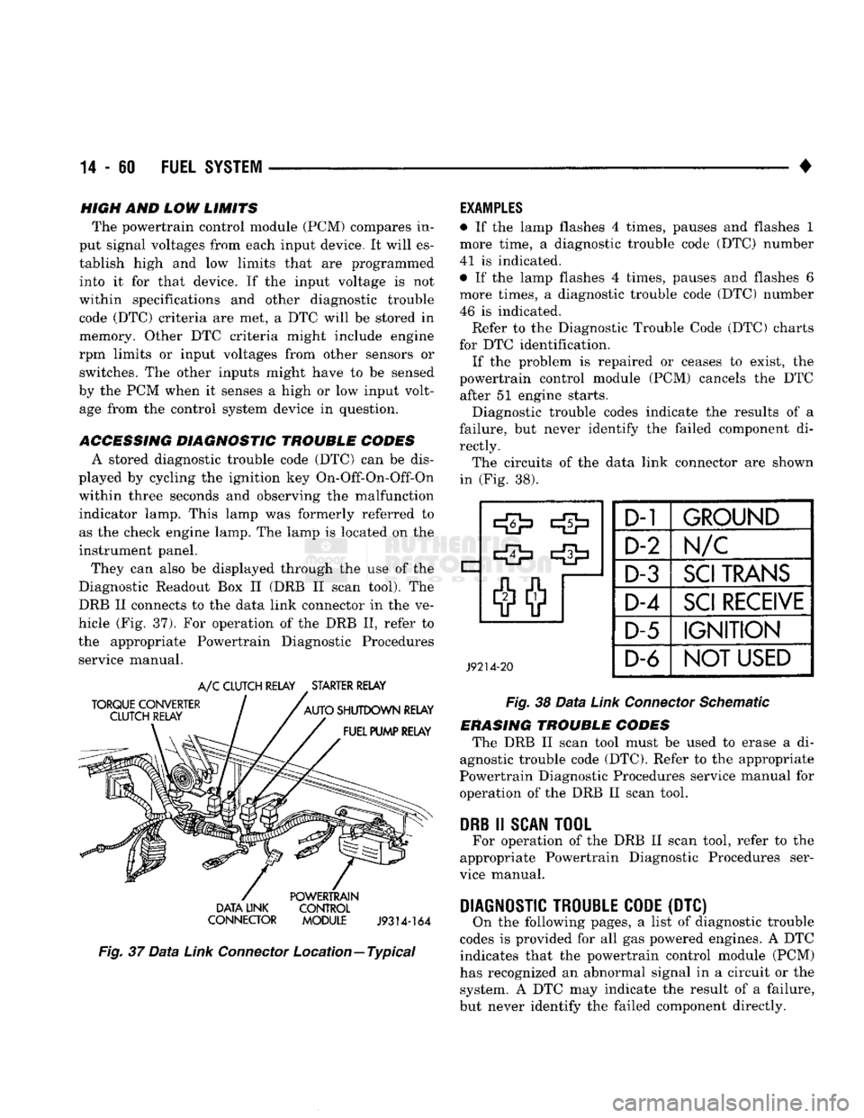
ACCESSING DIAGNOSTIC TROUBLE CODES A stored diagnostic trouble code (DTC) can be dis
played by cycling the ignition key On-Off-On-Off-On
within three seconds and observing the malfunction indicator lamp. This lamp was formerly referred to
as the check engine lamp. The lamp is located on the
instrument panel.
They can also be displayed through the use of the
Diagnostic Readout Box II (DRB II scan tool). The
DRB II connects to the data link connector in the ve
hicle (Fig. 37). For operation of the DRB II, refer to
the appropriate Powertrain Diagnostic Procedures service manual.
TORQUE CONVERTER
CLUTCH RELAY
A/C
CLUTCH RELAY
.
STARTER RELAY
AUTO
SHUTDOWN RELAY FUEL PUMP RELAY POWERTRAIN
DATA LINK CONTROL
CONNECTOR MODULE
J9314-164
Fig.
37
Data
Link
Connector
Location—Typical
EXAMPLES
• If the lamp flashes 4 times, pauses and flashes 1
more time, a diagnostic trouble code (DTC) number
41 is indicated.
• If the lamp flashes 4 times, pauses and flashes 6
more times, a diagnostic trouble code (DTC) number
46 is indicated. Refer to the Diagnostic Trouble Code (DTC) charts
for DTC identification. If the problem is repaired or ceases to exist, the
powertrain control module (PCM) cancels the DTC after 51 engine starts.
Diagnostic trouble codes indicate the results of a
failure, but never identify the failed component di
rectly. The circuits of the data link connector are shown
in (Fig. 38).
J9214-20
D-1
GROUND
D-2 Im/c
D-3
SCI
TRANS
D-4
SCI
RECEIVE
D-5
IGNITION
D-6
NOT
USED
Fig.
38
Data
Link
Connector
Schematic
ERASING TROUBLE CODES The DRB II scan tool must be used to erase a di
agnostic trouble code (DTC). Refer to the appropriate
Powertrain Diagnostic Procedures service manual for operation of the DRB II scan tool.
DRB
II
SCAN
TOOL
For operation of the DRB II scan tool, refer to the
appropriate Powertrain Diagnostic Procedures ser
vice manual.
DIAGNOSTIC TROUBLE CODE
(DTC) On the following pages, a list of diagnostic trouble
codes is provided for all gas powered engines. A DTC indicates that the powertrain control module (PCM)
has recognized an abnormal signal in a circuit or the system. A DTC may indicate the result of a failure,
but never identify the failed component directly.
Page 1438 of 1502
•
• —• •
HEATING
AND AIR
CONDITIONING
24 - 1 CONTENTS
page
CLIMATE CONTROL SYSTEM
............. 21
REFRIGERANT SYSTEM SERWICE
COMPRESSOR
SERWICE
(SD-709)
......... 21
PROCEDURES
.............
DIAGNOSTIC PROCEDURES
3
TORQUE SPECIFICATIONS
GENERAL INFORMATION
1
page
. 17
. 31
GENERAL INFORMATION
HEATER SYSTEM
All models use a Blend-Air type heater. Outside air
enters the heater through the cowl opening and
passes through a plenum chamber to the heater core. Air intake openings must be kept free of snow, ice and other obstructions for the heater system to pick
up sufficient outside air. A temperature control door
in the heater housing directs incoming air through
the heater core and/or the heater core bypass. The amount of blend (heated and non-heated air) is deter
mined by the setting of the temperature lever on the
instrument panel. Direction of the blended air is con
trolled by the HEAT-DEFROST lever on the instru ment panel. The blower switch and resistor block controls the
speed of the blower motor. This in turn controls the
velocity of the air flow from the heater outlets. The resistor block consists of 2 helical wound wire
resistors connected to terminals which are mechani cally attached to a glass-filled phenolic board. This
assembly is bolted to the plenum. The blower switch controls the blower motor speed
by selectively connecting the resistors in series to the
blower motor.
A self-adjusting clip, on each of 2 control cables has
been incorporated to simplify cable adjustment. This clip snaps onto the control cable core wire and will slide along the wire under a specific load to provide
an automatic cable adjustment.
AIR
CONDITIONING
SYSTEM
Air intake openings must be kept free of snow, ice
and other obstructions for the air conditioning sys
tem to pick up sufficient outside air.
COMPONENTS
• COMPRESSOR-The seven piston SD-709 com
pressor is used on all vehicles. This compressor com
presses the low pressure refrigerant vapor into a high pressure, high temperature vapor. • CLUTCH PULLEY AND COIL-These are
mounted on the compressor, providing a convenient
way to drive it and disengage it in accordance to the cooling needs.
• CONDENSER-The condenser is located in front
of the radiator. Its function is to cool the hot, high
pressure refrigerant gas causing it to condense into
high pressure liquid refrigerant.
• FILTER-DRIER—The filter-drier is used to remove
any traces of moisture from the refrigerant system.
This component incorporates the sight glass and the
high pressure relief valve.
• SIGHT GLASS-The sight glass is provided as a
diagnostic tool to observe refrigerant flow and indi cate refrigerant level. It is located at the top of the
filter drier.
• HIGH -PRESSURE RELIEF VALVE-This is a safety device designed to open automatically if the
system pressure reaches a predetermined level. This
will prevent system component damage. • EXPANSION (H) VALVE-The expansion (H)
valve is used to meter refrigerant into the evaporator
in accordance with cooling requirements. • EVAPORATOR COIL-The evaporator coil is lo
cated in the A/C unit. Its function is to cool and de-
humidify the air before it enters the vehicle. • FREEZE CONTROL-The main function of freeze
control is to prevent water on the evaporator coil face
from freezing which restricts the airflow. An elec
tronic temperature cycling switch is located on the
refrigerant plumbing (suction line) near the H-Valve.
The switch turns the compressor ON-OFF depending
on the temperature in the suction line. The switch is a sealed, specially calibrated unit. If found defective,
the switch must be replaced. • REFRIGERANT LINES-These lines are needed
to carry the refrigerant between the various system components.
• CONDENSATE DRAIN TUBE-Condensation
which accumulates on the bottom of the evaporator
HEATING
AND AIR
CONDITIONING
Page 1444 of 1502
•
HEATING AND AIR CONDITIONING 24 - 7 AIR CONDITIONING SYSTEM
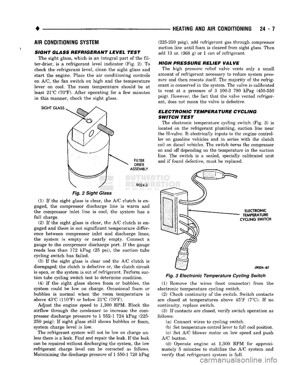
SIGHT GLASS REFRIGERANT LEWEL TEST The sight glass, which is an integral part of the fil
ter-drier, is a refrigerant level indicator (Fig. 2). To check the refrigerant level, clean the sight glass and
start the engine. Place the air conditioning controls
on A/C, the fan switch on high and the temperature lever on cool. The room temperature should be at
least 21°C (70°F). After operating for a few minutes
in this manner, check the sight glass.
SIGHT
GLASS
FILTER
DRIER
ASSEMBLY
9024-3
Fig.
2 Sight Glass
(1) If the sight glass is clear, the A/C clutch is en
gaged, the compressor discharge line is warm and
the compressor inlet line is cool; the system has a
full charge.
(2) If the sight glass is clear, the A/C clutch is en
gaged and there is not significant temperature differ
ence between compressor inlet and discharge lines;
the system is empty or nearly empty. Connect a gauge to the compressor discharge port. If the gauge
reads less than 172 kPag (25 psi), the suction tube cycling switch has failed.
(3) If the sight glass is clear and the A/C clutch is
disengaged; the clutch is defective or, the clutch circuit
is open, or the system is out of refrigerant. Perform suc
tion tube cycling switch test to determine condition.
(4) If the sight glass shows foam or bubbles, the
system could be low on charge. Occasional foam or
bubbles is normal when the room temperature is above 43°C (110°F) or below 21°C (70°F).
Adjust the engine speed to 1,300 RPM. Block the
airflow through the condenser to increase the com
pressor discharge pressure to 1 552-1 724 kPag (225- 250 psig). If sight glass still shows bubbles or foam,
system charge level is low. The refrigerant system will not be low on charge un
less there is a leak. Find and repair the leak. If the leak
can be repaired without discharging the system, the low
refrigerant charge level can be corrected as follows.
Maintaining the discharge pressure of 1 550-1 720 kPag (225-250 psig), add refrigerant gas through compressor
suction line until foam is cleared from sight glass. Then
add 13 oz. (368 g) or 1 can of refrigerant.
HIGH PRESSURE RELIEF
WALWE
The high pressure relief valve vents only a small
amount of refrigerant necessary to reduce system pres
sure and then reseats
itself.
The majority of the refrig
erant is conserved in the system. The valve is calibrated
to vent at a pressure of 3 100-3 790 kPag (450-550
psig).
However, the fact that the valve vented refriger ant, does not mean the valve is defective.
ELECTRONIC TEMPERATURE CYCLING
SWITCH TEST The electronic temperature cycling switch (Fig. 3) is
located on the refrigerant plumbing, suction line near
the H-valve. It electrically inputs to the engine control ler on gasoline vehicles and in series with the clutch
coil on diesel vehicles. The switch turns the compressor
on and off depending on the temperature in the suction
line.
The switch is a sealed, specially calibrated unit and if found defective, must be replaced.
ELECTRONIC
TEMPERATURE
CYCLING
SWITCH
J9324-97
Fig.
3 Electronic
Temperature
Cycling
Switch
(1) Remove the wires (boot connector) from the
electronic temperature cycling switch. (2) Check continuity of the switch. Switch contacts
are closed at temperatures above 45°F (7°C). If no
continuity, replace switch.
(3) If contacts are closed, verify switch operation as
follows:
(a) Connect wires to cycling switch.
(b) Set temperature control lever to full cool position. (c) Set A/C blower motor on low speed and push
A/C button.
(d) Operate engine at 1,300 RPM for approxi
mately 5 minutes to stabilize the A/C system and
verify that refrigerant system is full.
Page 1445 of 1502
24 - 8
HEATING
AND AIR
CONDITIONING
• (e) If compressor clutch cycles 3 to 10 times per
minute with temperature between 20°C-32°C (68°F-
90°F),
the cycling switch is normal. If the compressor
clutch fails to engage, check for continuity in the elec
trical circuit. Above 32°C (90°F) the compressor clutch
may be continuously engaged (non-cycling) due to the
high heat load. This condition is normal.
(4)
Refer to the Evaporator Heater Assembly for
the Removal/Installation procedures.
TESTING
THE
SYSTEM
FOR
LEAKS
If the air conditioning system is not cooling properly,
check that the refrigerant system is fully charged with
R-12.
Follow the procedures in the Sight Glass Refrig
erant Level Test section of this group.
If the refrigerant system is empty or low in refrig
erant charge, a leak at any of the line fittings or
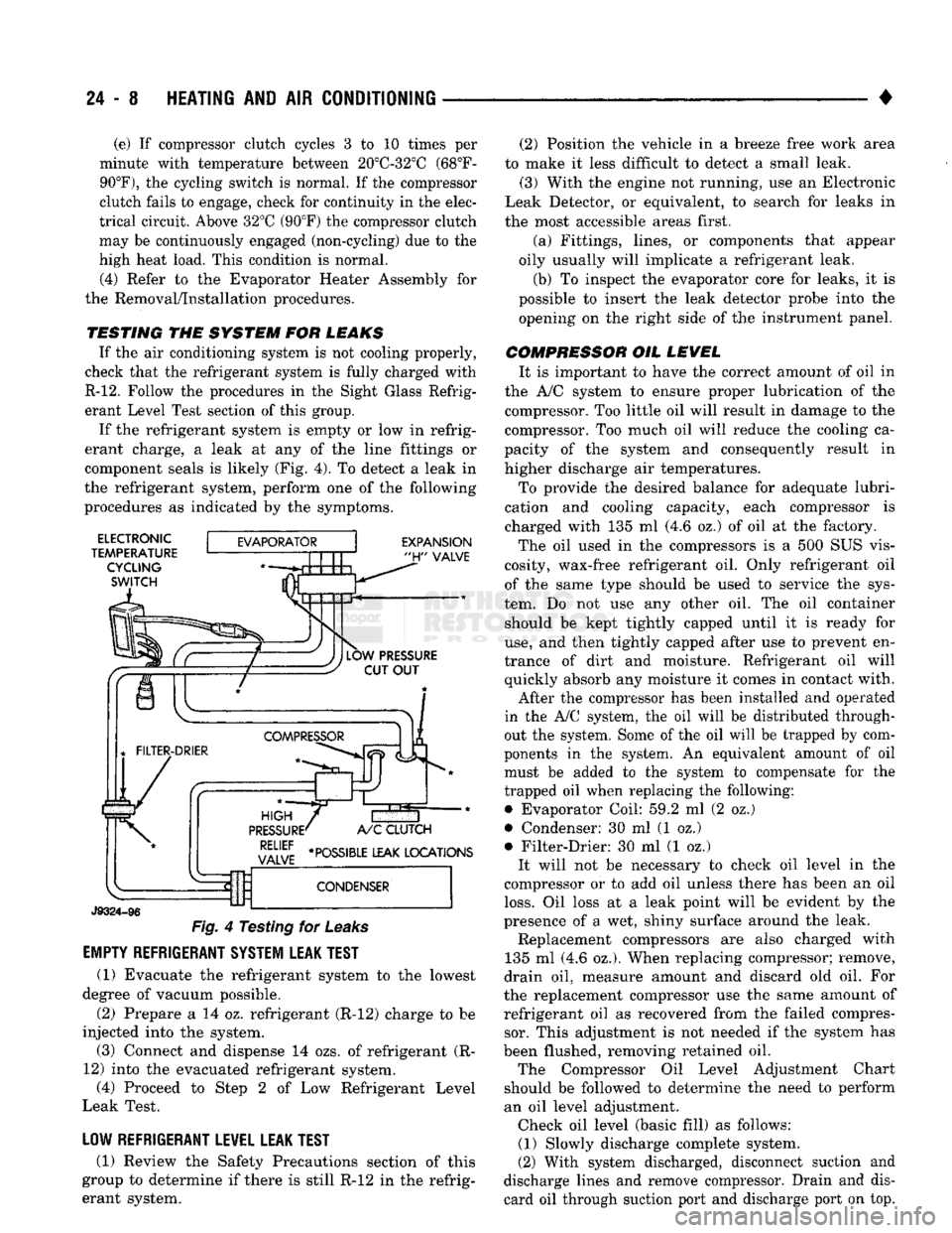
component seals is likely (Fig. 4). To detect a leak in
the refrigerant system, perform one of the following
procedures as indicated by the symptoms.
ELECTRONIC
TEMPERATURE CYCLING
SWITCH
EXPANSION
"H"
VALVE
J9324-96
Fig.
4 Testing for
Leaks
EMPTY REFRIGERANT SYSTEM LEAK TEST
(1) Evacuate the refrigerant system to the lowest
degree of vacuum possible.
(2) Prepare a 14 oz. refrigerant (R-12) charge to be
injected into the system. (3) Connect and dispense 14 ozs. of refrigerant (R-
12) into the evacuated refrigerant system, (4) Proceed to Step 2 of Low Refrigerant Level
Leak Test.
LOW REFRIGERANT LEVEL LEAK TEST
(1) Review the Safety Precautions section of this
group to determine if there is still R-12 in the refrig
erant system. (2) Position the vehicle in a breeze free work area
to make it less difficult to detect a small leak. (3) With the engine not running, use an Electronic
Leak Detector, or equivalent, to search for leaks in
the most accessible areas first.
(a) Fittings, lines, or components that appear
oily usually will implicate a refrigerant leak.
(b) To inspect the evaporator core for leaks, it is
possible to insert the leak detector probe into the opening on the right side of the instrument panel.
COMPRESSOR OIL LEVEL It is important to have the correct amount of oil in
the A/C system to ensure proper lubrication of the compressor. Too little oil will result in damage to the
compressor. Too much oil will reduce the cooling ca
pacity of the system and consequently result in
higher discharge air temperatures.
To provide the desired balance for adequate lubri
cation and cooling capacity, each compressor is
charged with 135 ml (4.6 oz.) of oil at the factory.
The oil used in the compressors is a 500 SUS vis
cosity, wax-free refrigerant oil. Only refrigerant oil of the same type should be used to service the sys
tem. Do not use any other oil. The oil container should be kept tightly capped until it is ready for
use,
and then tightly capped after use to prevent en
trance of dirt and moisture. Refrigerant oil will quickly absorb any moisture it comes in contact with.
After the compressor has been installed and operated
in the A/C system, the oil will be distributed through
out the system. Some of the oil will be trapped by com
ponents in the system. An equivalent amount of oil
must be added to the system to compensate for the
trapped oil when replacing the following: • Evaporator Coil: 59.2 ml (2 oz.)
• Condenser: 30 ml (1 oz.)
• Filter-Drier: 30 ml (1 oz.) It will not be necessary to check oil level in the
compressor or to add oil unless there has been an oil
loss.
Oil loss at a leak point will be evident by the
presence of a wet, shiny surface around the leak. Replacement compressors are also charged with
135 ml (4.6 oz.). When replacing compressor; remove,
drain oil, measure amount and discard old oil. For
the replacement compressor use the same amount of refrigerant oil as recovered from the failed compressor. This adjustment is not needed if the system has
been flushed, removing retained oil. The Compressor Oil Level Adjustment Chart
should be followed to determine the need to perform
an oil level adjustment. Check oil level (basic fill) as follows: (1) Slowly discharge complete system.
(2) With system discharged, disconnect suction and
discharge lines and remove compressor. Drain and dis card oil through suction port and discharge port on top.
Page 1448 of 1502
HEATING
AND
AIR
CONDITIONING
24 -
TEMPERATURE
IN
TEST AREA
21-29° C
(70-85°
F)
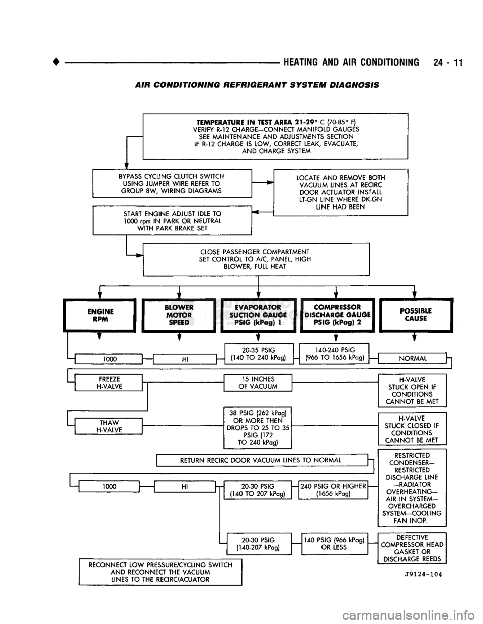
VERIFY R-12 CHARGE-CONNECT MANIFOLD GAUGES
SEE
MAINTENANCE AND ADJUSTMENTS SECTION
IF
R-12
CHARGE
IS
LOW, CORRECT LEAK, EVACUATE, AND CHARGE SYSTEM
BYPASS
CYCLING CLUTCH SWITCH USING JUMPER WIRE REFER
TO
GROUP
8W,
WIRING DIAGRAMS
START ENGINE ADJUST IDLE
TO 1000
rpm
IN
PARK OR NEUTRAL
WITH
PARK BRAKE SET LOCATE AND REMOVE BOTH
VACUUM LINES AT RECIRC DOOR ACTUATOR INSTALL
LT-GN LINE WHERE DK-GN LINE HAD BEEN
CLOSE
PASSENGER COMPARTMENT
SET
CONTROL TO A/C, PANEL, HIGH BLOWER, FULL HEAT
ENGINE
RPM BLOWER
MOTOR
SPEED
I
EVAPORATOR
I
SUCTION GAUGE
I
PSIG
(kPag)
1
COMPRESSOR
DISCHARGE
GAUGE
PSIG
(kPag)
2
—m
POSSIBLE
I
CAUSE
I
20-35
PSIG
140-240
PSIG
1000 —
HI
(140 TO 240
kPag)
(966
TO
1656
kPag)
i
— NORMAL
Cr a
FREEZE
H-VALVE 15 INCHES
OF VACUUM
THAW
H-VALVE 38 PSIG
(262
kPag)
OR MORE THEN
DROPS
TO 25 TO 35
PSIG
(172
TO
240
kPag)
RETURN RECIRC DOOR VACUUM LINES
TO
NORMAL a
1000
HI
20 30
PSIG
(140 TO 207
kPag)
H240
PSIG OR HIGHER
(1656
kPag)
20-30
PSIG
(140-207
kPag)
140
PSIG
(966
kPag)
OR
LESS
H-VALVE
STUCK OPEN
IF
CONDITIONS
CANNOT BE MET
H-VALVE
STUCK CLOSED
IF
CONDITIONS
CANNOT BE MET
RESTRICTED
CONDENSER-
RESTRICTED
DISCHARGE
LINE
-RADIATOR
OVERHEATING-
AIR
IN
SYSTEM- OVERCHARGED
SYSTEM-COOLING FAN INOP.
RECONNECT LOW PRESSURE/CYCLING SWITCH AND RECONNECT THE VACUUM LINES
TO
THE RECIRC/ACUATOR DEFECTIVE
COMPRESSOR
HEAD
GASKET
OR
DISCHARGE
REEDS
J9124-104
AIR
CONDITIONING REFRIGERANT SYSTEM DIAGNOSIS
Page 1449 of 1502
24-12
HEATING
AND AIR
CONDITIONING
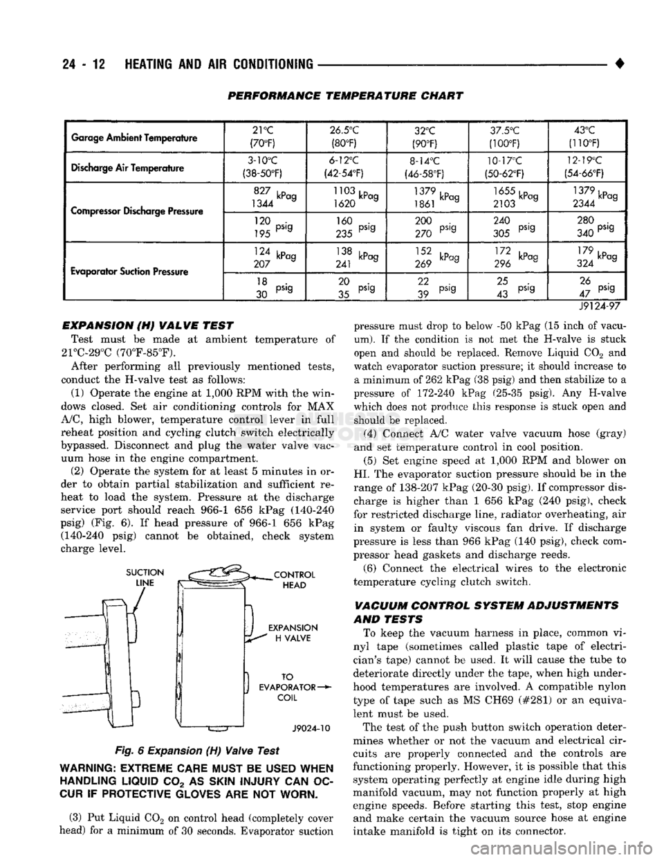
PERFORMANCE TEMPERATURE CHART
Garage
Ambient
Temperature
21
°C
(70°F) 26.5°C
(80°F) 32°C
(90°F) 3/.5°'J
(100T) 43°C
(110°F)
Discharge
Air Temperature
3-10°C
(38-50°F) 6-12°C
(42-54'F) 8-14°C
(46-58°F) 10-17°C
(50-62°F) 12-19°C
(54-66°F)
Compressor
Discharge Pressure
1344 a
1620 a
1861 kPag 2103 a 1379kPcg
2344 a
Compressor
Discharge Pressure
120 •
195 PS'9 160 .
235 PS'9 200 .
270 PS'9 240 .
305 PS'9 280 .
340 PS'9
Evaporator
Suction Pressure
124 kPag
207 a 138 kPag
241 J 269 kPag III kP°9
296 179 ,D
324 kPag
Evaporator
Suction Pressure
18 .
30 PS'9 20 .
35 pS'g 22
39 pS,g
25 .
43 pS'g 26 .
47 pS'9
J9124-97 pressure must drop to below -50 kPag (15 inch of vacu
um).
If the condition is not met the H-valve is stuck
open and should be replaced. Remove Liquid C02 and
watch evaporator suction pressure; it should increase to a minimum of 262 kPag (38 psig) and then stabilize to a
pressure of 172-240 kPag (25-35 psig). Any H-valve
which does not produce this response is stuck open and should be replaced.
(4) Connect A/C water valve vacuum hose (gray)
and set temperature control in cool position.
(5) Set engine speed at 1,000 RPM and blower on
HI.
The evaporator suction pressure should be in the
range of 138-207 kPag (20-30 psig). If compressor dis charge is higher than 1 656 kPag (240 psig), check
for restricted discharge line, radiator overheating, air in system or faulty viscous fan drive. If discharge
pressure is less than 966 kPag (140 psig), check com
pressor head gaskets and discharge reeds.
(6) Connect the electrical wires to the electronic
temperature cycling clutch switch.
VACUUM CONTROL SYSTEM ADJUSTMENTS
AND TESTS To keep the vacuum harness in place, common vi
nyl tape (sometimes called plastic tape of electri
cian's tape) cannot be used. It will cause the tube to
deteriorate directly under the tape, when high under
hood temperatures are involved. A compatible nylon type of tape such as MS CH69 (#281) or an equivalent must be used.
The test of the push button switch operation deter
mines whether or not the vacuum and electrical cir cuits are properly connected and the controls are
functioning properly. However, it is possible that this system operating perfectly at engine idle during high
manifold vacuum, may not function properly at high engine speeds. Before starting this test, stop engine and make certain the vacuum source hose at engine
intake manifold is tight on its connector.
EXPANSION (H) VALVE TEST
Test must be made at ambient temperature of
21°C-29°C (70°F-85°F).
After performing all previously mentioned tests,
conduct the H-valve test as follows:
(1) Operate the engine at 1,000 RPM with the win
dows closed. Set air conditioning controls for MAX
A/C,
high blower, temperature control lever in full
reheat position and cycling clutch switch electrically
bypassed. Disconnect and plug the water valve vac uum hose in the engine compartment. (2) Operate the system for at least 5 minutes in or
der to obtain partial stabilization and sufficient re
heat to load the system. Pressure at the discharge service port should reach 966-1 656 kPag (140-240
psig) (Fig. 6). If head pressure of 966-1 656 kPag (140-240 psig) cannot be obtained, check system
charge level.
Fig.
6
Expansion
(H)
Valve
Test
WARNING:
EXTREME
CARE
MUST
BE
USED
WHEN
HANDLING
LIQUID
C02 AS
SKIN
INJURY
CAN OC
CUR
IF
PROTECTIVE
GLOVES
ARE NOT
WORN.
(3) Put Liquid C02 on control head (completely cover
head) for a minimum of 30 seconds. Evaporator suction