1993 CHEVROLET PLYMOUTH ACCLAIM belt
[x] Cancel search: beltPage 1589 of 2438
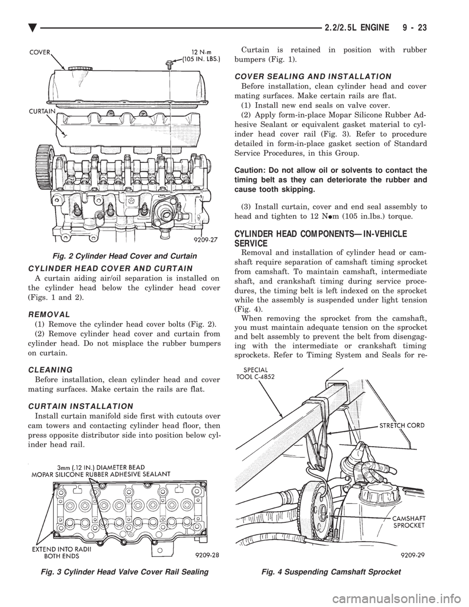
CYLINDER HEAD COVER AND CURTAIN
A curtain aiding air/oil separation is installed on
the cylinder head below the cylinder head cover
(Figs. 1 and 2).
REMOVAL
(1) Remove the cylinder head cover bolts (Fig. 2).
(2) Remove cylinder head cover and curtain from
cylinder head. Do not misplace the rubber bumpers
on curtain.
CLEANING
Before installation, clean cylinder head and cover
mating surfaces. Make certain the rails are flat.
CURTAIN INSTALLATION
Install curtain manifold side first with cutouts over
cam towers and contacting cylinder head floor, then
press opposite distributor side into position below cyl-
inder head rail. Curtain is retained in position with rubber
bumpers (Fig. 1).
COVER SEALING AND INSTALLATION
Before installation, clean cylinder head and cover
mating surfaces. Make certain rails are flat. (1) Install new end seals on valve cover.
(2) Apply form-in-place Mopar Silicone Rubber Ad-
hesive Sealant or equivalent gasket material to cyl-
inder head cover rail (Fig. 3). Refer to procedure
detailed in form-in-place gasket section of Standard
Service Procedures, in this Group.
Caution: Do not allow oil or solvents to contact the
timing belt as they can deteriorate the rubber and
cause tooth skipping.
(3) Install curtain, cover and end seal assembly to
head and tighten to 12 N Im (105 in.lbs.) torque.
CYLINDER HEAD COMPONENTSÐIN-VEHICLE
SERVICE
Removal and installation of cylinder head or cam-
shaft require separation of camshaft timing sprocket
from camshaft. To maintain camshaft, intermediate
shaft, and crankshaft timing during service proce-
dures, the timing belt is left indexed on the sprocket
while the assembly is suspended under light tension
(Fig. 4). When removing the sprocket from the camshaft,
you must maintain adequate tension on the sprocket
and belt assembly to prevent the belt from disengag-
ing with the intermediate or crankshaft timing
sprockets. Refer to Timing System and Seals for re-Fig. 2 Cylinder Head Cover and Curtain
Fig. 3 Cylinder Head Valve Cover Rail SealingFig. 4 Suspending Camshaft Sprocket
Ä 2.2/2.5L ENGINE 9 - 23
Page 1590 of 2438
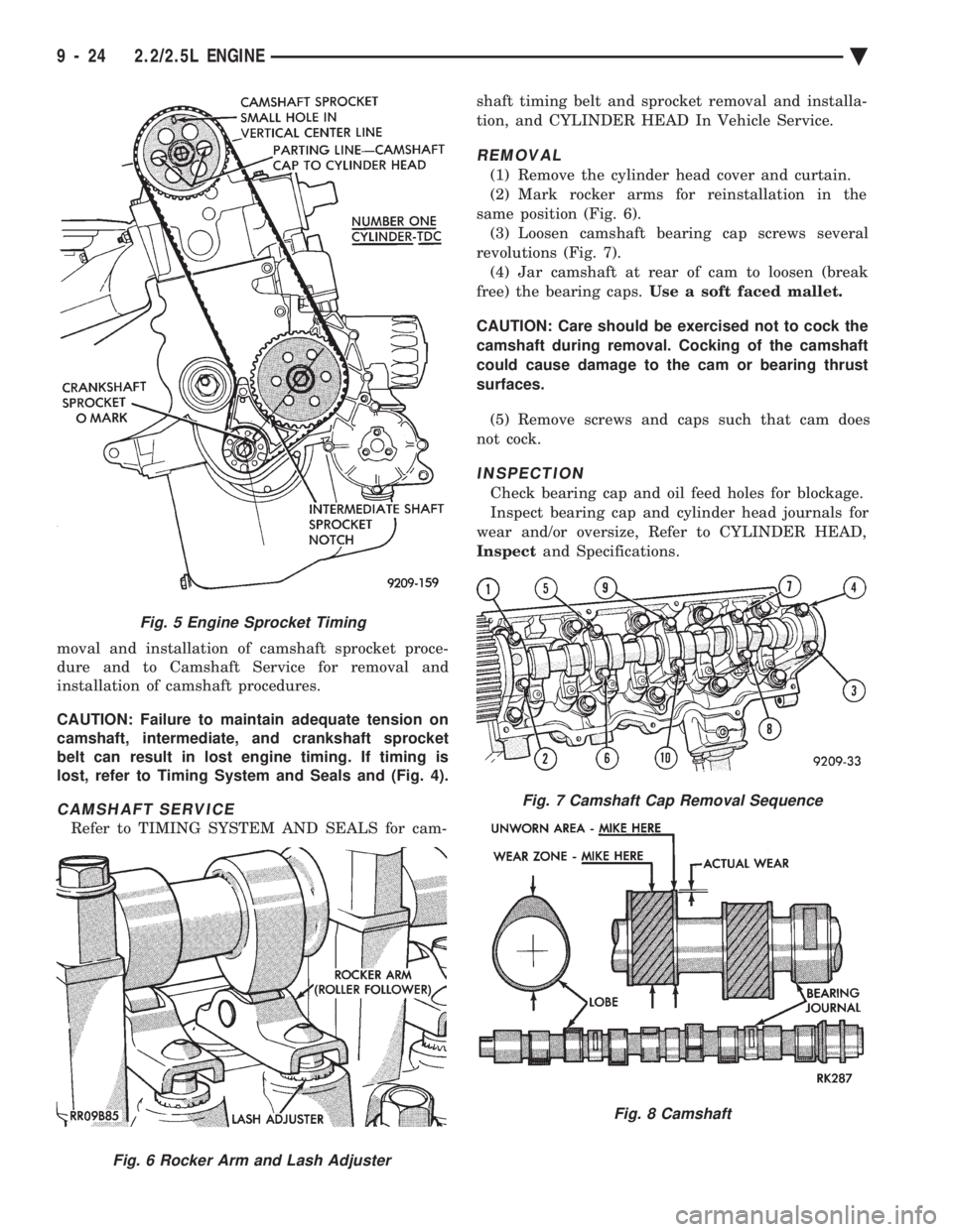
moval and installation of camshaft sprocket proce-
dure and to Camshaft Service for removal and
installation of camshaft procedures.
CAUTION: Failure to maintain adequate tension on
camshaft, intermediate, and crankshaft sprocket
belt can result in lost engine timing. If timing is
lost, refer to Timing System and Seals and (Fig. 4).
CAMSHAFT SERVICE
Refer to TIMING SYSTEM AND SEALS for cam- shaft timing belt and sprocket removal and installa-
tion, and CYLINDER HEAD In Vehicle Service.
REMOVAL
(1) Remove the cylinder head cover and curtain.
(2) Mark rocker arms for reinstallation in the
same position (Fig. 6). (3) Loosen camshaft bearing cap screws several
revolutions (Fig. 7). (4) Jar camshaft at rear of cam to loosen (break
free) the bearing caps. Use a soft faced mallet.
CAUTION: Care should be exercised not to cock the
camshaft during removal. Cocking of the camshaft
could cause damage to the cam or bearing thrust
surfaces.
(5) Remove screws and caps such that cam does
not cock.
INSPECTION
Check bearing cap and oil feed holes for blockage.
Inspect bearing cap and cylinder head journals for
wear and/or oversize, Refer to CYLINDER HEAD,
Inspect and Specifications.
Fig. 5 Engine Sprocket Timing
Fig. 6 Rocker Arm and Lash Adjuster
Fig. 7 Camshaft Cap Removal Sequence
Fig. 8 Camshaft
9 - 24 2.2/2.5L ENGINE Ä
Page 1591 of 2438
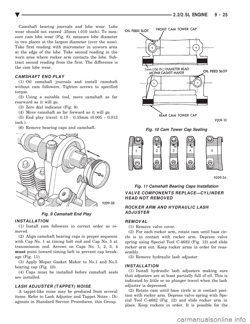
Camshaft bearing journals and lobe wear. Lobe
wear should not exceed .25mm (.010 inch). To mea-
sure cam lobe wear (Fig. 8), measure lobe diameter
in two places at the largest diameter (over the nose).
Take first reading with micrometer in unworn area
at the edge of the lobe. Take second reading in the
worn area where rocker arm contacts the lobe. Sub-
tract second reading from the first. The difference is
the cam lobe wear.
CAMSHAFT END PLAY
(1) Oil camshaft journals and install camshaft
without cam followers. Tighten screws to specified
torque. (2) Using a suitable tool, move camshaft as far
rearward as it will go. (3) Zero dial indicator (Fig. 9).
(4) Move camshaft as far forward as it will go.
(5) End play travel: 0.13 - 0.33mm (0.005 - 0.013
inch.). (6) Remove bearing caps and camshaft.
INSTALLATION
(1) Install cam followers in correct order as re-
moved. (2) Align camshaft bearing caps in proper sequence
with Cap No. 1 at timing belt end and Cap No. 5 at
transmission end. Arrows on Caps No. 1, 2, 3, 4
must point toward timing belt to prevent cap break-
age (Fig. 11). (3) Apply Mopar Gasket Maker to No.1 and No.5
bearing cap (Fig. 10). (4) Caps must be installed before camshaft seals
are installed.
LASH ADJUSTER (TAPPET) NOISE
A tappet-like noise may be produced from several
items. Refer to Lash Adjuster and Tappet Noise - Di-
agnosis in Standard Service Procedures, this Group.
VALVE COMPONENTS REPLACEÐCYLINDER HEAD NOT REMOVED
ROCKER ARM AND HYDRAULIC LASH ADJUSTER
REMOVAL
(1) Remove valve cover.
(2) For each rocker arm, rotate cam until base cir-
cle is in contact with rocker arm. Depress valve
spring using Special Tool C-4682 (Fig. 12) and slide
rocker arm out. Keep rocker arms in order for reas-
sembly. (3) Remove hydraulic lash adjuster.
INSTALLATION
(1) Install hydraulic lash adjusters making sure
that adjusters are at least partially full of oil. This is
indicated by little or no plunger travel when the lash
adjuster is depressed. (2) Rotate cam until base circle is in contact posi-
tion with rocker arm. Depress valve spring with Spe-
cial Tool C-4682 (Fig. 12) and slide rocker arm in
place. Keep rockers in order. It is possible for the
Fig. 9 Camshaft End Play
Fig. 10 Cam Tower Cap Sealing
Fig. 11 Camshaft Bearing Caps Installation
Ä 2.2/2.5L ENGINE 9 - 25
Page 1592 of 2438
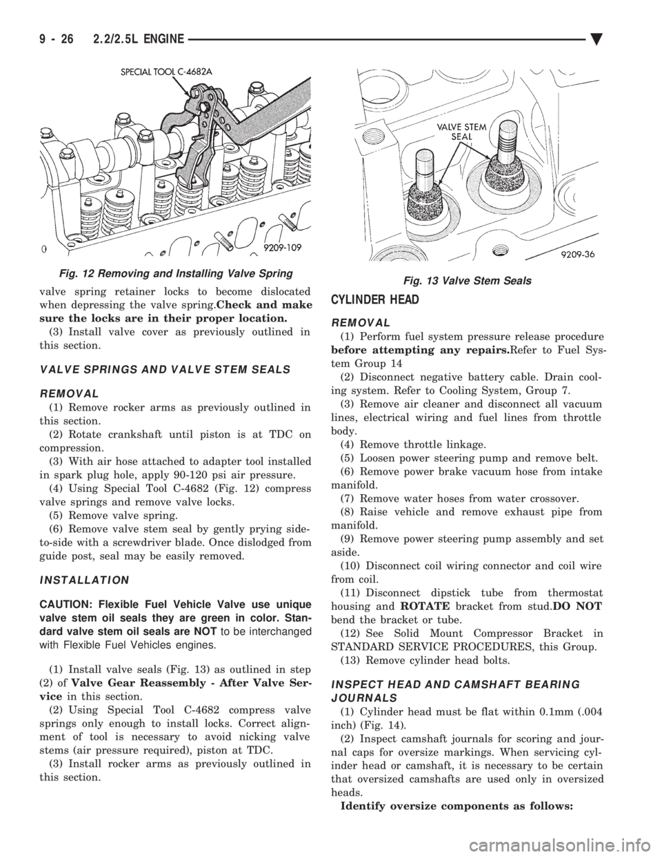
valve spring retainer locks to become dislocated
when depressing the valve spring. Check and make
sure the locks are in their proper location. (3) Install valve cover as previously outlined in
this section.
VALVE SPRINGS AND VALVE STEM SEALS
REMOVAL
(1) Remove rocker arms as previously outlined in
this section. (2) Rotate crankshaft until piston is at TDC on
compression. (3) With air hose attached to adapter tool installed
in spark plug hole, apply 90-120 psi air pressure. (4) Using Special Tool C-4682 (Fig. 12) compress
valve springs and remove valve locks. (5) Remove valve spring.
(6) Remove valve stem seal by gently prying side-
to-side with a screwdriver blade. Once dislodged from
guide post, seal may be easily removed.
INSTALLATION
CAUTION: Flexible Fuel Vehicle Valve use unique
valve stem oil seals they are green in color. Stan-
dard valve stem oil seals are NOT to be interchanged
with Flexible Fuel Vehicles engines.
(1) Install valve seals (Fig. 13) as outlined in step
(2) of Valve Gear Reassembly - After Valve Ser-
vice in this section.
(2) Using Special Tool C-4682 compress valve
springs only enough to install locks. Correct align-
ment of tool is necessary to avoid nicking valve
stems (air pressure required), piston at TDC. (3) Install rocker arms as previously outlined in
this section.
CYLINDER HEAD
REMOVAL
(1) Perform fuel system pressure release procedure
before attempting any repairs. Refer to Fuel Sys-
tem Group 14 (2) Disconnect negative battery cable. Drain cool-
ing system. Refer to Cooling System, Group 7. (3) Remove air cleaner and disconnect all vacuum
lines, electrical wiring and fuel lines from throttle
body. (4) Remove throttle linkage.
(5) Loosen power steering pump and remove belt.
(6) Remove power brake vacuum hose from intake
manifold. (7) Remove water hoses from water crossover.
(8) Raise vehicle and remove exhaust pipe from
manifold. (9) Remove power steering pump assembly and set
aside. (10) Disconnect coil wiring connector and coil wire
from coil. (11) Disconnect dipstick tube from thermostat
housing and ROTATEbracket from stud. DO NOT
bend the bracket or tube. (12) See Solid Mount Compressor Bracket in
STANDARD SERVICE PROCEDURES, this Group. (13) Remove cylinder head bolts.
INSPECT HEAD AND CAMSHAFT BEARINGJOURNALS
(1) Cylinder head must be flat within 0.1mm (.004
inch) (Fig. 14). (2) Inspect camshaft journals for scoring and jour-
nal caps for oversize markings. When servicing cyl-
inder head or camshaft, it is necessary to be certain
that oversized camshafts are used only in oversized
heads. Identify oversize components as follows:
Fig. 12 Removing and Installing Valve SpringFig. 13 Valve Stem Seals
9 - 26 2.2/2.5L ENGINE Ä
Page 1597 of 2438
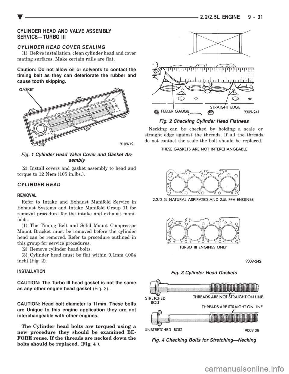
CYLINDER HEAD AND VALVE ASSEMBLY
SERVICEÐTURBO III
CYLINDER HEAD COVER SEALING
(1) Before installation, clean cylinder head and cover
mating surfaces. Make certain rails are flat.
Caution: Do not allow oil or solvents to contact the
timing belt as they can deteriorate the rubber and
cause tooth skipping.
(2) Install covers and gasket assembly to head and
torque to 12 N Im (105 in.lbs.).
CYLINDER HEAD
REMOVAL
Refer to Intake and Exhaust Manifold Service in
Exhaust Systems and Intake Manifold Group 11 for
removal procedure for the intake and exhaust mani-
folds. (1) The Timing Belt and Solid Mount Compressor
Mount Bracket must be removed before the cylinder
head can be removed. Refer to procedure outlined in
this group for service procedures. (2) Remove cylinder head bolts.
(3) Cylinder head must be flat within 0.1mm (.004
inch) (Fig. 2).
INSTALLATION
CAUTION: The Turbo III head gasket is not the same
as any other engine head gasket (Fig. 3).
CAUTION: Head bolt diameter is 11mm. These bolts
are Unique to this engine application they are not
interchangeable with other engines.
The Cylinder head bolts are torqued using a
new procedure they should be examined BE-
FORE reuse. If the threads are necked down the
bolts should be replaced. (Fig. 4 ). Necking can be checked by holding a scale or
straight edge against the threads. If all the threads
do not contact the scale the bolt should be replaced.
Fig. 2 Checking Cylinder Head Flatness
Fig. 3 Cylinder Head Gaskets
Fig. 4 Checking Bolts for StretchingÐNecking
Fig. 1 Cylinder Head Valve Cover and Gasket As- sembly
Ä 2.2/2.5L ENGINE 9 - 31
Page 1598 of 2438
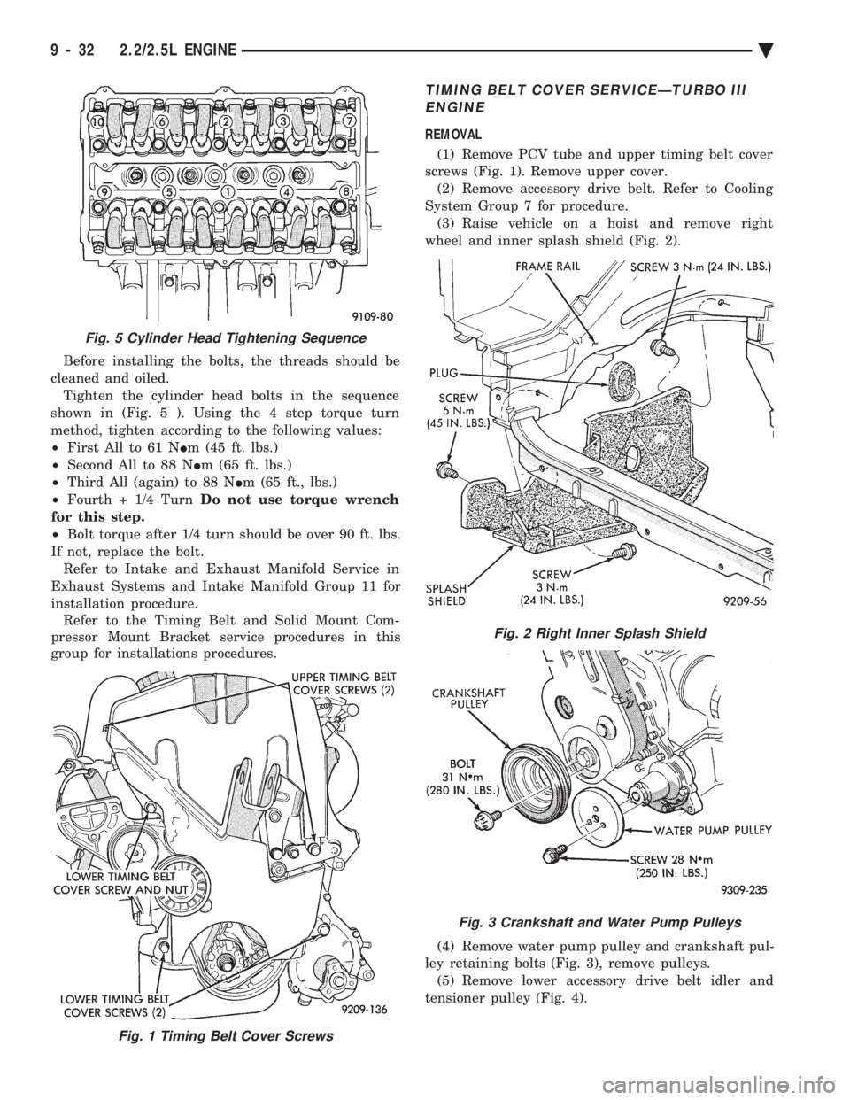
Before installing the bolts, the threads should be
cleaned and oiled. Tighten the cylinder head bolts in the sequence
shown in (Fig. 5 ). Using the 4 step torque turn
method, tighten according to the following values:
² First All to 61 N Im (45 ft. lbs.)
² Second All to 88 N Im (65 ft. lbs.)
² Third All (again) to 88 N Im (65 ft., lbs.)
² Fourth + 1/4 Turn Do not use torque wrench
for this step.
² Bolt torque after 1/4 turn should be over 90 ft. lbs.
If not, replace the bolt. Refer to Intake and Exhaust Manifold Service in
Exhaust Systems and Intake Manifold Group 11 for
installation procedure. Refer to the Timing Belt and Solid Mount Com-
pressor Mount Bracket service procedures in this
group for installations procedures.
TIMING BELT COVER SERVICEÐTURBO III
ENGINE
REMOVAL
(1) Remove PCV tube and upper timing belt cover
screws (Fig. 1). Remove upper cover. (2) Remove accessory drive belt. Refer to Cooling
System Group 7 for procedure. (3) Raise vehicle on a hoist and remove right
wheel and inner splash shield (Fig. 2).
(4) Remove water pump pulley and crankshaft pul-
ley retaining bolts (Fig. 3), remove pulleys. (5) Remove lower accessory drive belt idler and
tensioner pulley (Fig. 4).
Fig. 1 Timing Belt Cover Screws
Fig. 5 Cylinder Head Tightening Sequence
Fig. 2 Right Inner Splash Shield
Fig. 3 Crankshaft and Water Pump Pulleys
9 - 32 2.2/2.5L ENGINE Ä
Page 1599 of 2438
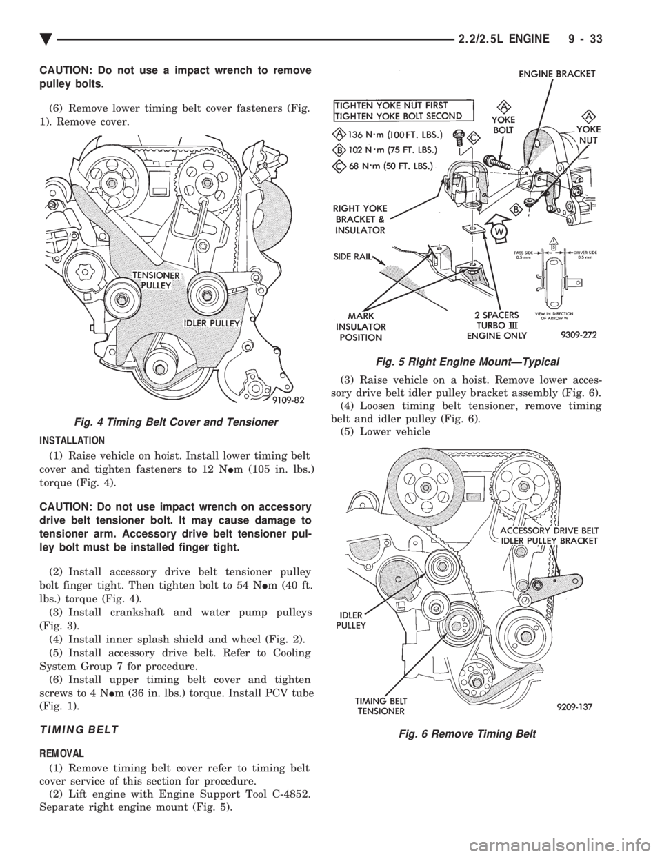
CAUTION: Do not use a impact wrench to remove
pulley bolts. (6) Remove lower timing belt cover fasteners (Fig.
1). Remove cover.
INSTALLATION (1) Raise vehicle on hoist. Install lower timing belt
cover and tighten fasteners to 12 N Im (105 in. lbs.)
torque (Fig. 4).
CAUTION: Do not use impact wrench on accessory
drive belt tensioner bolt. It may cause damage to
tensioner arm. Accessory drive belt tensioner pul-
ley bolt must be installed finger tight. (2) Install accessory drive belt tensioner pulley
bolt finger tight. Then tighten bolt to 54 N Im (40 ft.
lbs.) torque (Fig. 4). (3) Install crankshaft and water pump pulleys
(Fig. 3). (4) Install inner splash shield and wheel (Fig. 2).
(5) Install accessory drive belt. Refer to Cooling
System Group 7 for procedure. (6) Install upper timing belt cover and tighten
screws to 4 N Im (36 in. lbs.) torque. Install PCV tube
(Fig. 1).
TIMING BELT
REMOVAL
(1) Remove timing belt cover refer to timing belt
cover service of this section for procedure. (2) Lift engine with Engine Support Tool C-4852.
Separate right engine mount (Fig. 5). (3) Raise vehicle on a hoist. Remove lower acces-
sory drive belt idler pulley bracket assembly (Fig. 6). (4) Loosen timing belt tensioner, remove timing
belt and idler pulley (Fig. 6). (5) Lower vehicle
Fig. 4 Timing Belt Cover and Tensioner
Fig. 5 Right Engine MountÐTypical
Fig. 6 Remove Timing Belt
Ä 2.2/2.5L ENGINE 9 - 33
Page 1600 of 2438
CAMSHAFT AND CRANKSHAFT TIMING
PROCEDURE
INSTALLATION
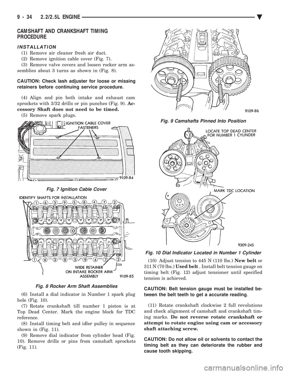
(1) Remove air cleaner fresh air duct.
(2) Remove ignition cable cover (Fig. 7).
(3) Remove valve covers and loosen rocker arm as-
semblies about 3 turns as shown in (Fig. 8).
CAUTION: Check lash adjuster for loose or missing
retainers before continuing service procedure.
(4) Align and pin both intake and exhaust cam
sprockets with 3/32 drills or pin punches (Fig. 9). Ac-
cessory Shaft does not need to be timed. (5) Remove spark plugs.
(6) Install a dial indicator in Number 1 spark plug
hole (Fig. 10). (7) Rotate crankshaft till number 1 piston is at
Top Dead Center. Mark the engine block for TDC
reference. (8) Install timing belt and idler pulley in sequence
shown in (Fig. 11). (9) Remove dial indicator from cylinder head (Fig.
10). Remove drills or pins from camshaft sprockets
(Fig. 11). (10) Adjust tension to 445 N (110 lbs.)
New beltor
311 N (70 lbs.) Used belt. Install belt tension gauge on
timing belt (Fig. 12) adjust tensioner until specified
tension is achieved.
CAUTION: Belt tension gauge must be installed be-
tween the belt teeth to get a accurate reading .
(11) Rotate crankshaft clockwise 2 full revolutions
and check alignment of camshaft and crankshaft tim-
ing marks. Do not reverse rotate crankshaft or
attempt to rotate engine using cam or accessory
shaft attaching screw.
CAUTION: Do not allow oil or solvents to contact the
timing belt as they can deteriorate the rubber and
cause tooth skipping.
Fig. 7 Ignition Cable Cover
Fig. 8 Rocker Arm Shaft Assemblies
Fig. 9 Camshafts Pinned Into Position
Fig. 10 Dial Indicator Located in Number 1 Cylinder
9 - 34 2.2/2.5L ENGINE Ä