1993 CHEVROLET PLYMOUTH ACCLAIM belt
[x] Cancel search: beltPage 2301 of 2438
(3) Separate buckle/belt assembly from vehicle.
INBOARD BUCKLE/CENTER OCCUPANT BELT INSTALLATION
Reverse the preceding operation.
FRONT SEATS
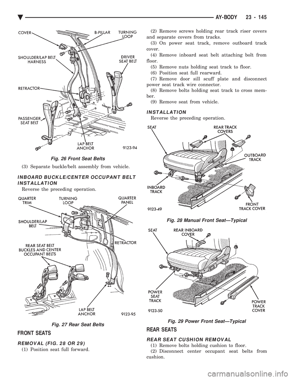
REMOVAL (FIG. 28 OR 29)
(1) Position seat full forward. (2) Remove screws holding rear track riser covers
and separate covers from tracks. (3) On power seat track, remove outboard track
cover. (4) Remove inboard seat belt attaching bolt from
floor. (5) Remove nuts holding seat track to floor.
(6) Position seat full rearward.
(7) Remove door sill scuff plate and disconnect
power seat track wire connector. (8) Remove bolts holding seat track to cross mem-
ber. (9) Remove seat from vehicle.
INSTALLATION
Reverse the preceding operation.
REAR SEATS
REAR SEAT CUSHION REMOVAL
(1) Remove bolts holding cushion to floor.
(2) Disconnect center occupant seat belts from
cushion.
Fig. 26 Front Seat Belts
Fig. 27 Rear Seat Belts
Fig. 28 Manual Front SeatÐTypical
Fig. 29 Power Front SeatÐTypical
Ä AY-BODY 23 - 145
Page 2310 of 2438
HEATER AND A/C PERFORMANCE TESTS
HEATER OUTPUT TEST
PRE-DIAGNOSTIC PREPARATIONS
Review Safety Precautions and Warnings before
performing the following procedures. Check the radiator coolant level, drive belt tension,
and engine vacuum line connections. Also check ra-
diator air flow and radiator fan operation. Start en-
gine and allow to warm up to normal operating
temperature.
WARNING: DO NOT REMOVE RADIATOR CAP
WHEN ENGINE IS HOT, PERSONAL INJURY CAN
RESULT.
If vehicle has been run recently, wait 15 minutes
before removing cap. Place a rag over the cap and
turn it to the first safety stop. Allow pressure to es-
cape through the overflow tube. When the system
stabilizes, remove the cap completely.
MAXIMUM HEATER OUTPUT: TEST AND ACTION
Engine coolant is provided to the heater system by
two 16 mm (5/8 inch inside diameter) heater hoses.
With engine idling at normal running temperature,
set the control to maximum heat, floor, and high
blower setting. Using a test thermometer, check the
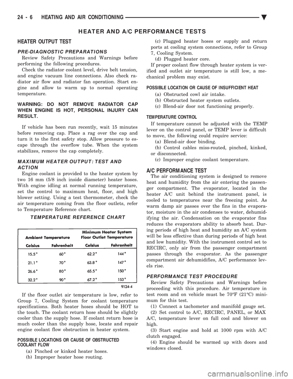
air temperature coming from the floor outlets, refer
to Temperature Reference chart.
If the floor outlet air temperature is low, refer to
Group 7, Cooling System for coolant temperature
specifications. Both heater hoses should be HOT to
the touch. The coolant return hose should be slightly
cooler than the supply hose. If coolant return hose is
much cooler than the supply hose, locate and repair
engine coolant flow obstruction in heater system.
POSSIBLE LOCATIONS OR CAUSE OF OBSTRUCTED
COOLANT FLOW
(a) Pinched or kinked heater hoses.
(b) Improper heater hose routing. (c) Plugged heater hoses or supply and return
ports at cooling system connections, refer to Group
7, Cooling System. (d) Plugged heater core.
If proper coolant flow through heater system is ver-
ified and outlet air temperature is still low, a me-
chanical problem may exist.
POSSIBLE LOCATION OR CAUSE OF INSUFFICIENT HEAT
(a) Obstructed cowl air intake.
(b) Obstructed heater system outlets.
(c) Blend-air door not functioning properly.
TEMPERATURE CONTROL If temperature cannot be adjusted with the TEMP
lever on the control panel, or TEMP lever is difficult
to move, the following could require service: (a) Blend-air door binding.
(b) Control cables miss-routed, pinched, kinked,
or disconnected. (c) Improper engine coolant temperature.A/C PERFORMANCE TEST
The air conditioning system is designed to remove
heat and humidity from the air entering the passen-
ger compartment. The evaporator, located in the
heater A/C unit behind the instrument panel, is
cooled to temperatures near the freezing point. As
warm damp air passes over the fins in the evapora-
tor, moisture in the air condenses to water, dehumid-
ifying the air. Condensation on the evaporator fins
reduces the evaporators ability to absorb heat. Dur-
ing periods of high heat and humidity an A/C system
will be less effective than during periods of high heat
and low humidity. With the instrument control set to
RECIRC, only air from the passenger compartment
passes through the evaporator. As the passenger
compartment air dehumidifies, A/C performance lev-
els rise.
PERFORMANCE TEST PROCEDURE
Review Safety Precautions and Warnings before
proceeding with this procedure. Air temperature in
test room and on vehicle must be 70ÉF (21ÉC) mini-
mum for this test. (1) Connect a tachometer and manifold gauge set.
(2) Set control to A/C, RECIRC, PANEL, or MAX
A/C, temperature lever on full cool and blower on
high. (3) Start engine and hold at 1000 rpm with A/C
clutch engaged. (4) Engine should be warmed up with doors and
windows closed.
TEMPERATURE REFERENCE CHART
24 - 6 HEATING AND AIR CONDITIONING Ä
Page 2317 of 2438
VARIABLE DISPLACEMENT COMPRESSORÐMODEL 6C17 INDEX
page page
Clutch Coil Tests ......................... 17
Compressor ............................. 17
Compressor Clutch Inoperative .............. 13
Compressor Clutch/Coil Assembly ............ 19
Compressor Diagnosis ..................... 13
Compressor Front Shaft Seal ............... 20 Compressor High Pressure Cut-Out Switch
..... 21
Compressor High Pressure Relief Valve (HPR) . . 22
Compressor Identification ................... 13
Compressor Main or Sub Control Valves ....... 22
Compressor Noise ........................ 13
General Information ....................... 13
GENERAL INFORMATION
The Variable Displacement Compressor (VDC) pro-
vides maximum A/C performance under most condi-
tions. It is designed to operate continuously without
any cycling of the compressor clutch. The compressor
has a variable angle wobble plate with six axially
oriented cylinders. During vehicle A/C system operation, the compres-
sor will change its displacement to match the vehi-
cles A/C cooling demands. When the A/C system
needs more cooling capacity, the compressor will in-
crease its pumping capacity. This is done by increas-
ing the wobble plate angle to increase the piston
stroke. When the A/C system cooling demand is low,
the compressor will decrease its pumping capacity by
reducing the piston pumping stroke. The low cooling
capacity will prevent evaporator from freezing.
COMPRESSOR IDENTIFICATION
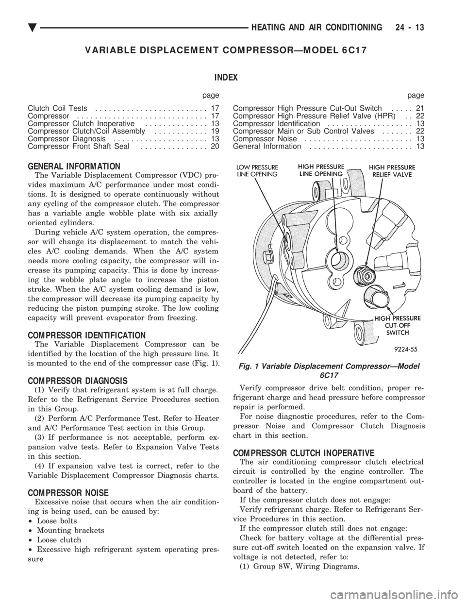
The Variable Displacement Compressor can be
identified by the location of the high pressure line. It
is mounted to the end of the compressor case (Fig. 1).
COMPRESSOR DIAGNOSIS
(1) Verify that refrigerant system is at full charge.
Refer to the Refrigerant Service Procedures section
in this Group. (2) Perform A/C Performance Test. Refer to Heater
and A/C Performance Test section in this Group. (3) If performance is not acceptable, perform ex-
pansion valve tests. Refer to Expansion Valve Tests
in this section. (4) If expansion valve test is correct, refer to the
Variable Displacement Compressor Diagnosis charts.
COMPRESSOR NOISE
Excessive noise that occurs when the air condition-
ing is being used, can be caused by:
² Loose bolts
² Mounting brackets
² Loose clutch
² Excessive high refrigerant system operating pres-
sure Verify compressor drive belt condition, proper re-
frigerant charge and head pressure before compressor
repair is performed. For noise diagnostic procedures, refer to the Com-
pressor Noise and Compressor Clutch Diagnosis
chart in this section.
COMPRESSOR CLUTCH INOPERATIVE
The air conditioning compressor clutch electrical
circuit is controlled by the engine controller. The
controller is located in the engine compartment out-
board of the battery. If the compressor clutch does not engage:
Verify refrigerant charge. Refer to Refrigerant Ser-
vice Procedures in this section. If the compressor clutch still does not engage:
Check for battery voltage at the differential pres-
sure cut-off switch located on the expansion valve. If
voltage is not detected, refer to: (1) Group 8W, Wiring Diagrams.
Fig. 1 Variable Displacement CompressorÐModel 6C17
Ä HEATING AND AIR CONDITIONING 24 - 13
Page 2321 of 2438
(2) The appropriate Powertrain Diagnostic Proce-
dures Manual for diagnostic information. (3) The Compressor Clutch DiagnosisÐVariable
Displacement Compressor chart in this section. (4) On 2.2 L Turbo III engines, check for battery
voltage at the Thermal Limiter Switch located on the
compressor. If voltage is found at the cut-off and/or thermal
limiter switch, reconnect switch. Then check for bat-
tery voltage between the compressor clutch connector
terminals. If voltage is detected, perform A/C Clutch Coil
Tests. Refer to Clutch Coil Tests in this section.
CLUTCH COIL TESTS
(1) Verify battery state of charge. (Test indicator
in battery should be green). (2) Connect an ammeter (0-10 ampere scale) in se-
ries with the clutch coil terminal. Use a volt meter
(0-20 volt scale) with clip leads measuring voltage
across the battery and A/C clutch. (3) With A/C control in A/C mode and blower at
low speed, start the engine and run at normal idle. (4) The A/C clutch should engage immediately and
the clutch voltage should be within two volts of the
battery voltage. If the A/C clutch does not engage,
test the fusible link. (5) The A/C clutch coil is acceptable if the current
draw is 2.0 to 3.7 amperes at 11.5-12.5 volts at clutch
coil. This is with the work area temperature at 21ÉC
(70ÉF). If voltage is more than 12.5 volts, add electri-
cal loads by turning on electrical accessories until
voltage reads below 12.5 volts. If coil current reads zero, the coil is open and
should be replaced. If the ammeter reading is 4 am-
peres or more, the coil is shorted and should be re-
placed. If the coil voltage is not within two volts of
the battery voltage, test clutch coil feed circuit for
excessive voltage drop.
COMPRESSOR
The A/C compressor may be removed and posi-
tioned without discharging the refrigerant system.
Discharging is not necessary if removing the A/C
compressor clutch/coil assembly, engine, cylinder
head, or generator.
WARNING: REFRIGERANT PRESSURES REMAIN HIGH
EVEN THOUGH THE ENGINE MAY BE TURNED OFF.
BEFORE REMOVING A FULLY CHARGED COMPRES-
SOR, REVIEW THE SAFETY PRECAUTIONS AND
WARNINGS SECTION IN THIS GROUP. DO NOT TWIST
OR KINK THE REFRIGERANT LINES WHEN REMOV-
ING A FULLY CHARGED COMPRESSOR. SAFETY
GLASSES MUST BE WORN.
REMOVAL AND INSTALLATION
(1) Disconnect NEGATIVE battery cable.
(2) Loosen and remove drive belts (Refer to Group
7, Cooling System) and disconnect compressor clutch
wire lead. (3) Remove refrigerant lines from compressor (if
necessary). (4) Remove compressor attaching nuts and bolts
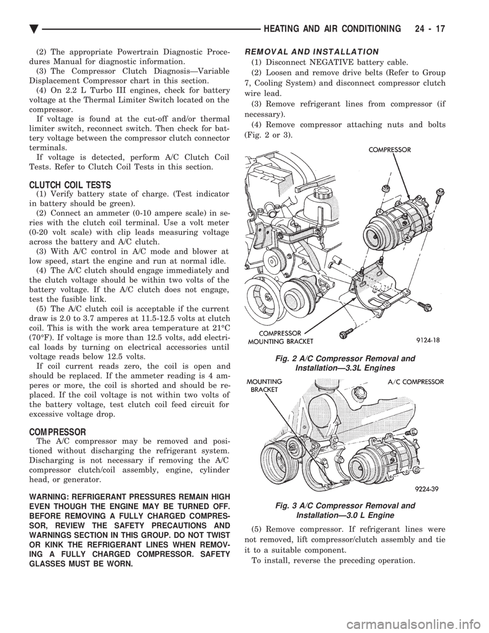
(Fig. 2 or 3).
(5) Remove compressor. If refrigerant lines were
not removed, lift compressor/clutch assembly and tie
it to a suitable component. To install, reverse the preceding operation.
Fig. 2 A/C Compressor Removal and InstallationÐ3.3L Engines
Fig. 3 A/C Compressor Removal and InstallationÐ3.0 L Engine
Ä HEATING AND AIR CONDITIONING 24 - 17
Page 2328 of 2438
FIXED DISPLACEMENT COMPRESSORÐMODEL 10PA17 INDEX
page page
Compressor ............................. 24
Compressor Clutch/Coil Assembly ............ 24
Compressor Front Shaft Seal ............... 27 Compressor High-Pressure Relief Valve
....... 30
Refrigerant System Diagnosis ............... 30
COMPRESSOR
COMPRESSOR NOISE
Excessive noise that occurs when the air condition-
ing is being used, can be caused by:
² Loose bolts
² Mounting brackets
² Loose clutch
² Excessive high refrigerant system operating pres-
sure Verify compressor drive belt condition, proper re-
frigerant charge and head pressure before compressor
repair is performed. For noise diagnostic procedures, refer to the Com-
pressor Noise and Compressor Clutch Diagnosis
chart in this section.
REMOVAL AND INSTALLATION
The A/C compressor may be removed and posi-
tioned without discharging the refrigerant system.
Discharging is not necessary if removing the A/C
compressor clutch/coil assembly, engine, cylinder
head, or generator.
WARNING: REFRIGERANT PRESSURES REMAIN
HIGH EVEN THOUGH THE ENGINE MAY BE
TURNED OFF. BEFORE REMOVING A FULLY
CHARGED COMPRESSOR, REVIEW THE SAFETY
PRECAUTIONS AND WARNINGS SECTION IN THIS
GROUP. DO NOT TWIST OR KINK THE REFRIGER-
ANT LINES WHEN REMOVING A FULLY CHARGED
COMPRESSOR. SAFETY GLASSES MUST BE
WORN.
(1) Disconnect Negative battery cable.
(2) Loosen and remove drive belts (refer to Group
7, Cooling System) and disconnect compressor clutch
wire lead. (3) Remove refrigerant lines from compressor (if
necessary). (4) Remove compressor attaching nuts and bolts.
(5) Remove compressor. If refrigerant lines were
not removed, lift compressor/clutch assembly and tie
it to a suitable component. To install, reverse the preceding operation. If nec-
essary, refer to Charging Refrigerant System in the
Refrigerant Service Procedures section.
COMPRESSOR CLUTCH/COIL ASSEMBLY
CLUTCH INOPERATIVE
The air conditioning compressor clutch electrical
circuit is controlled by the engine controller. The
controller is located in the engine compartment out-
board of the battery. If the compressor clutch does not engage:
Verify refrigerant charge.
If the compressor clutch still does not engage check
for battery voltage at the low pressure or differential
pressure cut-off switch located on the expansion
valve. If voltage is not detected, refer to:
² Group 8W, Wiring Diagrams.
² The appropriate Powertrain Diagnostic Procedures
Manual for diagnostic information. If voltage is detected at the cut-off switch, recon-
nect switch. Then check for battery voltage between
the compressor clutch connector terminals. If voltage is detected, perform A/C Clutch Coil
Tests.
CLUTCH COIL TESTS
(1) Verify battery state of charge. (Test indicator
in battery should be green). (2) Connect an ammeter (0-10 ampere scale) in se-
ries with the clutch coil terminal. Use a volt meter
(0-20 volt scale) with clip leads measuring voltage
across the battery and A/C clutch. (3) With A/C control in A/C mode and blower at
low speed, start the engine and run at normal idle. (4) The A/C clutch should engage immediately and
the clutch voltage should be within two volts of the
battery voltage. If the A/C clutch does not engage,
test the fusible link. (5) The A/C clutch coil is acceptable if the current
draw is 2.0 to 3.7 amperes at 11.5-12.5 volts at clutch
coil. This is with the work area temperature at 21ÉC
(70ÉF). If voltage is more than 12.5 volts, add electri-
cal loads by turning on electrical accessories until
voltage reads below 12.5 volts. If coil current reads zero, the coil is open and
should be replaced. If the ammeter reading is 4 am-
peres or more, the coil is shorted and should be re-
placed. If the coil voltage is not within two volts of
the battery voltage, test clutch coil feed circuit for
excessive voltage drop.
24 - 24 HEATING AND AIR CONDITIONING Ä
Page 2336 of 2438
FIXED DISPLACEMENT COMPRESSORÐMODEL TR105 INDEX
page page
Compressor ............................. 32
Compressor Clutch/Coil Assembly ............ 32
Compressor Shaft Bearing/Seal .............. 35 Refrigerant System Diagnosis
............... 36
Thermal Limiter Switch .................... 34
COMPRESSOR
Cleanliness is extremely important when disassem-
bly of the compressor is necessary. The surfaces
around the suction and discharge ports of the com-
pressor should be cleaned thoroughly before opening
the system at these points. If compressor is removed
from vehicle, apply tape to the opened ports to pre-
vent any contamination.
REMOVAL
(1) Disconnect battery negative cable.
(2) Loosen and remove drive belts (refer to Group
7, Cooling System). (3) Disconnect compressor clutch wire lead.
(4) Using a refrigerant recovery machine, remove
refrigerant from the A/C system. (5) Remove refrigerant lines from compressor.
(6) Remove compressor attaching bolts.
(7) Remove compressor.
INSTALLATION
(1) Position the compressor on the mount and fit
drive belt. (2) Tighten the compressor attaching bolts to 41
N Im (30 ft. lbs.) torque.
(3) Adjust drive belt (see Group 7, Cooling Sys-
tem). (4) Install refrigerant hoses.
(5) Connect the clutch wire.
(6) Evacuate and charge the system.
(7) Connect the battery negative cable.
COMPRESSOR CLUTCH/COIL ASSEMBLY
CLUTCH INOPERATIVE
The air conditioning compressor clutch electrical
circuit is controlled by the engine controller. The
controller is located in the engine compartment out-
board of the battery. If the compressor clutch does not engage:
Verify refrigerant charge.
If the compressor clutch still does not engage check
for battery voltage at the low pressure or differential
pressure cut-off switch located on the expansion
valve. If voltage is not detected, refer to:
² Group 8W, Wiring Diagrams.
² The appropriate Powertrain Diagnostic Procedures
Manual for diagnostic information. If voltage is detected at the cut-off switch, recon-
nect switch. Then check for battery voltage between
the compressor clutch connector terminals. If voltage is detected, perform A/C Clutch Coil
Tests.
CLUTCH COIL TESTS
(1) Verify battery state of charge. (Test indicator
in battery should be green). (2) Connect an ammeter (0-10 ampere scale) in se-
ries with the clutch coil terminal. Use a volt meter
(0-20 volt scale) with clip leads measuring voltage
across the battery and A/C clutch. (3) With A/C control in A/C mode and blower at
low speed, start the engine and run at normal idle. (4) The A/C clutch should engage immediately and
the clutch voltage should be within two volts of the
battery voltage. If the A/C clutch does not engage,
test the fusible link. (5) The A/C clutch coil is acceptable if the current
draw is 2.0 to 3.7 amperes at 11.5-12.5 volts at clutch
coil. This is with the work area temperature at 21ÉC
(70ÉF). If voltage is more than 12.5 volts, add electri-
cal loads by turning on electrical accessories until
voltage reads below 12.5 volts. If coil current reads zero, the coil is open and
should be replaced. If the ammeter reading is 4 am-
peres or more, the coil is shorted and should be re-
placed. If the coil voltage is not within two volts of
the battery voltage, test clutch coil feed circuit for
excessive voltage drop.
REMOVAL
(1) Remove the compressor from the mount.
(2) To prevent compressor shaft rotation, install 2
(6 mm) bolts, along with 2 wrenches, to the threaded
holes in the armature plate (Fig. 1). Remove com-
pressor shaft nut. (3) Tap the armature plate with a plastic and re-
move plate and shim(s).
CAUTION: Do not use screwdrivers between the ar-
mature plate assembly and rotor-pulley to remove
the armature plate. This may damage the armature
plate assembly.
24 - 32 HEATING AND AIR CONDITIONING Ä
Page 2342 of 2438
FIXED DISPLACEMENT COMPRESSORÐMODEL SD709P INDEX
page page
Compressor ............................. 38
Compressor Clutch/Coil Assembly ............ 38
Compressor Shaft Seal .................... 41 Cylinder Head/Valve Plate
.................. 44
Description ............................. 38
Refrigerant System Diagnosis ............... 45
DESCRIPTION
The Sanden compressor is a 7 piston design. Sys-
tem lubrication is provided by 135 ml 615 ml (4.6 oz.
6 0.5 oz.) of 500 viscosity refrigerant oil.
The clutch used on the compressor consists of 3 ba-
sic components:
² The pulley
² Front plate
² Field coil
The pulley and field coil are attached to the front
head of the compressor with tapered snap rings. The
hub is keyed to the compressor shaft and is retained
on the shaft with a self-locking nut. Special service
tools are required to remove and install the clutch
plate on the compressor shaft.
COMPRESSOR
The A/C compressor may be removed and posi-
tioned without discharging the refrigerant system.
Discharging is not necessary if removing the A/C
compressor clutch/coil assembly, engine, cylinder
head, or generator.
WARNING: REFRIGERANT PRESSURES REMAIN
HIGH EVEN THOUGH THE ENGINE MAY BE
TURNED OFF. BEFORE REMOVING A FULLY
CHARGED COMPRESSOR, REVIEW THE SAFETY
PRECAUTIONS AND WARNINGS SECTION IN THIS
GROUP. DO NOT TWIST OR KINK THE REFRIGER-
ANT LINES WHEN REMOVING A FULLY CHARGED
COMPRESSOR. SAFETY GLASSES MUST BE
WORN.
REMOVAL
(1) Disconnect negative cable from battery.
(2) Loosen and remove drive belts (refer to group
7, Cooling System) and disconnect compressor clutch
wire lead. (3) Remove refrigerant lines from compressor (if
necessary). (4) Remove compressor attaching nuts and bolts.
(5) Remove compressor. If refrigerant lines were
not removed, lift compressor/clutch assembly and tie
it to a suitable component. To install, reverse the removal procedure.
COMPRESSOR CLUTCH/COIL ASSEMBLY
The magnetic clutch consists of a stationary elec-
tro-magnetic coil and a rotating pulley and plate as-
sembly. The electromagnetic coil is retained on the com-
pressor with a snap ring and is dimpled to maintain
its position. The pulley and plate assembly are mounted on the
compressor shaft. When the compressor is not in operation, the pul-
ley free wheels on the clutch hub bearing. When the
coil is energized the plate is magnetically engaged
with the pulley and turns the compressor shaft.
REMOVAL
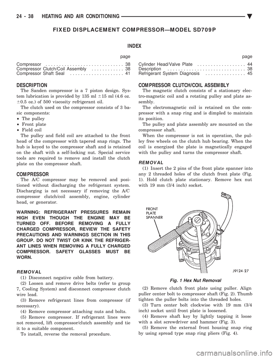
(1) Insert the 2 pins of the front plate spanner into
any 2 threaded holes of the clutch front plate (Fig.
1). Hold clutch plate stationary. Remove hex nut
with 19 mm (3/4 inch) socket.
(2) Remove clutch front plate using puller. Align
puller center bolt to compressor shaft (Fig. 2). Thumb
tighten the puller bolts into the threaded holes. (3) Turn center bolt clockwise with 19 mm (3/4
inch) socket until front plate is loosened. (4) Remove shaft key by lightly tapping it loose
with a slot screwdriver and hammer (Fig. 3). (5) Remove the external front housing snap ring
by using spread type snap ring pliers (Fig. 4).
Fig. 1 Hex Nut Removal
24 - 38 HEATING AND AIR CONDITIONING Ä
Page 2376 of 2438
NONÐCOMPUTER AIDED DIAGNOSTIC TESTS
Determine whether the operator complaint is due
to a system failure or improper operation of the ATC
system. The system will to go into a maximum heat
or cooling mode if the operator changes the tempera-
ture setting four or more degrees. Check the following:
² Coolant level
² Refrigerant charge
² Drive belt tension
² Radiator air flow
² Radiator fan operation
² Air suction of In-car Temperature Sensor/Aspirator
To check air suction of the Aspirator, place a small
piece of tissue paper over the Aspirator opening on
the instrument panel. This opening is located to the
right of the steering column. The tissue paper should
cling to the opening if system is functioning properly. Bring the engine to normal operating temperature
and proceed with Computer Aided Diagnostic Proce-
dures. Always test the entire system after each re-
pair has been performed.
COMPUTER AIDED DIAGNOSTIC TESTS
The ATC control has a computer capable of trou-
bleshooting the entire ATC system in approximately
60 seconds. The engine must be running and at nor-
mal operating temperature during the test to provide
hot coolant for the heater. During the ATC Diagnostic Test, the computer will
calibrate the Mode and Blend Door actuators.
CAUTION: Do not remove the actuators from the
heater-A/C unit assembly with power applied. Re-
moval should only be done with the Ignition OFF.
The actuators have no mechanical stops to limit the
travel. If the actuator rotates and is not connected
to the unit assembly, it will become un-calibrated.
The Diagnostic Test is capable of checking all elec-
trical signals between the ATC Control Module, ac-
tuators, sensors and blower control. The Diagnostic Test will display two types of Diag-
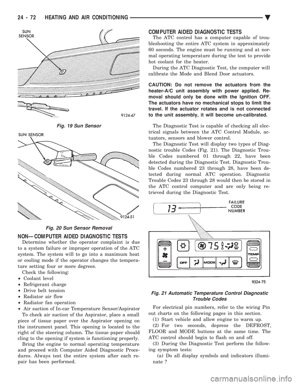
nostic trouble Codes (Fig. 21). The Diagnostic Trou-
ble Codes numbered 01 through 22, have been
detected during the Diagnostic Test. Diagnostic Trou-
ble Codes numbered 23 through 28, have been de-
tected during normal ATC operation. Diagnostic
Trouble Codes 23 through 28 would then be stored in
the ATC control computer and are only being re-
trieved during the Diagnostic Test.
For electrical pin numbers, refer to the wiring Pin
out charts on the following pages in this section. (1) Start vehicle and allow engine to warm up.
(2) For two seconds, depress the DEFROST,
FLOOR and MODE buttons at the same time. The
ATC control should begin to flash on and off. (3) During the Diagnostic Test perform the follow-
ing symptom tests: (a) Do all display symbols and indicators illumi-
nate ?
Fig. 19 Sun Sensor
Fig. 20 Sun Sensor Removal
Fig. 21 Automatic Temperature Control Diagnostic Trouble Codes
24 - 72 HEATING AND AIR CONDITIONING Ä