1993 CHEVROLET PLYMOUTH ACCLAIM belt
[x] Cancel search: beltPage 2284 of 2438
REAR SEAT BACK
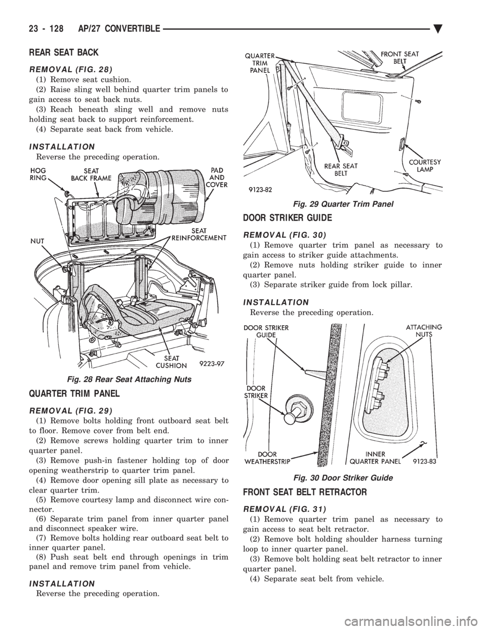
REMOVAL (FIG. 28)
(1) Remove seat cushion.
(2) Raise sling well behind quarter trim panels to
gain access to seat back nuts. (3) Reach beneath sling well and remove nuts
holding seat back to support reinforcement. (4) Separate seat back from vehicle.
INSTALLATION
Reverse the preceding operation.
QUARTER TRIM PANEL
REMOVAL (FIG. 29)
(1) Remove bolts holding front outboard seat belt
to floor. Remove cover from belt end. (2) Remove screws holding quarter trim to inner
quarter panel. (3) Remove push-in fastener holding top of door
opening weatherstrip to quarter trim panel. (4) Remove door opening sill plate as necessary to
clear quarter trim. (5) Remove courtesy lamp and disconnect wire con-
nector. (6) Separate trim panel from inner quarter panel
and disconnect speaker wire. (7) Remove bolts holding rear outboard seat belt to
inner quarter panel. (8) Push seat belt end through openings in trim
panel and remove trim panel from vehicle.
INSTALLATION
Reverse the preceding operation.
DOOR STRIKER GUIDE
REMOVAL (FIG. 30)
(1) Remove quarter trim panel as necessary to
gain access to striker guide attachments. (2) Remove nuts holding striker guide to inner
quarter panel. (3) Separate striker guide from lock pillar.
INSTALLATION
Reverse the preceding operation.
FRONT SEAT BELT RETRACTOR
REMOVAL (FIG. 31)
(1) Remove quarter trim panel as necessary to
gain access to seat belt retractor. (2) Remove bolt holding shoulder harness turning
loop to inner quarter panel. (3) Remove bolt holding seat belt retractor to inner
quarter panel. (4) Separate seat belt from vehicle.
Fig. 28 Rear Seat Attaching Nuts
Fig. 29 Quarter Trim Panel
Fig. 30 Door Striker Guide
23 - 128 AP/27 CONVERTIBLE Ä
Page 2285 of 2438
INSTALLATION
Reverse the preceding operation.
REAR SEAT BELT RETRACTOR
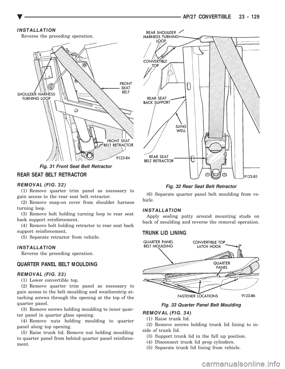
REMOVAL (FIG. 32)
(1) Remove quarter trim panel as necessary to
gain access to the rear seat belt retractor. (2) Remove snap-on cover from shoulder harness
turning loop. (3) Remove bolt holding turning loop to rear seat
back support reinforcement. (4) Remove bolt holding retractor to rear seat back
support reinforcement. (5) Separate retractor from vehicle.
INSTALLATION
Reverse the preceding operation.
QUARTER PANEL BELT MOULDING
REMOVAL (FIG. 33)
(1) Lower convertible top.
(2) Remove quarter trim panel as necessary to
gain access to the belt moulding and weatherstrip at-
taching screws through the opening at the top of the
quarter panel. (3) Remove screws holding moulding to inner quar-
ter panel in quarter glass opening. (4) Remove nuts holding moulding to quarter
panel along top opening. (5) Raise trunk lid. Remove nut holding moulding
to quarter panel from behind quarter panel reinforce-
ment. (6) Separate quarter panel belt moulding from ve-
hicle.
INSTALLATION
Apply sealing putty around mounting studs on
back of moulding and reverse the removal operation.
TRUNK LID LINING
REMOVAL (FIG. 34)
(1) Raise trunk lid.
(2) Remove screws holding trunk lid lining to in-
side of trunk lid. (3) Support trunk lid in the full up position.
(4) Disconnect trunk lid prop cylinders.
(5) Separate trunk lid lining from vehicle.
Fig. 31 Front Seat Belt Retractor
Fig. 32 Rear Seat Belt Retractor
Fig. 33 Quarter Panel Belt Moulding
Ä AP/27 CONVERTIBLE 23 - 129
Page 2288 of 2438
(3) Loosen nuts holding roof rail weatherstrip re-
tainer to roof rail. Shift retainer inboard or outboard
to achieve proper alignment. (4) Tighten nuts to hold retainer to roof rail and
latch top header. (5) Verify weatherstrip sealing and door closing ef-
fort.
QUARTER GLASS AND ROLLER BRACKET
QUARTER GLASS
(1) Verify that door glass is properly aligned.
(2) Loosen nut holding top of quarter glass to rear
roof rail. (3) Shift quarter glass inboard or outboard, for-
ward or rearward to achieve proper alignment. (4) Tighten nut to hold top of quarter glass to rear
roof rail. (5) Verify door glass operation and weatherstrip
sealing.
ROLLER BRACKET
The roller bracket controls the in and out move-
ment at the bottom for the quarter glass. (1) Remove quarter trim panel as necessary to
gain access to the bottom of the quarter glass. (2) Lower convertible top.
(3) Loosen bolts holding roller bracket to quarter
panel reinforcement. (4) Align roller bracket to reduce quarter belt
weatherstrip contact when top is raised and proper
sash weatherstrip compression against the door
glass. (5) Tighten bolts to hold roller to quarter panel
and verify top operation and weatherstrip sealing.
TOP STACK DOWN-STOP
Adjust down-stop in or out to set top stack down
position height.
CAUTION: Avoid setting top stack position too low,
top cover can be pinched and cut between wheel-
house and fourth bow. Seal base of down-stop with silicone after adjust-
ing to prevent water leaks.
TOP STACK UP-STOP
Adjust up-stop in or out to change the contact with
the rear rail. This will effect the fore/aft position of
the No. 1 bow.
FOURTH ROOF BOW SLAT
Adjust the fourth roof bow slat to reduce wrinkles
and bagging around rear window and sail panels. (1) Verify convertible top is up and latched.
(2) Loosen bolts holding the slat to the fourth roof
bow. (3) Slide the bow up or down as necessary and
tighten bolts.
REAR TENSIONER PLATE
Adjust rear tensioner plate by loosening screws, po-
sitioning plate forward or backward, and tightening
screws. Tension can be adjusted on the back of the
top cover by varying contact.
23 - 132 AP/27 CONVERTIBLE Ä
Page 2289 of 2438
AY-VEHICLE BODY COMPONENT SERVICE INDEX
page page
A-Pillar and Roof Rail Mouldings ............ 143
B-Pillar Trim Panel ...................... 143
Body Mouldings ......................... 146
Cowl Panel Trim and Scuff Plates ........... 143
Door Frame Trim Moulding ................ 137
Front Door and Hinge .................... 137
Front Door Glass ........................ 139
Front Door Latch ........................ 138
Front Door Silencer and Water Shield ........ 137
Front Door Trim Panel .................... 136
Front Door Window Regulator .............. 138
Front End Splash Shields ................. 136
Front Seat Belts ........................ 144
Front Seats ............................ 145
Grille AY/P Body ........................ 133
Grille AY/S Body ........................ 133
Grille Opening Panel AY/P Body ............ 134
Grille Opening Panel AY/S Body ............ 134
Head Lining ............................ 142
Hood and Hinges ....................... 134
Hood Latch and Release Cable ............. 135
Hood Ornament AY/P-S .................. 134
Outside Door Handle ..................... 138
Overhead Console ....................... 142 Quarter Trim Panel
...................... 143
Rear Deck Filler Panel ................... 146
Rear Door and Hinge .................... 140
Rear Door Fixed Glass Outer Cover ÐAY-S Body ......................... 141
Rear Door Fixed Window Module ........... 142
Rear Door Frame Trim Moulding ............ 139
Rear Door Glass ........................ 141
Rear Door Glass Lift Plate and Guide Bar ..... 141
Rear Door Latch ........................ 140
Rear Door Outer CoverÐAY-P Body ......... 141
Rear Door Outside Handle ................ 140
Rear Door Silencer and Water Shield ........ 140
Rear Door Trim Panel .................... 139
Rear Door Window Regulator .............. 141
Rear Seat Belts ......................... 144
Rear Seats ............................ 145
Rear Shelf Trim Panel .................... 144
Rear Window Glass ...................... 147
Side View Mirror Trim Cover ............... 137
Trunk Lid .............................. 147
Trunk Lid Hinge ........................ 147
Trunk Lid Torsion Bar .................... 148
Vinyl Roof Bonnet ....................... 146
GRILLE AY/P BODY
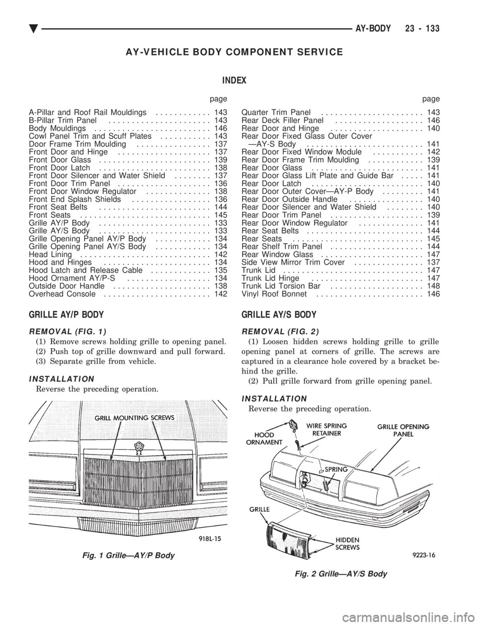
REMOVAL (FIG. 1)
(1) Remove screws holding grille to opening panel.
(2) Push top of grille downward and pull forward.
(3) Separate grille from vehicle.
INSTALLATION
Reverse the preceding operation.
GRILLE AY/S BODY
REMOVAL (FIG. 2)
(1) Loosen hidden screws holding grille to grille
opening panel at corners of grille. The screws are
captured in a clearance hole covered by a bracket be-
hind the grille. (2) Pull grille forward from grille opening panel.
INSTALLATION
Reverse the preceding operation.
Fig. 1 GrilleÐAY/P Body
Fig. 2 GrilleÐAY/S Body
Ä AY-BODY 23 - 133
Page 2292 of 2438
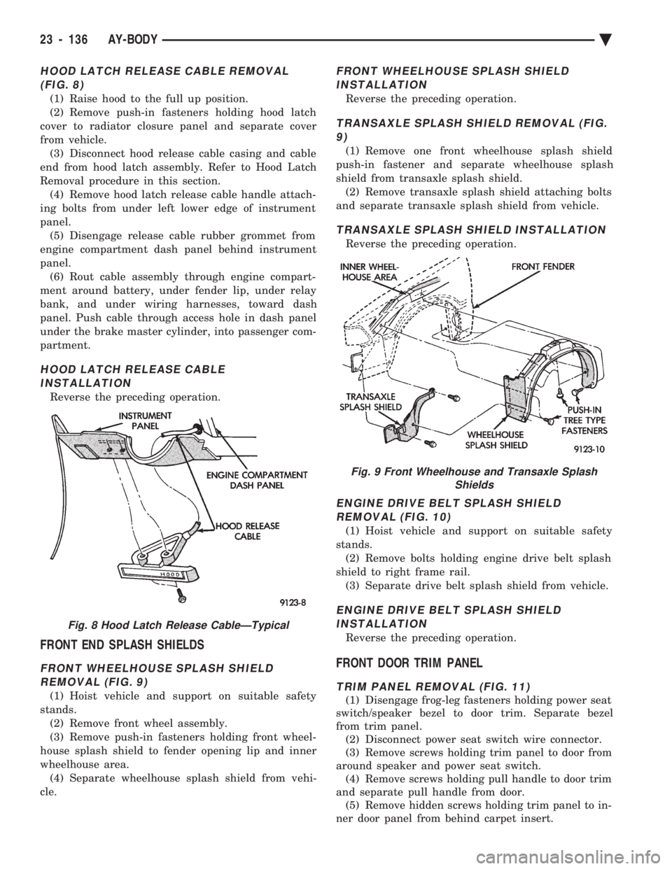
HOOD LATCH RELEASE CABLE REMOVAL (FIG. 8)
(1) Raise hood to the full up position.
(2) Remove push-in fasteners holding hood latch
cover to radiator closure panel and separate cover
from vehicle. (3) Disconnect hood release cable casing and cable
end from hood latch assembly. Refer to Hood Latch
Removal procedure in this section. (4) Remove hood latch release cable handle attach-
ing bolts from under left lower edge of instrument
panel. (5) Disengage release cable rubber grommet from
engine compartment dash panel behind instrument
panel. (6) Rout cable assembly through engine compart-
ment around battery, under fender lip, under relay
bank, and under wiring harnesses, toward dash
panel. Push cable through access hole in dash panel
under the brake master cylinder, into passenger com-
partment.
HOOD LATCH RELEASE CABLE INSTALLATION
Reverse the preceding operation.
FRONT END SPLASH SHIELDS
FRONT WHEELHOUSE SPLASH SHIELDREMOVAL (FIG. 9)
(1) Hoist vehicle and support on suitable safety
stands. (2) Remove front wheel assembly.
(3) Remove push-in fasteners holding front wheel-
house splash shield to fender opening lip and inner
wheelhouse area. (4) Separate wheelhouse splash shield from vehi-
cle.
FRONT WHEELHOUSE SPLASH SHIELD INSTALLATION
Reverse the preceding operation.
TRANSAXLE SPLASH SHIELD REMOVAL (FIG.9)
(1) Remove one front wheelhouse splash shield
push-in fastener and separate wheelhouse splash
shield from transaxle splash shield. (2) Remove transaxle splash shield attaching bolts
and separate transaxle splash shield from vehicle.
TRANSAXLE SPLASH SHIELD INSTALLATION
Reverse the preceding operation.
ENGINE DRIVE BELT SPLASH SHIELD REMOVAL (FIG. 10)
(1) Hoist vehicle and support on suitable safety
stands. (2) Remove bolts holding engine drive belt splash
shield to right frame rail. (3) Separate drive belt splash shield from vehicle.
ENGINE DRIVE BELT SPLASH SHIELDINSTALLATION
Reverse the preceding operation.
FRONT DOOR TRIM PANEL
TRIM PANEL REMOVAL (FIG. 11)
(1) Disengage frog-leg fasteners holding power seat
switch/speaker bezel to door trim. Separate bezel
from trim panel. (2) Disconnect power seat switch wire connector.
(3) Remove screws holding trim panel to door from
around speaker and power seat switch. (4) Remove screws holding pull handle to door trim
and separate pull handle from door. (5) Remove hidden screws holding trim panel to in-
ner door panel from behind carpet insert.
Fig. 8 Hood Latch Release CableÐTypical
Fig. 9 Front Wheelhouse and Transaxle Splash Shields
23 - 136 AY-BODY Ä
Page 2293 of 2438
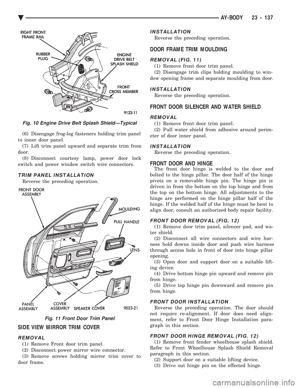
(6) Disengage frog-leg fasteners holding trim panel
to inner door panel. (7) Lift trim panel upward and separate trim from
door. (8) Disconnect courtesy lamp, power door lock
switch and power window switch wire connectors.
TRIM PANEL INSTALLATION
Reverse the preceding operation.
SIDE VIEW MIRROR TRIM COVER
REMOVAL
(1) Remove Front door trim panel.
(2) Disconnect power mirror wire connector.
(3) Remove screws holding mirror trim cover to
door frame.
INSTALLATION
Reverse the preceding operation.
DOOR FRAME TRIM MOULDING
REMOVAL (FIG. 11)
(1) Remove front door trim panel.
(2) Disengage trim clips holding moulding to win-
dow opening frame and separate moulding from door.
INSTALLATION
Reverse the preceding operation.
FRONT DOOR SILENCER AND WATER SHIELD
REMOVAL
(1) Remove front door trim panel.
(2) Pull water shield from adhesive around perim-
eter of door inner panel.
INSTALLATION
Reverse the preceding operation.
FRONT DOOR AND HINGE
The front door hinge is welded to the door and
bolted to the hinge pillar. The door half of the hinge
pivots on a removable hinge pin. The hinge pin is
driven in from the bottom on the top hinge and from
the top on the bottom hinge. All adjustments to the
hinge are performed on the hinge pillar half of the
hinge. If the welded half of the hinge must be bent to
align door, consult an authorized body repair facility.
FRONT DOOR REMOVAL (FIG. 12)
(1) Remove door trim panel, silencer pad, and wa-
ter shield. (2) Disconnect all wire connectors and wire har-
ness hold downs inside door and push wire harness
through access hole in front of door into hinge pillar
opening. (3) Open door and support door on a suitable lift-
ing device. (4) Drive bottom hinge pin upward and remove pin
from hinge. (5) Drive top hinge pin downward and remove pin
from hinge.
FRONT DOOR INSTALLATION
Reverse the preceding operation. The door should
not require re-alignment. If door does need align-
ment, refer to Front Door Hinge Installation para-
graph in this section.
FRONT DOOR HINGE REMOVAL (FIG. 12)
(1) Remove front fender wheelhouse splash shield.
Refer to Front Wheelhouse Splash Shield Removal
paragraph in this section. (2) Support door on a suitable lifting device.
(3) Drive out hinge pin on the effected hinge.
Fig. 10 Engine Drive Belt Splash ShieldÐTypical
Fig. 11 Front Door Trim Panel
Ä AY-BODY 23 - 137
Page 2299 of 2438
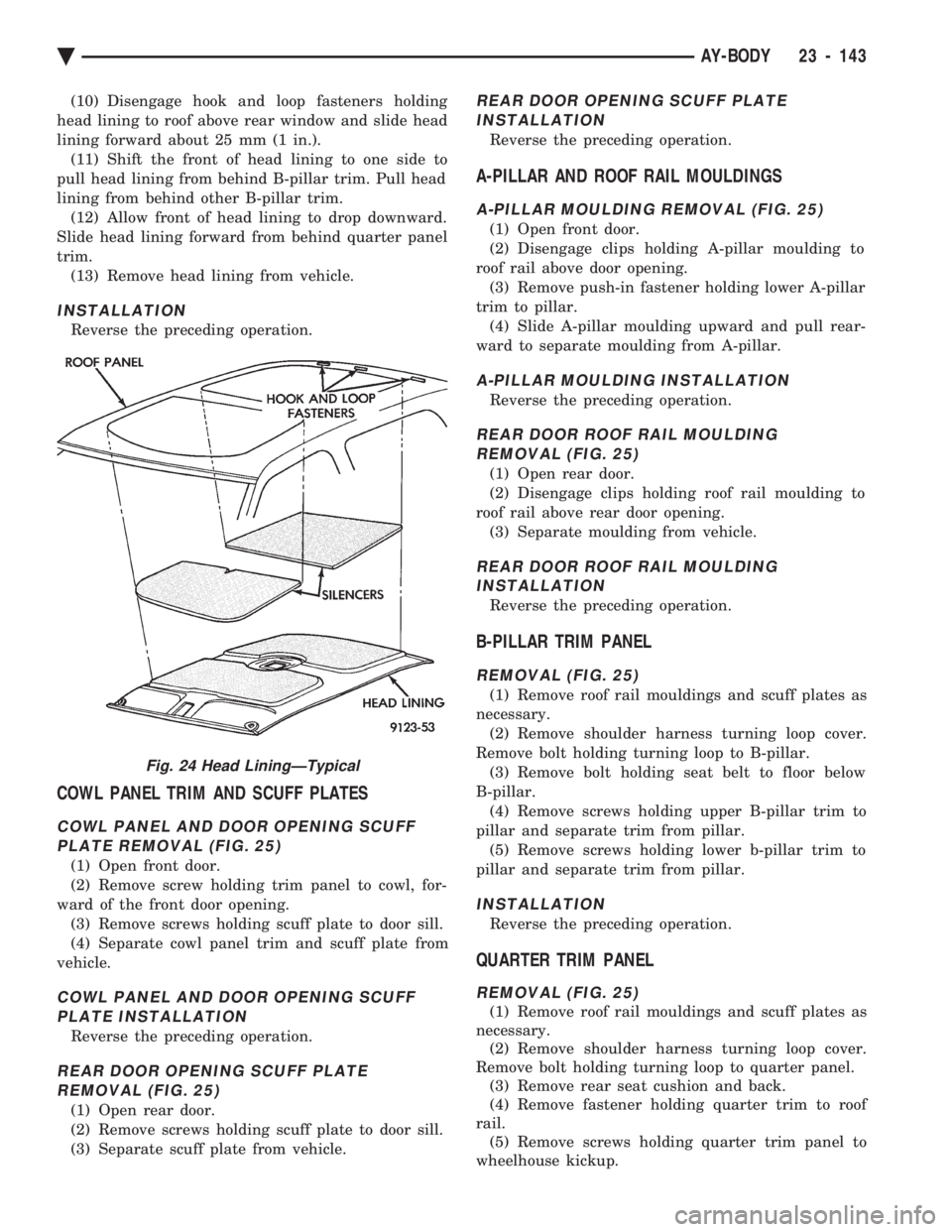
(10) Disengage hook and loop fasteners holding
head lining to roof above rear window and slide head
lining forward about 25 mm (1 in.). (11) Shift the front of head lining to one side to
pull head lining from behind B-pillar trim. Pull head
lining from behind other B-pillar trim. (12) Allow front of head lining to drop downward.
Slide head lining forward from behind quarter panel
trim. (13) Remove head lining from vehicle.
INSTALLATION
Reverse the preceding operation.
COWL PANEL TRIM AND SCUFF PLATES
COWL PANEL AND DOOR OPENING SCUFFPLATE REMOVAL (FIG. 25)
(1) Open front door.
(2) Remove screw holding trim panel to cowl, for-
ward of the front door opening. (3) Remove screws holding scuff plate to door sill.
(4) Separate cowl panel trim and scuff plate from
vehicle.
COWL PANEL AND DOOR OPENING SCUFF PLATE INSTALLATION
Reverse the preceding operation.
REAR DOOR OPENING SCUFF PLATEREMOVAL (FIG. 25)
(1) Open rear door.
(2) Remove screws holding scuff plate to door sill.
(3) Separate scuff plate from vehicle.
REAR DOOR OPENING SCUFF PLATEINSTALLATION
Reverse the preceding operation.
A-PILLAR AND ROOF RAIL MOULDINGS
A-PILLAR MOULDING REMOVAL (FIG. 25)
(1) Open front door.
(2) Disengage clips holding A-pillar moulding to
roof rail above door opening. (3) Remove push-in fastener holding lower A-pillar
trim to pillar. (4) Slide A-pillar moulding upward and pull rear-
ward to separate moulding from A-pillar.
A-PILLAR MOULDING INSTALLATION
Reverse the preceding operation.
REAR DOOR ROOF RAIL MOULDING REMOVAL (FIG. 25)
(1) Open rear door.
(2) Disengage clips holding roof rail moulding to
roof rail above rear door opening. (3) Separate moulding from vehicle.
REAR DOOR ROOF RAIL MOULDINGINSTALLATION
Reverse the preceding operation.
B-PILLAR TRIM PANEL
REMOVAL (FIG. 25)
(1) Remove roof rail mouldings and scuff plates as
necessary. (2) Remove shoulder harness turning loop cover.
Remove bolt holding turning loop to B-pillar. (3) Remove bolt holding seat belt to floor below
B-pillar. (4) Remove screws holding upper B-pillar trim to
pillar and separate trim from pillar. (5) Remove screws holding lower b-pillar trim to
pillar and separate trim from pillar.
INSTALLATION
Reverse the preceding operation.
QUARTER TRIM PANEL
REMOVAL (FIG. 25)
(1) Remove roof rail mouldings and scuff plates as
necessary. (2) Remove shoulder harness turning loop cover.
Remove bolt holding turning loop to quarter panel. (3) Remove rear seat cushion and back.
(4) Remove fastener holding quarter trim to roof
rail. (5) Remove screws holding quarter trim panel to
wheelhouse kickup.
Fig. 24 Head LiningÐTypical
Ä AY-BODY 23 - 143
Page 2300 of 2438
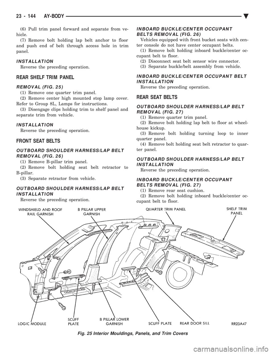
(6) Pull trim panel forward and separate from ve-
hicle. (7) Remove bolt holding lap belt anchor to floor
and push end of belt through access hole in trim
panel.
INSTALLATION
Reverse the preceding operation.
REAR SHELF TRIM PANEL
REMOVAL (FIG. 25)
(1) Remove one quarter trim panel.
(2) Remove center high mounted stop lamp cover.
Refer to Group 8L, Lamps for instructions. (3) Disengage clips holding trim to shelf panel and
separate trim from vehicle.
INSTALLATION
Reverse the preceding operation.
FRONT SEAT BELTS
OUTBOARD SHOULDER HARNESS/LAP BELT REMOVAL (FIG. 26)
(1) Remove B-pillar trim panel.
(2) Remove bolt holding seat belt retractor to
B-pillar. (3) Separate retractor from vehicle.
OUTBOARD SHOULDER HARNESS/LAP BELTINSTALLATION
Reverse the preceding operation.
INBOARD BUCKLE/CENTER OCCUPANT BELTS REMOVAL (FIG. 26)
Vehicles equipped with front bucket seats with cen-
ter console do not have center occupant belts. (1) Remove bolt holding inboard buckle/center oc-
cupant belt to floor. (2) Disconnect seat belt sensor wire connector.
(3) Separate buckle/belt assembly from vehicle.
INBOARD BUCKLE/CENTER OCCUPANT BELT INSTALLATION
Reverse the preceding operation.
REAR SEAT BELTS
OUTBOARD SHOULDER HARNESS/LAP BELTREMOVAL (FIG. 27)
(1) Remove quarter trim panel.
(2) Remove bolt holding lap belt to floor at wheel-
house kickup. (3) Remove bolt holding turning loop to inner
quarter panel. (4) Remove bolt holding seat belt retractor to quar-
ter panel.
OUTBOARD SHOULDER HARNESS/LAP BELT INSTALLATION
Reverse the preceding operation.
INBOARD BUCKLE/CENTER OCCUPANTBELTS REMOVAL (FIG. 27)
(1) Remove rear seat cushion.
(2) Remove bolt holding inboard buckle/center oc-
cupant belt to floor.
Fig. 25 Interior Mouldings, Panels, and Trim Covers
23 - 144 AY-BODY Ä