1993 CHEVROLET PLYMOUTH ACCLAIM belt
[x] Cancel search: beltPage 1601 of 2438
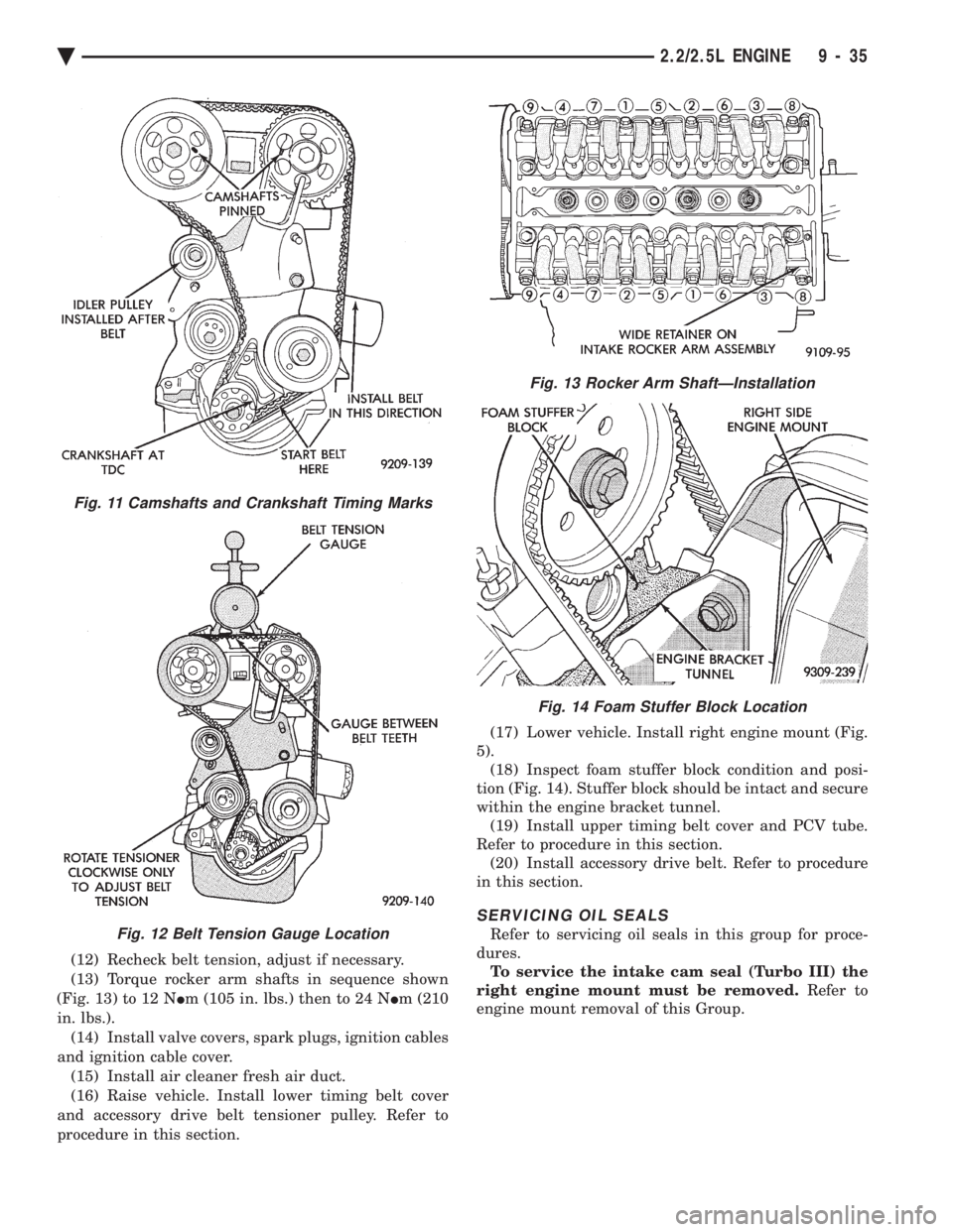
(12) Recheck belt tension, adjust if necessary.
(13) Torque rocker arm shafts in sequence shown
(Fig. 13) to 12 N Im (105 in. lbs.) then to 24 N Im (210
in. lbs.). (14) Install valve covers, spark plugs, ignition cables
and ignition cable cover. (15) Install air cleaner fresh air duct.
(16) Raise vehicle. Install lower timing belt cover
and accessory drive belt tensioner pulley. Refer to
procedure in this section. (17) Lower vehicle. Install right engine mount (Fig.
5). (18) Inspect foam stuffer block condition and posi-
tion (Fig. 14). Stuffer block should be intact and secure
within the engine bracket tunnel. (19) Install upper timing belt cover and PCV tube.
Refer to procedure in this section. (20) Install accessory drive belt. Refer to procedure
in this section.
SERVICING OIL SEALS
Refer to servicing oil seals in this group for proce-
dures. To service the intake cam seal (Turbo III) the
right engine mount must be removed. Refer to
engine mount removal of this Group.
Fig. 13 Rocker Arm ShaftÐInstallation
Fig. 14 Foam Stuffer Block Location
Fig. 11 Camshafts and Crankshaft Timing Marks
Fig. 12 Belt Tension Gauge Location
Ä 2.2/2.5L ENGINE 9 - 35
Page 1608 of 2438
CRANKSHAFT OIL SEALS SERVICE
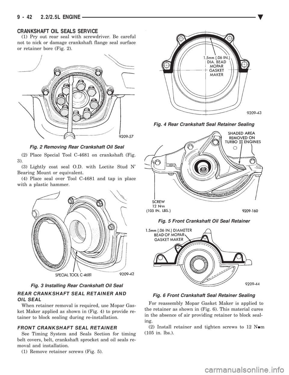
(1) Pry out rear seal with screwdriver. Be careful
not to nick or damage crankshaft flange seal surface
or retainer bore (Fig. 2).
(2) Place Special Tool C-4681 on crankshaft (Fig.
3). (3) Lightly coat seal O.D. with Loctite Stud N'
Bearing Mount or equivalent. (4) Place seal over Tool C-4681 and tap in place
with a plastic hammer.
REAR CRANKSHAFT SEAL RETAINER AND OIL SEAL
When retainer removal is required, use Mopar Gas-
ket Maker applied as shown in (Fig. 4) to provide re-
tainer to block sealing during re-installation.
FRONT CRANKSHAFT SEAL RETAINER
See Timing System and Seals Section for timing
belt covers, belt, crankshaft sprocket and oil seals re-
moval and installation. (1) Remove retainer screws (Fig. 5). For reassembly Mopar Gasket Maker is applied to
the retainer as shown in (Fig. 6). This material cures
in the absence of air providing retainer to block seal-
ing. (2) Install retainer and tighten screws to 12 N Im
(105 in. lbs.).
Fig. 2 Removing Rear Crankshaft Oil Seal
Fig. 3 Installing Rear Crankshaft Oil Seal
Fig. 4 Rear Crankshaft Seal Retainer Sealing
Fig. 5 Front Crankshaft Oil Seal Retainer
Fig. 6 Front Crankshaft Seal Retainer Sealing
9 - 42 2.2/2.5L ENGINE Ä
Page 1610 of 2438
cap and a crankshaft cheek, using care not to dam-
age any bearing surface. Do notloosen main bearing
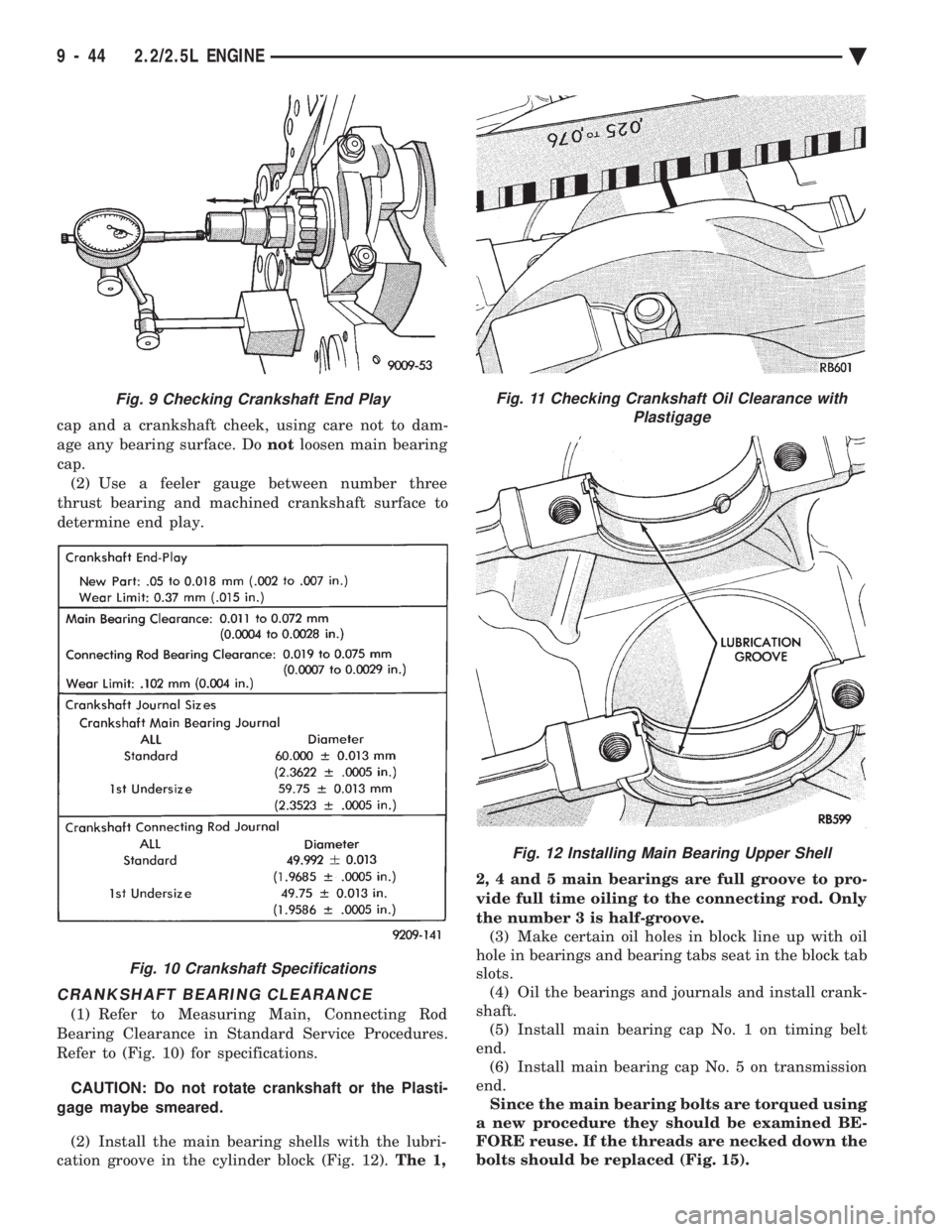
cap. (2) Use a feeler gauge between number three
thrust bearing and machined crankshaft surface to
determine end play.
CRANKSHAFT BEARING CLEARANCE
(1) Refer to Measuring Main, Connecting Rod
Bearing Clearance in Standard Service Procedures.
Refer to (Fig. 10) for specifications.
CAUTION: Do not rotate crankshaft or the Plasti-
gage maybe smeared.
(2) Install the main bearing shells with the lubri-
cation groove in the cylinder block (Fig. 12). The 1, 2, 4 and 5 main bearings are full groove to pro-
vide full time oiling to the connecting rod. Only
the number 3 is half-groove.
(3) Make certain oil holes in block line up with oil
hole in bearings and bearing tabs seat in the block tab
slots. (4) Oil the bearings and journals and install crank-
shaft. (5) Install main bearing cap No. 1 on timing belt
end. (6) Install main bearing cap No. 5 on transmission
end. Since the main bearing bolts are torqued using
a new procedure they should be examined BE-
FORE reuse. If the threads are necked down the
bolts should be replaced (Fig. 15).
Fig. 9 Checking Crankshaft End Play
Fig. 10 Crankshaft Specifications
Fig. 11 Checking Crankshaft Oil Clearance with Plastigage
Fig. 12 Installing Main Bearing Upper Shell
9 - 44 2.2/2.5L ENGINE Ä
Page 1615 of 2438
CYLINDER BLOCK, PISTON AND CONNECTING ROD ASSEMBLY SERVICE
PISTON AND CONNECTING RODÐREMOVAL
(1) Remove top ridge of cylinder bores with a reliable
ridge reamer before removing pistons from cylinder
block. Be sure to keep tops of pistons covered
during this operation . Mark piston with matching
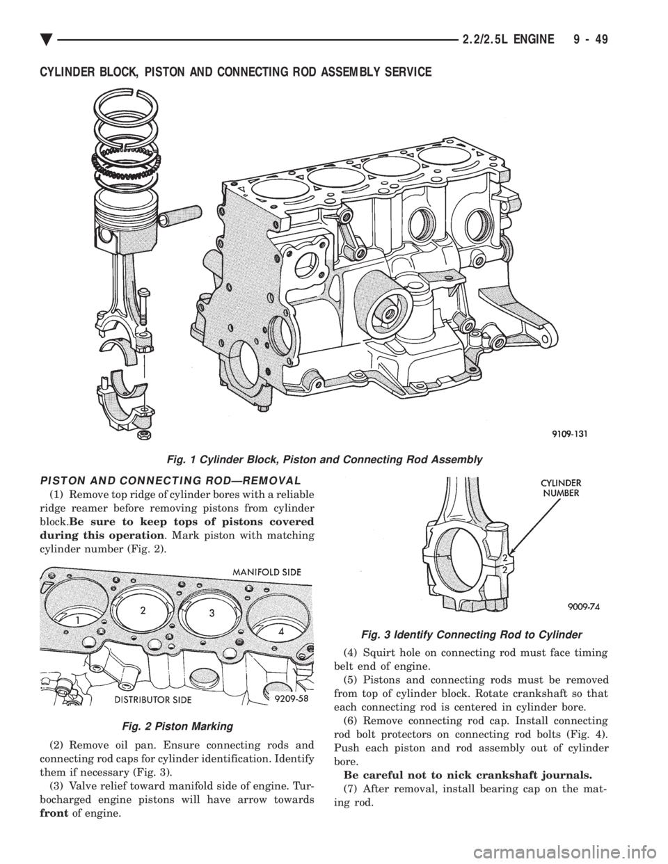
cylinder number (Fig. 2).
(2) Remove oil pan. Ensure connecting rods and
connecting rod caps for cylinder identification. Identify
them if necessary (Fig. 3). (3) Valve relief toward manifold side of engine. Tur-
bocharged engine pistons will have arrow towards
front of engine. (4) Squirt hole on connecting rod must face timing
belt end of engine. (5) Pistons and connecting rods must be removed
from top of cylinder block. Rotate crankshaft so that
each connecting rod is centered in cylinder bore. (6) Remove connecting rod cap. Install connecting
rod bolt protectors on connecting rod bolts (Fig. 4).
Push each piston and rod assembly out of cylinder
bore. Be careful not to nick crankshaft journals.
(7) After removal, install bearing cap on the mat-
ing rod.
Fig. 1 Cylinder Block, Piston and Connecting Rod Assembly
Fig. 3 Identify Connecting Rod to Cylinder
Fig. 2 Piston Marking
Ä 2.2/2.5L ENGINE 9 - 49
Page 1632 of 2438
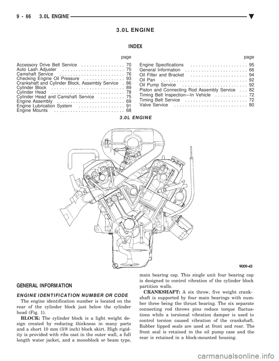
3.0L ENGINE INDEX
page page
Accessory Drive Belt Service ................ 70
Auto Lash Adjuster ....................... 75
Camshaft Service ........................ 76
Checking Engine Oil Pressure ............... 93
Crankshaft and Cylinder Block, Assembly Service . 86
Cylinder Block ........................... 89
Cylinder Head ........................... 78
Cylinder Head and Camshaft Service ......... 75
Engine Assembly ......................... 69
Engine Lubrication System ................. 91
Engine Mounts .......................... 68 Engine Specifications
..................... 95
General Information ....................... 66
Oil Filter and Bracket ..................... 94
Oil Pan ................................ 92
Oil Pump Service ........................ 92
Piston and Connecting Rod Assembly Service . . . 82
Timing Belt InspectionÐIn Vehicle ............ 72
Timing Belt Service ....................... 72
Valve Service ........................... 80
GENERAL INFORMATION
ENGINE IDENTIFICATION NUMBER OR CODE
The engine identification number is located on the
rear of the cylinder block just below the cylinder
head (Fig. 1). BLOCK: The cylinder block is a light weight de-
sign created by reducing thickness in many parts
and a short 10 mm (3/8 inch) block skirt. High rigid-
ity is provided with ribs cast in the outer wall, a full
length water jacket, and a monoblock or beam type, main bearing cap. This single unit four bearing cap
is designed to control vibration of the cylinder block
partition walls.
CRANKSHAFT: A six throw, five weight crank-
shaft is supported by four main bearings with num-
ber three being the thrust bearing. The six separate
connecting rod throws pins reduce torque fluctua-
tions while a torsional vibration damper is used to
control torsion caused vibration of the crankshaft.
Rubber lipped seals are used at front and rear. The
front seal is retained in the oil pump case and the
rear is retained in a block-mounted housing.
3.0L ENGINE
9 - 66 3.0L ENGINE Ä
Page 1633 of 2438
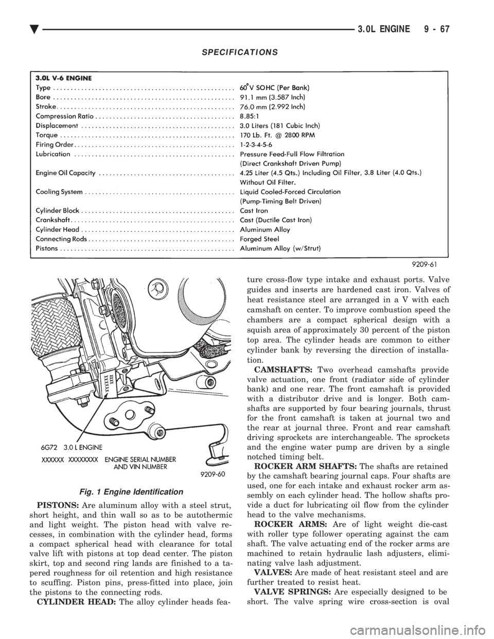
PISTONS: Are aluminum alloy with a steel strut,
short height, and thin wall so as to be autothermic
and light weight. The piston head with valve re-
cesses, in combination with the cylinder head, forms
a compact spherical head with clearance for total
valve lift with pistons at top dead center. The piston
skirt, top and second ring lands are finished to a ta-
pered roughness for oil retention and high resistance
to scuffing. Piston pins, press-fitted into place, join
the pistons to the connecting rods. CYLINDER HEAD: The alloy cylinder heads fea- ture cross-flow type intake and exhaust ports. Valve
guides and inserts are hardened cast iron. Valves of
heat resistance steel are arranged i
n a V with each
camshaft on center. To improve combustion speed the
chambers are a compact spherical design with a
squish area of approximately 30 percent of the piston
top area. The cylinder heads are common to either
cylinder bank by reversing the direction of installa-
tion. CAMSHAFTS: Two overhead camshafts provide
valve actuation, one front (radiator side of cylinder
bank) and one rear. The front camshaft is provided
with a distributor drive and is longer. Both cam-
shafts are supported by four bearing journals, thrust
for the front camshaft is taken at journal two and
the rear at journal three. Front and rear camshaft
driving sprockets are interchangeable. The sprockets
and the engine water pump are driven by a single
notched timing belt. ROCKER ARM SHAFTS: The shafts are retained
by the camshaft bearing journal caps. Four shafts are
used, one for each intake and exhaust rocker arm as-
sembly on each cylinder head. The hollow shafts pro-
vide a duct for lubricating oil flow from the cylinder
head to the valve mechanisms. ROCKER ARMS: Are of light weight die-cast
with roller type follower operating against the cam
shaft. The valve actuating end of the rocker arms are
machined to retain hydraulic lash adjusters, elimi-
nating valve lash adjustment. VALVES: Are made of heat resistant steel and are
further treated to resist heat. VALVE SPRINGS: Are especially designed to be
short. The valve spring wire cross-section is oval
SPECIFICATIONS
Fig. 1 Engine Identification
Ä 3.0L ENGINE 9 - 67
Page 1636 of 2438
(c) Remove LEFT insulator through bolt from in-
side wheelhouse or insulator bracket to transmis-
sion screws.
(22) Remove engine.
INSTALLATION
(1) Attach hoist and lower engine into engine com-
partment. (2) Align engine mounts and install but do not
tighten until all mounting bolts have been installed.
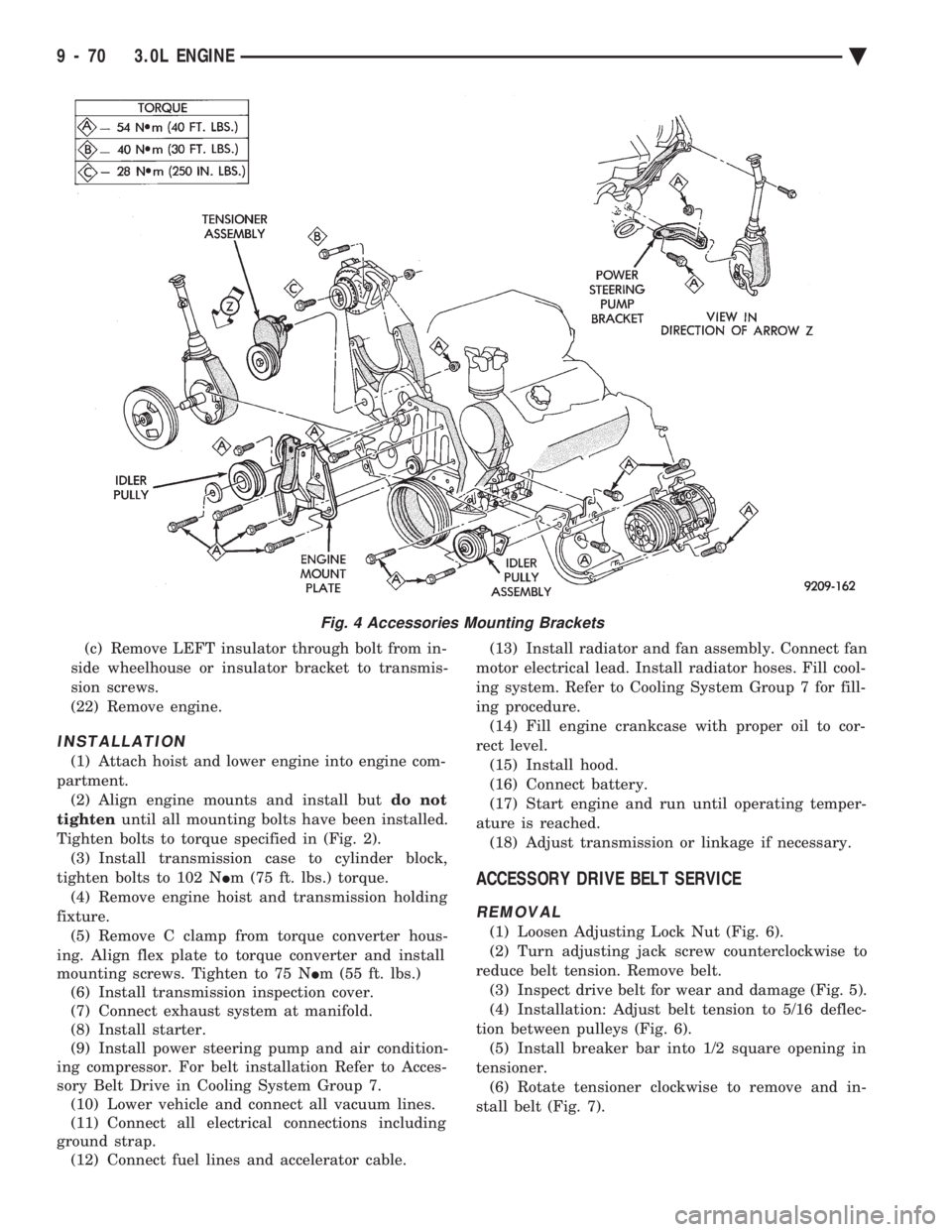
Tighten bolts to torque specified in (Fig. 2). (3) Install transmission case to cylinder block,
tighten bolts to 102 N Im (75 ft. lbs.) torque.
(4) Remove engine hoist and transmission holding
fixture. (5) Remove C clamp from torque converter hous-
ing. Align flex plate to torque converter and install
mounting screws. Tighten to 75 N Im (55 ft. lbs.)
(6) Install transmission inspection cover.
(7) Connect exhaust system at manifold.
(8) Install starter.
(9) Install power steering pump and air condition-
ing compressor. For belt installation Refer to Acces-
sory Belt Drive in Cooling System Group 7. (10) Lower vehicle and connect all vacuum lines.
(11) Connect all electrical connections including
ground strap. (12) Connect fuel lines and accelerator cable. (13) Install radiator and fan assembly. Connect fan
motor electrical lead. Install radiator hoses. Fill cool-
ing system. Refer to Cooling System Group 7 for fill-
ing procedure. (14) Fill engine crankcase with proper oil to cor-
rect level. (15) Install hood.
(16) Connect battery.
(17) Start engine and run until operating temper-
ature is reached. (18) Adjust transmission or linkage if necessary.
ACCESSORY DRIVE BELT SERVICE
REMOVAL
(1) Loosen Adjusting Lock Nut (Fig. 6).
(2) Turn adjusting jack screw counterclockwise to
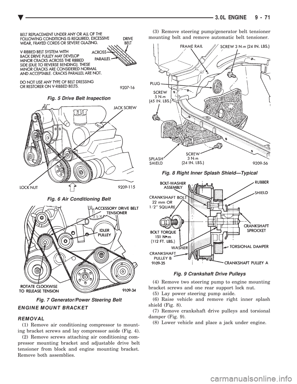
reduce belt tension. Remove belt. (3) Inspect drive belt for wear and damage (Fig. 5).
(4) Installation: Adjust belt tension to 5/16 deflec-
tion between pulleys (Fig. 6). (5) Install breaker bar into 1/2 square opening in
tensioner. (6) Rotate tensioner clockwise to remove and in-
stall belt (Fig. 7).
Fig. 4 Accessories Mounting Brackets
9 - 70 3.0L ENGINE Ä
Page 1637 of 2438
ENGINE MOUNT BRACKET REMOVAL
(1) Remove air conditioning compressor to mount-
ing bracket screws and lay compressor aside (Fig. 4). (2) Remove screws attaching air conditioning com-
pressor mounting bracket and adjustable drive belt
tensioner from block and engine mounting bracket.
Remove both assemblies. (3) Remove steering pump/generator belt tensioner
mounting bolt and remove automatic belt tensioner.
(4) Remove two steering pump to engine mounting
bracket screws and one rear support lock nut. (5) Lay power steering pump aside.
(6) Raise vehicle and remove right inner splash
shield (Fig. 8). (7) Remove crankshaft drive pulleys and torsional
damper (Fig. 9). (8) Lower vehicle and place a jack under engine.
Fig. 5 Drive Belt Inspection
Fig. 6 Air Conditioning Belt
Fig. 7 Generator/Power Steering Belt
Fig. 8 Right Inner Splash ShieldÐTypical
Fig. 9 Crankshaft Drive Pulleys
Ä 3.0L ENGINE 9 - 71