1993 CHEVROLET PLYMOUTH ACCLAIM belt
[x] Cancel search: beltPage 1677 of 2438
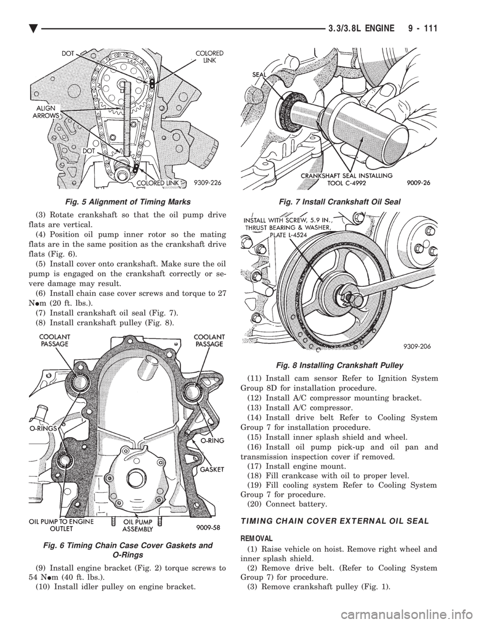
(3) Rotate crankshaft so that the oil pump drive
flats are vertical. (4) Position oil pump inner rotor so the mating
flats are in the same position as the crankshaft drive
flats (Fig. 6). (5) Install cover onto crankshaft. Make sure the oil
pump is engaged on the crankshaft correctly or se-
vere damage may result. (6) Install chain case cover screws and torque to 27
N Im (20 ft. lbs.).
(7) Install crankshaft oil seal (Fig. 7).
(8) Install crankshaft pulley (Fig. 8).
(9) Install engine bracket (Fig. 2) torque screws to
54 N Im (40 ft. lbs.).
(10) Install idler pulley on engine bracket. (11) Install cam sensor Refer to Ignition System
Group 8D for installation procedure. (12) Install A/C compressor mounting bracket.
(13) Install A/C compressor.
(14) Install drive belt Refer to Cooling System
Group 7 for installation procedure. (15) Install inner splash shield and wheel.
(16) Install oil pump pick-up and oil pan and
transmission inspection cover if removed. (17) Install engine mount.
(18) Fill crankcase with oil to proper level.
(19) Fill cooling system Refer to Cooling System
Group 7 for procedure. (20) Connect battery.
TIMING CHAIN COVER EXTERNAL OIL SEAL
REMOVAL
(1) Raise vehicle on hoist. Remove right wheel and
inner splash shield. (2) Remove drive belt. (Refer to Cooling System
Group 7) for procedure. (3) Remove crankshaft pulley (Fig. 1).
Fig. 5 Alignment of Timing Marks
Fig. 6 Timing Chain Case Cover Gaskets and O-Rings
Fig. 7 Install Crankshaft Oil Seal
Fig. 8 Installing Crankshaft Pulley
Ä 3.3/3.8L ENGINE 9 - 111
Page 1678 of 2438
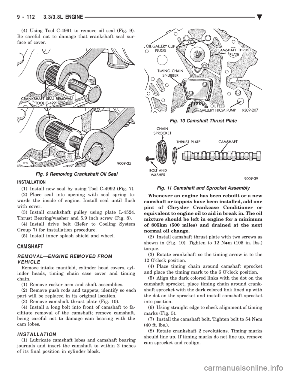
(4) Using Tool C-4991 to remove oil seal (Fig. 9).
Be careful not to damage that crankshaft seal sur-
face of cover.
INSTALLATION (1) Install new seal by using Tool C-4992 (Fig. 7).
(2) Place seal into opening with seal spring to-
wards the inside of engine. Install seal until flush
with cover. (3) Install crankshaft pulley using plate L-4524.
Thrust Bearing/washer and 5.9 inch screw (Fig. 8). (4) Install drive belt (Refer to Cooling System
Group 7) for installation procedure. (5) Install inner splash shield and wheel.
CAMSHAFT
REMOVALÐENGINE REMOVED FROM VEHICLE
Remove intake manifold, cylinder head covers, cyl-
inder heads, timing chain case cover and timing
chain. (1) Remove rocker arm and shaft assemblies.
(2) Remove push rods and tappets; identify so each
part will be replaced in its original location. (3) Remove camshaft thrust plate (Fig. 10).
(4) Install a long bolt into front of camshaft to fa-
cilitate removal of the camshaft; remove camshaft,
being careful not to damage cam bearing with the
cam lobes.
INSTALLATION
(1) Lubricate camshaft lobes and camshaft bearing
journals and insert the camshaft to within 2 inches
of its final position in cylinder block. Whenever an engine has been rebuilt or a new
camshaft or tappets have been installed, add one
pint of Chrysler Crankcase Conditioner or
equivalent to engine oil to aid in break in. The oil
mixture should be left in engine for a minimum
of 805km (500 miles) and drained at the next
normal oil change. (2) Install camshaft thrust plate with two screws as
shown in (Fig. 10). Tighten to 12 N Im (105 in. lbs.)
torque. (3) Rotate crankshaft so the timing arrow is to the
12 O'clock position. (4) Place timing chain around camshaft sprocket
and place the timing mark to the 6 O'clock position. (5) Align the dark colored links with the dot on the
camshaft sprocket, place timing chain around crank-
shaft sprocket with the dark colored link lined up with
the dot on the sprocket and install camshaft sprocket
into position. (6) Using straight edge to check alignment of timing
marks (Fig. 5). (7) Install the camshaft bolt. Tighten bolt to 54 N Im
(40 ft. lbs.). (8) Rotate crankshaft 2 revolutions. Timing marks
should line up. If timing marks do not line up, remove
cam sprocket and realign.
Fig. 9 Removing Crankshaft Oil Seal
Fig. 10 Camshaft Thrust Plate
Fig. 11 Camshaft and Sprocket Assembly
9 - 112 3.3/3.8L ENGINE Ä
Page 1702 of 2438
for diagnostic and service procedures on the air control
valve and temperature sensor located in the air
cleaner.
INTAKE AND EXHAUST MANIFOLDS SERVICEÐTBI
ENGINE
Intake and exhaust manifolds use a one piece gasket.
Service procedures requiring removal and installation
( of either ) must include both manifolds.
FUEL SYSTEM PRESSURE RELEASE PROCE- DURE
The Fuel System is under a constant pressure
of at least 265 kPa (39 psi). Before servicing the
fuel pump, fuel lines, fuel filter, throttle body or
fuel injector, the fuel system pressure must be
released. (a) Loosen fuel filler cap to release fuel tank pres-
sure. (b) Disconnect injector wiring harness from engine
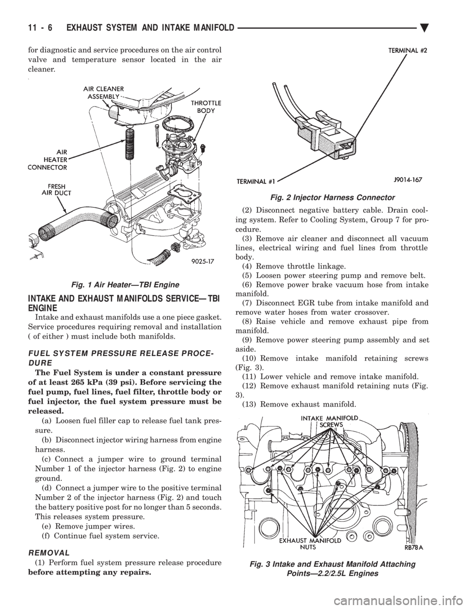
harness. (c) Connect a jumper wire to ground terminal
Number 1 of the injector harness (Fig. 2) to engine
ground. (d) Connect a jumper wire to the positive terminal
Number 2 of the injector harness (Fig. 2) and touch
the battery positive post for no longer than 5 seconds.
This releases system pressure. (e) Remove jumper wires.
(f) Continue fuel system service.
REMOVAL
(1) Perform fuel system pressure release procedure
before attempting any repairs. (2) Disconnect negative battery cable. Drain cool-
ing system. Refer to Cooling System, Group 7 for pro-
cedure. (3) Remove air cleaner and disconnect all vacuum
lines, electrical wiring and fuel lines from throttle
body. (4) Remove throttle linkage.
(5) Loosen power steering pump and remove belt.
(6) Remove power brake vacuum hose from intake
manifold. (7) Disconnect EGR tube from intake manifold and
remove water hoses from water crossover. (8) Raise vehicle and remove exhaust pipe from
manifold. (9) Remove power steering pump assembly and set
aside. (10) Remove intake manifold retaining screws
(Fig. 3). (11) Lower vehicle and remove intake manifold.
(12) Remove exhaust manifold retaining nuts (Fig.
3). (13) Remove exhaust manifold.
Fig. 2 Injector Harness Connector
Fig. 3 Intake and Exhaust Manifold Attaching PointsÐ2.2/2.5L Engines
Fig. 1 Air HeaterÐTBI Engine
11 - 6 EXHAUST SYSTEM AND INTAKE MANIFOLD Ä
Page 1729 of 2438
(2) Remove nuts holding bumper fascia to quarter
panels. (3) Remove fasteners holding bumper fascia to
wheel opening flange. (4) Disconnect license plate lamp wire connectors.
(5) Remove bolts holding bumper to rear closure
panel. (6) Remove nuts holding bumper to energy ab-
sorber units. (7) Separate bumper from vehicle.
INSTALLATION
Reverse the preceding operation.
AG-VEHICLE REAR BUMPER
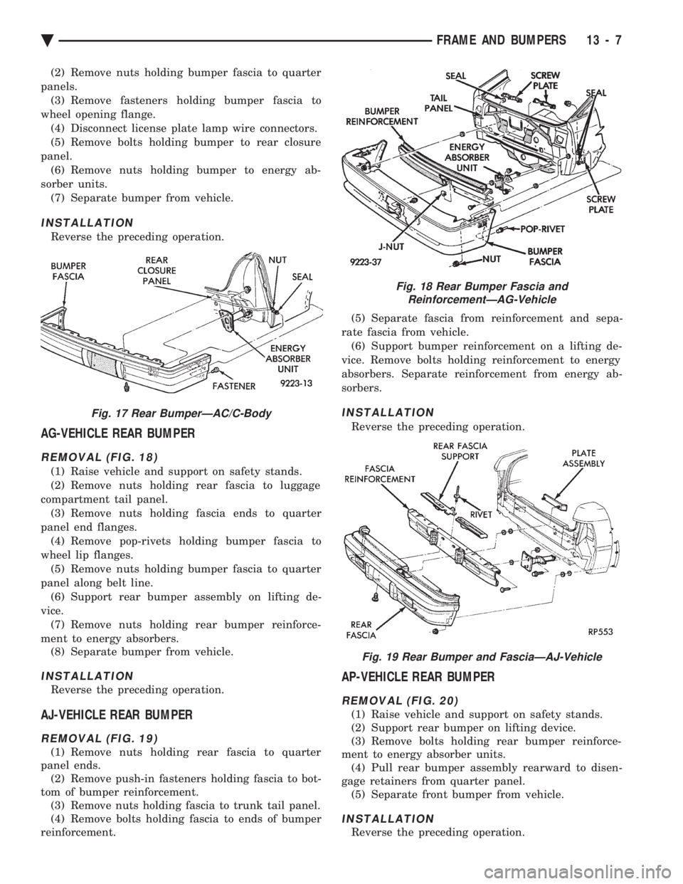
REMOVAL (FIG. 18)
(1) Raise vehicle and support on safety stands.
(2) Remove nuts holding rear fascia to luggage
compartment tail panel. (3) Remove nuts holding fascia ends to quarter
panel end flanges. (4) Remove pop-rivets holding bumper fascia to
wheel lip flanges. (5) Remove nuts holding bumper fascia to quarter
panel along belt line. (6) Support rear bumper assembly on lifting de-
vice. (7) Remove nuts holding rear bumper reinforce-
ment to energy absorbers. (8) Separate bumper from vehicle.
INSTALLATION
Reverse the preceding operation.
AJ-VEHICLE REAR BUMPER
REMOVAL (FIG. 19)
(1) Remove nuts holding rear fascia to quarter
panel ends. (2) Remove push-in fasteners holding fascia to bot-
tom of bumper reinforcement. (3) Remove nuts holding fascia to trunk tail panel.
(4) Remove bolts holding fascia to ends of bumper
reinforcement. (5) Separate fascia from reinforcement and sepa-
rate fascia from vehicle. (6) Support bumper reinforcement on a lifting de-
vice. Remove bolts holding reinforcement to energy
absorbers. Separate reinforcement from energy ab-
sorbers.
INSTALLATION
Reverse the preceding operation.
AP-VEHICLE REAR BUMPER
REMOVAL (FIG. 20)
(1) Raise vehicle and support on safety stands.
(2) Support rear bumper on lifting device.
(3) Remove bolts holding rear bumper reinforce-
ment to energy absorber units. (4) Pull rear bumper assembly rearward to disen-
gage retainers from quarter panel. (5) Separate front bumper from vehicle.
INSTALLATION
Reverse the preceding operation.
Fig. 17 Rear BumperÐAC/C-Body
Fig. 18 Rear Bumper Fascia and ReinforcementÐAG-Vehicle
Fig. 19 Rear Bumper and FasciaÐAJ-Vehicle
Ä FRAME AND BUMPERS 13 - 7
Page 1776 of 2438
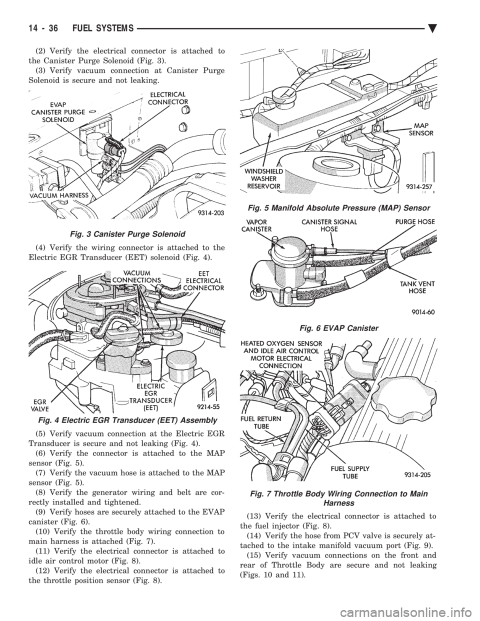
(2) Verify the electrical connector is attached to
the Canister Purge Solenoid (Fig. 3). (3) Verify vacuum connection at Canister Purge
Solenoid is secure and not leaking.
(4) Verify the wiring connector is attached to the
Electric EGR Transducer (EET) solenoid (Fig. 4).
(5) Verify vacuum connection at the Electric EGR
Transducer is secure and not leaking (Fig. 4). (6) Verify the connector is attached to the MAP
sensor (Fig. 5). (7) Verify the vacuum hose is attached to the MAP
sensor (Fig. 5). (8) Verify the generator wiring and belt are cor-
rectly installed and tightened. (9) Verify hoses are securely attached to the EVAP
canister (Fig. 6). (10) Verify the throttle body wiring connection to
main harness is attached (Fig. 7). (11) Verify the electrical connector is attached to
idle air control motor (Fig. 8). (12) Verify the electrical connector is attached to
the throttle position sensor (Fig. 8). (13) Verify the electrical connector is attached to
the fuel injector (Fig. 8). (14) Verify the hose from PCV valve is securely at-
tached to the intake manifold vacuum port (Fig. 9). (15) Verify vacuum connections on the front and
rear of Throttle Body are secure and not leaking
(Figs. 10 and 11).
Fig. 3 Canister Purge Solenoid
Fig. 4 Electric EGR Transducer (EET) Assembly
Fig. 5 Manifold Absolute Pressure (MAP) Sensor
Fig. 6 EVAP Canister
Fig. 7 Throttle Body Wiring Connection to Main Harness
14 - 36 FUEL SYSTEMS Ä
Page 1806 of 2438
2.5L FLEXIBLE FUEL MULTI-PORT FUEL INJECTIONÐGENERAL DIAGNOSIS INDEX
page page
Fuel System Diagram ..................... 66 Visual Inspection......................... 66
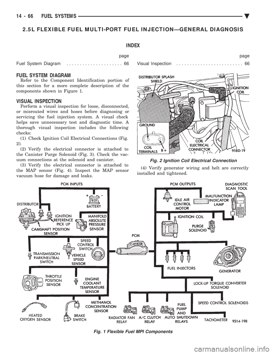
FUEL SYSTEM DIAGRAM
Refer to the Component Identification portion of
this section for a more complete description of the
components shown in Figure 1.
VISUAL INSPECTION
Perform a visual inspection for loose, disconnected,
or misrouted wires and hoses before diagnosing or
servicing the fuel injection system. A visual check
helps save unnecessary test and diagnostic time. A
thorough visual inspection includes the following
checks: (1) Check Ignition Coil Electrical Connections (Fig.
2). (2) Verify the electrical connector is attached to
the Canister Purge Solenoid (Fig. 3). Check the vac-
uum connections at the solenoid and canister. (3) Verify the electrical connector is attached to
the MAP sensor (Fig. 4). Inspect the MAP sensor
vacuum hose for damage and leaks. (4) Verify generator wiring and belt are correctly
installed and tightened.
Fig. 1 Flexible Fuel MPI Components
Fig. 2 Ignition Coil Electrical Connection
14 - 66 FUEL SYSTEMS Ä
Page 1811 of 2438
the PCM to store diagnostic trouble codes for other
systems. For example, a fuel pressure problem will not
register a fault directly, but could cause a rich or lean
condition. This could cause the PCM to store an oxygen
sensor diagnostic trouble code. Fuel Pressure - The vacuum assisted fuel pressure
regulator controls fuel system pressure. The PCM
cannot detect a clogged fuel pump inlet filter, clogged
in-line fuel filter, stuck open regulator, or a pinched
fuel supply or return line. However, these could result
in a rich or lean condition causing the PCM to store an
oxygen sensor diagnostic trouble code. Secondary Ignition Circuit - The PCM cannot
detect an inoperative ignition coil, fouled or worn spark
plugs, ignition cross firing, or open spark plug cables. Engine Timing - The PCM cannot detect an incor-
rectly indexed timing belt, camshaft sprocket and
crankshaft sprocket. However, these could result in a
rich or lean condition causing the PCM to store an
oxygen sensor diagnostic trouble code. Cylinder Compression - The PCM cannot detect
uneven, low, or high engine cylinder compression. Exhaust System - The PCM cannot detect a
plugged, restricted or leaking exhaust system. Fuel Injector Mechanical Malfunctions - The
PCM cannot determine if a fuel injector is clogged, the
needle is sticking or if the wrong injector is installed.
However, these could result in a rich or lean condition
causing the PCM to store an oxygen sensor diagnostic
trouble code. Excessive Oil Consumption - Although the PCM
monitors exhaust stream oxygen content when the
system is in closed loop, it cannot determine excessive
oil consumption. Throttle Body Air Flow - The PCM cannot detect a
clogged or restricted air cleaner inlet or filter element. Evaporative System - The PCM cannot detect a
disconnected (open vacuum line) restricted, plugged or
loaded evaporative purge canister. Vacuum Assist - The PCM cannot detect leaks or
restrictions in the vacuum circuits of vacuum assisted
engine control system devices. However, these could
cause the PCM to store a MAP sensor diagnostic
trouble code and cause a high idle condition. PCM System Ground - The PCM cannot determine
a poor system ground. However, one or more diagnostic
trouble codes may be generated as a result of this
condition. PCM Connector Engagement - The PCM may not
be able to determine spread or damaged connector
pins. However, it might store diagnostic trouble codes
as a result of spread connector pins.HIGH AND LOW LIMITS
The PCM compares input signal voltages from each
input device with established high and low limits for the
device. If the input voltage is not within limits and other
criteria are met, the PCM stores a diagnostic trouble code
in memory. Other diagnostic trouble code criteria might
include engine RPM limits or input voltages from other
sensors or switches that must be present before verifying
a diagnostic trouble code condition.
DIAGNOSTIC TROUBLE CODES
A diagnostic trouble code indicates the powertrain
control module (PCM) has recognized an abnormal
condition in the system. Abnormal conditions are usu-
ally shorted or open circuits.
The technician can display diagnostic trouble codes in
two ways. The first way is to cycle the ignition switch and
count the number of times the malfunction indicator lamp
(check engine lamp on the instrument panel) flashes on
and off. The DRBII scan tool provides the second method
of displaying diagnostic trouble codes. Diagnostic trouble
codes indicate the results of a circuit failure, but do not
directly identify the failed component.
For a list of Diagnostic Trouble Codes, refer to
the charts at the end of this section.
OBTAINING DIAGNOSTIC TROUBLE CODES
USING DRBII SCAN TOOL
WARNING: APPLY PARKING BRAKE AND/OR BLOCK
WHEELS BEFORE PERFORMING ANY TEST ON AN
OPERATING ENGINE. (1) Connect DRBII scan tool to the data link (diag-
nostic) connector located in the engine compartment,
next to the PCM (Fig. 1). (2) If possible, start the engine and cycle the A/C
switch if applicable. Shut off the engine. (3)
Turn the ignition switch on, access Read Fault
Screen. Record all the diagnostic trouble codes shown on
the DRBII scan tool. [Observe the malfunction indicator
lamp (check engine lamp) on the instrument panel. The
lamp should light for 2 seconds then go out (bulb check)].
To erase diagnostic trouble codes, use the Erase
Trouble Code data screen on the DRBII scan tool.
USING THE MALFUNCTION INDICATOR LAMP (1) Cycle the ignition key On - Off - On - Off - On
within 5 seconds. (2) Count the number of times the malfunction indi-
cator lamp (check engine lamp on the instrument
panel) flashes on and off. The number of flashes
represents the trouble code. There is a slight pause be-
Ä FUEL SYSTEMS 14 - 71
Page 1836 of 2438
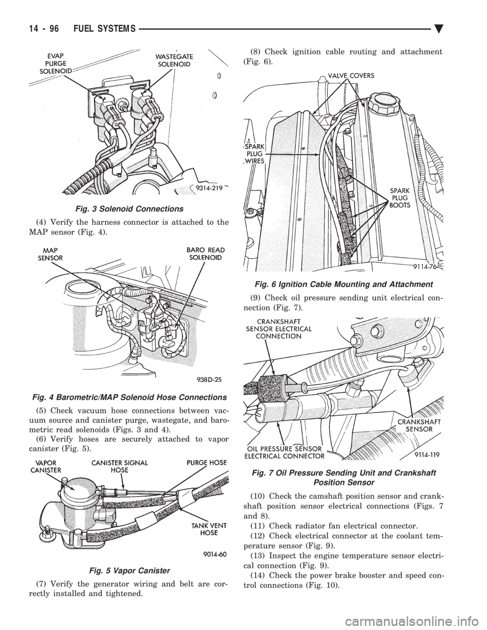
(4) Verify the harness connector is attached to the
MAP sensor (Fig. 4).
(5) Check vacuum hose connections between vac-
uum source and canister purge, wastegate, and baro-
metric read solenoids (Figs. 3 and 4). (6) Verify hoses are securely attached to vapor
canister (Fig. 5).
(7) Verify the generator wiring and belt are cor-
rectly installed and tightened. (8) Check ignition cable routing and attachment
(Fig. 6).
(9) Check oil pressure sending unit electrical con-
nection (Fig. 7).
(10) Check the camshaft position sensor and crank-
shaft position sensor electrical connections (Figs. 7
and 8). (11) Check radiator fan electrical connector.
(12) Check electrical connector at the coolant tem-
perature sensor (Fig. 9). (13) Inspect the engine temperature sensor electri-
cal connection (Fig. 9). (14) Check the power brake booster and speed con-
trol connections (Fig. 10).
Fig. 6 Ignition Cable Mounting and Attachment
Fig. 7 Oil Pressure Sending Unit and Crankshaft Position Sensor
Fig. 3 Solenoid Connections
Fig. 4 Barometric/MAP Solenoid Hose Connections
Fig. 5 Vapor Canister
14 - 96 FUEL SYSTEMS Ä