1993 CHEVROLET PLYMOUTH ACCLAIM belt
[x] Cancel search: beltPage 1943 of 2438
POWER STEERING GEAR INDEX
page page
General Information ....................... 25
Outer Tie Rod ........................... 27 Steering Gear Service
..................... 25
GENERAL INFORMATION
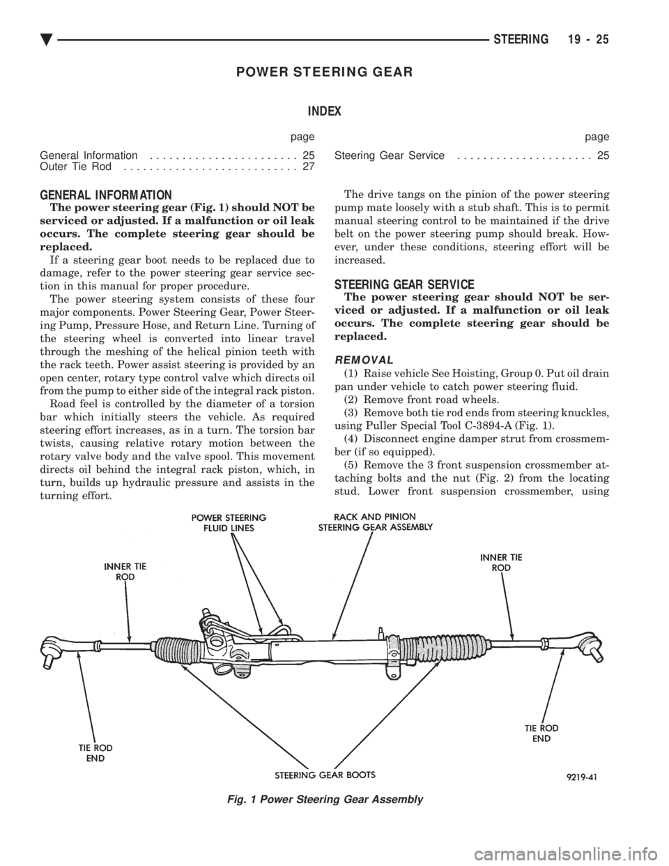
The power steering gear (Fig. 1) should NOT be
serviced or adjusted. If a malfunction or oil leak
occurs. The complete steering gear should be
replaced. If a steering gear boot needs to be replaced due to
damage, refer to the power steering gear service sec-
tion in this manual for proper procedure. The power steering system consists of these four
major components. Power Steering Gear, Power Steer-
ing Pump, Pressure Hose, and Return Line. Turning of
the steering wheel is converted into linear travel
through the meshing of the helical pinion teeth with
the rack teeth. Power assist steering is provided by an
open center, rotary type control valve which directs oil
from the pump to either side of the integral rack piston. Road feel is controlled by the diameter of a torsion
bar which initially steers the vehicle. As required
steering effort increases, as in a turn. The torsion bar
twists, causing relative rotary motion between the
rotary valve body and the valve spool. This movement
directs oil behind the integral rack piston, which, in
turn, builds up hydraulic pressure and assists in the
turning effort. The drive tangs on the pinion of the power steering
pump mate loosely with a stub shaft. This is to permit
manual steering control to be maintained if the drive
belt on the power steering pump should break. How-
ever, under these conditions, steering effort will be
increased.
STEERING GEAR SERVICE
The power steering gear should NOT be ser-
viced or adjusted. If a malfunction or oil leak
occurs. The complete steering gear should be
replaced.
REMOVAL
(1) Raise vehicle See Hoisting, Group 0. Put oil drain
pan under vehicle to catch power steering fluid. (2) Remove front road wheels.
(3) Remove both tie rod ends from steering knuckles,
using Puller Special Tool C-3894-A (Fig. 1). (4) Disconnect engine damper strut from crossmem-
ber (if so equipped). (5) Remove the 3 front suspension crossmember at-
taching bolts and the nut (Fig. 2) from the locating
stud. Lower front suspension crossmember, using
Fig. 1 Power Steering Gear Assembly
Ä STEERING 19 - 25
Page 2167 of 2438
AA-VEHICLE BODY COMPONENT SERVICE INDEX
page page
A-Pillar and Roof Rail Mouldings ............. 25
B-Pillar Trim Panel ....................... 25
Body Side Moulding and Applique ............ 24
Cowl Cover ............................. 13
Cowl Panel Trim and Scuff Plates ............ 25
Door Opening Weatherstrips ................ 24
Floor Carpet ............................ 30
Front Center Console ..................... 29
Front Door and Hinge ..................... 15
Front Door Belt Moulding and Weatherstrip ..... 17
Front Door Glass ........................ 17
Front Door Glass Channel and Run Weatherstrip . 18
Front Door Glass Run Lower Channel ......... 18
Front Door Latch ......................... 16
Front Door Side View Mirror ................ 17
Front Door Silencer and Water Shield ......... 15
Front Door Trim Panel .................... 14
Front Door Window Regulator/Manual ......... 18
Front Door Window Regulator/Power .......... 19
Front End Splash Shields .................. 13
Front Fender ............................ 14
Front Power Door Lock Actuator ............. 19
Front Seat Belts ......................... 27
Front Seats ............................. 28
Fuel Fill Door ........................... 36
Grille .................................. 11
Head Lining ............................. 30
Hood and Hinges ........................ 11
Hood Latch and Release Cable .............. 12
Outside Front Door Latch Release Handle ..... 16
Outside Rear Door Latch Release Handle ...... 21 Overhead Console
........................ 30
Quarter Extension Trim Panel ............... 27
Quarter Trim Panel ....................... 27
Rear Deck Filler Panel .................... 31
Rear Door and Hinge ..................... 20
Rear Door Belt Moulding and Weatherstrip ..... 22
Rear Door Glass ......................... 22
Rear Door Glass Run Weatherstrip ........... 22
Rear Door Glass Stationary Glass Module ..... 23
Rear Door Latch ......................... 21
Rear Door Silencer and Water Shield ......... 20
Rear Door Trim Panel ..................... 20
Rear Door Window Regulator/Manual ......... 23
Rear Door Window Regulator/Power .......... 23
Rear Power Door Lock Actuator ............. 22
Rear Seat Belts .......................... 28
Rear Seats ............................. 28
Rear Shelf Trim Panel ..................... 27
Rear Window Glass ...................... 32
Sun Roof Air Deflector .................... 31
Sun Roof Drain Tubes .................... 31
Sun Roof Weatherstrip .................... 31
Trunk Lid .............................. 33
Trunk Lid Hinge ......................... 34
Trunk Lid Latch .......................... 34
Trunk Lid Lock .......................... 34
Trunk Lid Luggage Rack ................... 35
Trunk Lid Torsion Bar ..................... 34
Trunk Lining ............................ 35
Trunk Opening Weatherstrip ................ 35
Vinyl Roof Bonnet ........................ 31
GRILLE
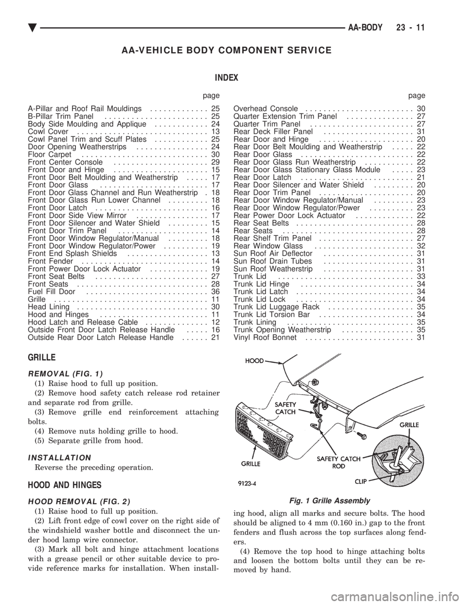
REMOVAL (FIG. 1)
(1) Raise hood to full up position.
(2) Remove hood safety catch release rod retainer
and separate rod from grille. (3) Remove grille end reinforcement attaching
bolts. (4) Remove nuts holding grille to hood.
(5) Separate grille from hood.
INSTALLATION
Reverse the preceding operation.
HOOD AND HINGES
HOOD REMOVAL (FIG. 2)
(1) Raise hood to full up position.
(2) Lift front edge of cowl cover on the right side of
the windshield washer bottle and disconnect the un-
der hood lamp wire connector. (3) Mark all bolt and hinge attachment locations
with a grease pencil or other suitable device to pro-
vide reference marks for installation. When install- ing hood, align all marks and secure bolts. The hood
should be aligned to 4 mm (0.160 in.) gap to the front
fenders and flush across the top surfaces along fend-
ers. (4) Remove the top hood to hinge attaching bolts
and loosen the bottom bolts until they can be re-
moved by hand.
Fig. 1 Grille Assembly
Ä AA-BODY 23 - 11
Page 2169 of 2438
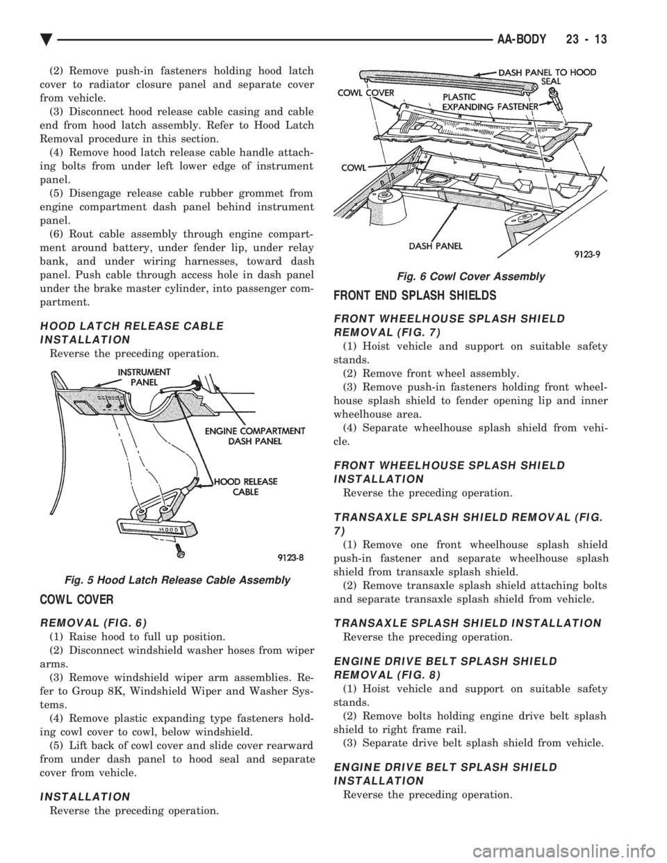
(2) Remove push-in fasteners holding hood latch
cover to radiator closure panel and separate cover
from vehicle. (3) Disconnect hood release cable casing and cable
end from hood latch assembly. Refer to Hood Latch
Removal procedure in this section. (4) Remove hood latch release cable handle attach-
ing bolts from under left lower edge of instrument
panel. (5) Disengage release cable rubber grommet from
engine compartment dash panel behind instrument
panel. (6) Rout cable assembly through engine compart-
ment around battery, under fender lip, under relay
bank, and under wiring harnesses, toward dash
panel. Push cable through access hole in dash panel
under the brake master cylinder, into passenger com-
partment.
HOOD LATCH RELEASE CABLE INSTALLATION
Reverse the preceding operation.
COWL COVER
REMOVAL (FIG. 6)
(1) Raise hood to full up position.
(2) Disconnect windshield washer hoses from wiper
arms. (3) Remove windshield wiper arm assemblies. Re-
fer to Group 8K, Windshield Wiper and Washer Sys-
tems. (4) Remove plastic expanding type fasteners hold-
ing cowl cover to cowl, below windshield. (5) Lift back of cowl cover and slide cover rearward
from under dash panel to hood seal and separate
cover from vehicle.
INSTALLATION
Reverse the preceding operation.
FRONT END SPLASH SHIELDS
FRONT WHEELHOUSE SPLASH SHIELD REMOVAL (FIG. 7)
(1) Hoist vehicle and support on suitable safety
stands. (2) Remove front wheel assembly.
(3) Remove push-in fasteners holding front wheel-
house splash shield to fender opening lip and inner
wheelhouse area. (4) Separate wheelhouse splash shield from vehi-
cle.
FRONT WHEELHOUSE SPLASH SHIELD INSTALLATION
Reverse the preceding operation.
TRANSAXLE SPLASH SHIELD REMOVAL (FIG.7)
(1) Remove one front wheelhouse splash shield
push-in fastener and separate wheelhouse splash
shield from transaxle splash shield. (2) Remove transaxle splash shield attaching bolts
and separate transaxle splash shield from vehicle.
TRANSAXLE SPLASH SHIELD INSTALLATION
Reverse the preceding operation.
ENGINE DRIVE BELT SPLASH SHIELD REMOVAL (FIG. 8)
(1) Hoist vehicle and support on suitable safety
stands. (2) Remove bolts holding engine drive belt splash
shield to right frame rail. (3) Separate drive belt splash shield from vehicle.
ENGINE DRIVE BELT SPLASH SHIELDINSTALLATION
Reverse the preceding operation.
Fig. 5 Hood Latch Release Cable Assembly
Fig. 6 Cowl Cover Assembly
Ä AA-BODY 23 - 13
Page 2170 of 2438
FRONT FENDER
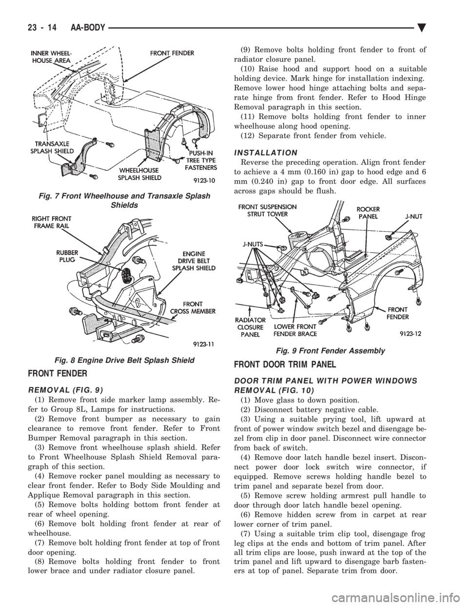
REMOVAL (FIG. 9)
(1) Remove front side marker lamp assembly. Re-
fer to Group 8L, Lamps for instructions. (2) Remove front bumper as necessary to gain
clearance to remove front fender. Refer to Front
Bumper Removal paragraph in this section. (3) Remove front wheelhouse splash shield. Refer
to Front Wheelhouse Splash Shield Removal para-
graph of this section. (4) Remove rocker panel moulding as necessary to
clear front fender. Refer to Body Side Moulding and
Applique Removal paragraph in this section. (5) Remove bolts holding bottom front fender at
rear of wheel opening. (6) Remove bolt holding front fender at rear of
wheelhouse. (7) Remove bolt holding front fender at top of front
door opening. (8) Remove bolts holding front fender to front
lower brace and under radiator closure panel. (9) Remove bolts holding front fender to front of
radiator closure panel. (10) Raise hood and support hood on a suitable
holding device. Mark hinge for installation indexing.
Remove lower hood hinge attaching bolts and sepa-
rate hinge from front fender. Refer to Hood Hinge
Removal paragraph in this section. (11) Remove bolts holding front fender to inner
wheelhouse along hood opening. (12) Separate front fender from vehicle.
INSTALLATION
Reverse the preceding operation. Align front fender
to achiev ea4mm (0.160 in) gap to hood edge and 6
mm (0.240 in) gap to front door edge. All surfaces
across gaps should be flush.
FRONT DOOR TRIM PANEL
DOOR TRIM PANEL WITH POWER WINDOWS REMOVAL (FIG. 10)
(1) Move glass to down position.
(2) Disconnect battery negative cable.
(3) Using a suitable prying tool, lift upward at
front of power window switch bezel and disengage be-
zel from clip in door panel. Disconnect wire connector
from back of switch. (4) Remove door latch handle bezel insert. Discon-
nect power door lock switch wire connector, if
equipped. Remove screws holding handle bezel to
trim panel and separate bezel from door. (5) Remove screw holding armrest pull handle to
door through door latch handle bezel opening. (6) Remove hidden screw from in carpet at rear
lower corner of trim panel. (7) Using a suitable trim clip tool, disengage frog
leg clips at the ends and bottom of trim panel. After
all trim clips are loose, push inward at the top of the
trim panel and lift upward to disengage barb fasten-
ers at top of panel. Separate trim from door.
Fig. 7 Front Wheelhouse and Transaxle Splash Shields
Fig. 8 Engine Drive Belt Splash Shield
Fig. 9 Front Fender Assembly
23 - 14 AA-BODY Ä
Page 2173 of 2438
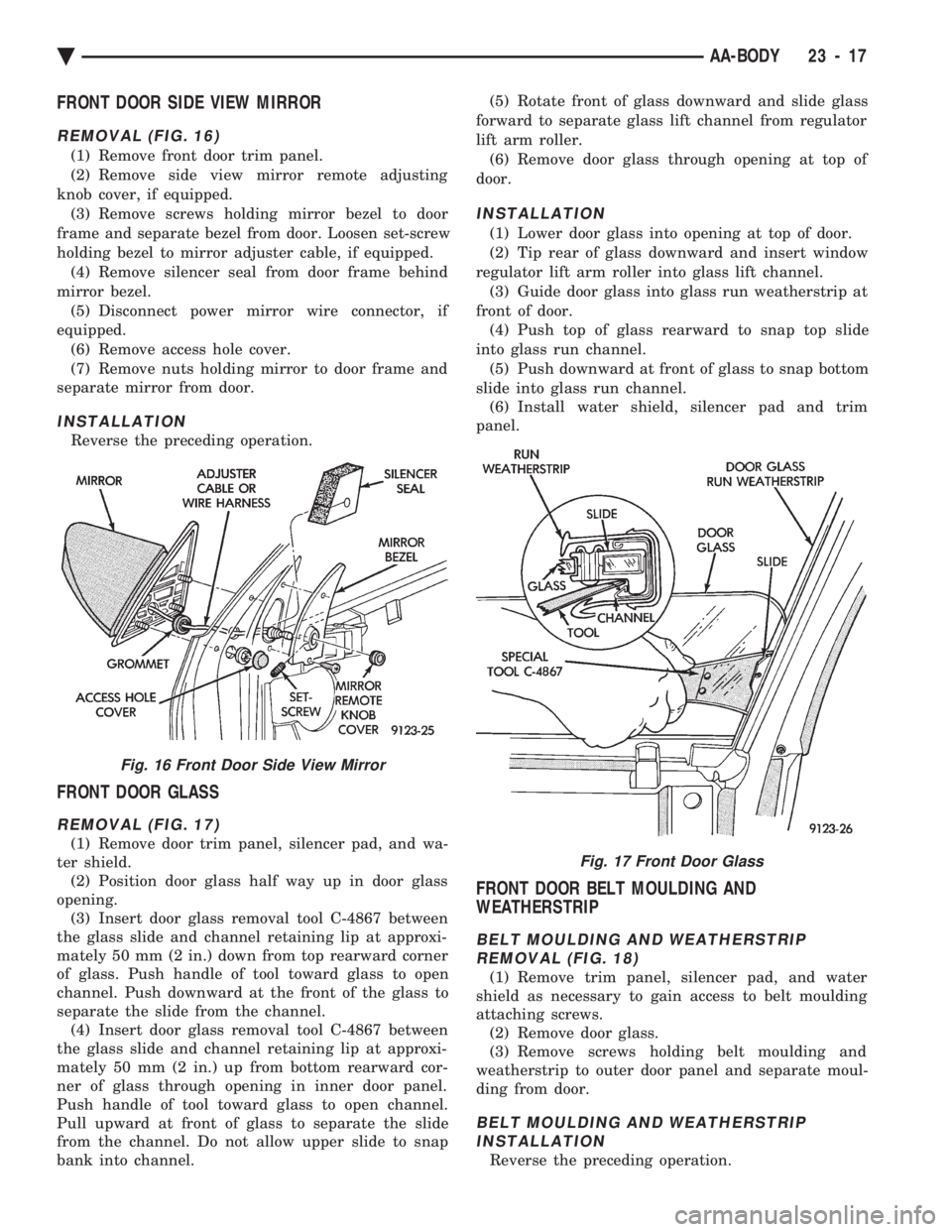
FRONT DOOR SIDE VIEW MIRROR
REMOVAL (FIG. 16)
(1) Remove front door trim panel.
(2) Remove side view mirror remote adjusting
knob cover, if equipped. (3) Remove screws holding mirror bezel to door
frame and separate bezel from door. Loosen set-screw
holding bezel to mirror adjuster cable, if equipped. (4) Remove silencer seal from door frame behind
mirror bezel. (5) Disconnect power mirror wire connector, if
equipped. (6) Remove access hole cover.
(7) Remove nuts holding mirror to door frame and
separate mirror from door.
INSTALLATION
Reverse the preceding operation.
FRONT DOOR GLASS
REMOVAL (FIG. 17)
(1) Remove door trim panel, silencer pad, and wa-
ter shield. (2) Position door glass half way up in door glass
opening. (3) Insert door glass removal tool C-4867 between
the glass slide and channel retaining lip at approxi-
mately 50 mm (2 in.) down from top rearward corner
of glass. Push handle of tool toward glass to open
channel. Push downward at the front of the glass to
separate the slide from the channel. (4) Insert door glass removal tool C-4867 between
the glass slide and channel retaining lip at approxi-
mately 50 mm (2 in.) up from bottom rearward cor-
ner of glass through opening in inner door panel.
Push handle of tool toward glass to open channel.
Pull upward at front of glass to separate the slide
from the channel. Do not allow upper slide to snap
bank into channel. (5) Rotate front of glass downward and slide glass
forward to separate glass lift channel from regulator
lift arm roller. (6) Remove door glass through opening at top of
door.
INSTALLATION
(1) Lower door glass into opening at top of door.
(2) Tip rear of glass downward and insert window
regulator lift arm roller into glass lift channel. (3) Guide door glass into glass run weatherstrip at
front of door. (4) Push top of glass rearward to snap top slide
into glass run channel. (5) Push downward at front of glass to snap bottom
slide into glass run channel. (6) Install water shield, silencer pad and trim
panel.
FRONT DOOR BELT MOULDING AND
WEATHERSTRIP
BELT MOULDING AND WEATHERSTRIP REMOVAL (FIG. 18)
(1) Remove trim panel, silencer pad, and water
shield as necessary to gain access to belt moulding
attaching screws. (2) Remove door glass.
(3) Remove screws holding belt moulding and
weatherstrip to outer door panel and separate moul-
ding from door.
BELT MOULDING AND WEATHERSTRIP INSTALLATION
Reverse the preceding operation.
Fig. 16 Front Door Side View Mirror
Fig. 17 Front Door Glass
Ä AA-BODY 23 - 17
Page 2174 of 2438
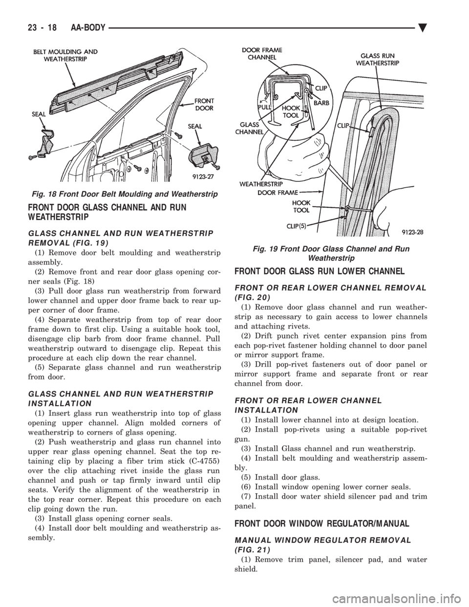
FRONT DOOR GLASS CHANNEL AND RUN
WEATHERSTRIP
GLASS CHANNEL AND RUN WEATHERSTRIP
REMOVAL (FIG. 19)
(1) Remove door belt moulding and weatherstrip
assembly. (2) Remove front and rear door glass opening cor-
ner seals (Fig. 18) (3) Pull door glass run weatherstrip from forward
lower channel and upper door frame back to rear up-
per corner of door frame. (4) Separate weatherstrip from top of rear door
frame down to first clip. Using a suitable hook tool,
disengage clip barb from door frame channel. Pull
weatherstrip outward to disengage clip. Repeat this
procedure at each clip down the rear channel. (5) Separate glass channel and run weatherstrip
from door.
GLASS CHANNEL AND RUN WEATHERSTRIP INSTALLATION
(1) Insert glass run weatherstrip into top of glass
opening upper channel. Align molded corners of
weatherstrip to corners of glass opening. (2) Push weatherstrip and glass run channel into
upper rear glass opening channel. Seat the top re-
taining clip by placing a fiber trim stick (C-4755)
over the clip attaching rivet inside the glass run
channel and push or tap firmly inward until clip
seats. Verify the alignment of the weatherstrip in
the top rear corner. Repeat this procedure on each
clip going down the run. (3) Install glass opening corner seals.
(4) Install door belt moulding and weatherstrip as-
sembly.
FRONT DOOR GLASS RUN LOWER CHANNEL
FRONT OR REAR LOWER CHANNEL REMOVAL (FIG. 20)
(1) Remove door glass channel and run weather-
strip as necessary to gain access to lower channels
and attaching rivets. (2) Drift punch rivet center expansion pins from
each pop-rivet fastener holding channel to door panel
or mirror support frame. (3) Drill pop-rivet fasteners out of door panel or
mirror support frame and separate front or rear
channel from door.
FRONT OR REAR LOWER CHANNEL INSTALLATION
(1) Install lower channel into at design location.
(2) Install pop-rivets using a suitable pop-rivet
gun. (3) Install Glass channel and run weatherstrip.
(4) Install belt moulding and weatherstrip assem-
bly. (5) Install door glass.
(6) Install window opening lower corner seals.
(7) Install door water shield silencer pad and trim
panel.
FRONT DOOR WINDOW REGULATOR/MANUAL
MANUAL WINDOW REGULATOR REMOVAL (FIG. 21)
(1) Remove trim panel, silencer pad, and water
shield.
Fig. 18 Front Door Belt Moulding and Weatherstrip
Fig. 19 Front Door Glass Channel and Run Weatherstrip
23 - 18 AA-BODY Ä
Page 2178 of 2438
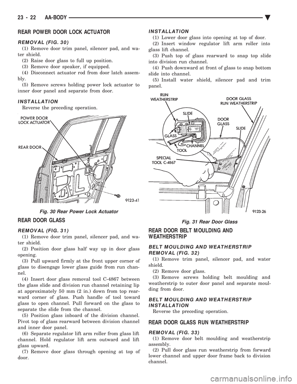
REAR POWER DOOR LOCK ACTUATOR
REMOVAL (FIG. 30)
(1) Remove door trim panel, silencer pad, and wa-
ter shield. (2) Raise door glass to full up position.
(3) Remove door speaker, if equipped.
(4) Disconnect actuator rod from door latch assem-
bly. (5) Remove screws holding power lock actuator to
inner door panel and separate from door.
INSTALLATION
Reverse the preceding operation.
REAR DOOR GLASS
REMOVAL (FIG. 31)
(1) Remove door trim panel, silencer pad, and wa-
ter shield. (2) Position door glass half way up in door glass
opening. (3) Pull upward firmly at the front upper corner of
glass to disengage lower glass guide from run chan-
nel. (4) Insert door glass removal tool C-4867 between
the glass slide and division run channel retaining lip
at approximately 50 mm (2 in.) down from top rear-
ward corner of glass. Push handle of tool toward
glass to open channel. Pull forward on the glass to
separate the slide from the channel. (5) Position glass inboard of the division channel.
Pivot top of glass rearward between division channel
and inner door panel. (6) Separate regulator lift arm roller from glass lift
channel. Hold regulator lift arm outward and lift
glass upward. (7) Remove door glass through opening at top of
door.
INSTALLATION
(1) Lower door glass into opening at top of door.
(2) Insert window regulator lift arm roller into
glass lift channel. (3) Push top of glass rearward to snap top slide
into division run channel. (4) Push downward at front of glass to snap bottom
slide into channel. (5) Install water shield, silencer pad and trim
panel.
REAR DOOR BELT MOULDING AND
WEATHERSTRIP
BELT MOULDING AND WEATHERSTRIP
REMOVAL (FIG. 32)
(1) Remove trim panel, silencer pad, and water
shield. (2) Remove door glass.
(3) Remove screws holding belt moulding and
weatherstrip to outer door panel and separate moul-
ding from door.
BELT MOULDING AND WEATHERSTRIP INSTALLATION
Reverse the preceding operation.
REAR DOOR GLASS RUN WEATHERSTRIP
REMOVAL (FIG. 33)
(1) Remove door belt moulding and weatherstrip
assembly. (2) Pull door glass run weatherstrip from forward
lower channel and upper door frame back to division
channel.
Fig. 30 Rear Power Lock Actuator
Fig. 31 Rear Door Glass
23 - 22 AA-BODY Ä
Page 2179 of 2438
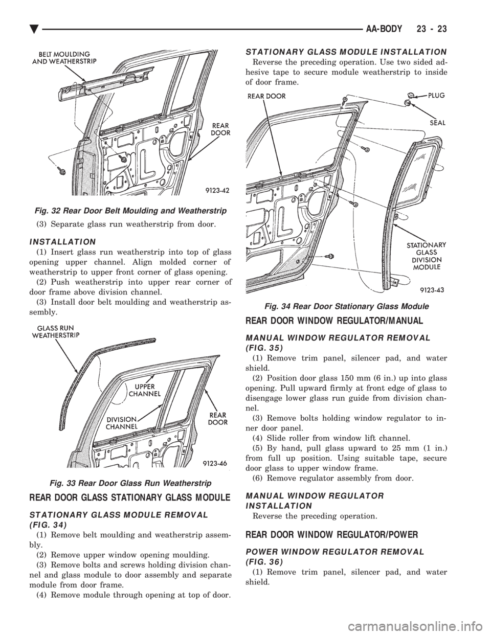
(3) Separate glass run weatherstrip from door.
INSTALLATION
(1) Insert glass run weatherstrip into top of glass
opening upper channel. Align molded corner of
weatherstrip to upper front corner of glass opening. (2) Push weatherstrip into upper rear corner of
door frame above division channel. (3) Install door belt moulding and weatherstrip as-
sembly.
REAR DOOR GLASS STATIONARY GLASS MODULE
STATIONARY GLASS MODULE REMOVAL (FIG. 34)
(1) Remove belt moulding and weatherstrip assem-
bly. (2) Remove upper window opening moulding.
(3) Remove bolts and screws holding division chan-
nel and glass module to door assembly and separate
module from door frame. (4) Remove module through opening at top of door.
STATIONARY GLASS MODULE INSTALLATION
Reverse the preceding operation. Use two sided ad-
hesive tape to secure module weatherstrip to inside
of door frame.
REAR DOOR WINDOW REGULATOR/MANUAL
MANUAL WINDOW REGULATOR REMOVAL (FIG. 35)
(1) Remove trim panel, silencer pad, and water
shield. (2) Position door glass 150 mm (6 in.) up into glass
opening. Pull upward firmly at front edge of glass to
disengage lower glass run guide from division chan-
nel. (3) Remove bolts holding window regulator to in-
ner door panel. (4) Slide roller from window lift channel.
(5) By hand, pull glass upward to 25 mm (1 in.)
from full up position. Using suitable tape, secure
door glass to upper window frame. (6) Remove regulator assembly from door.
MANUAL WINDOW REGULATORINSTALLATION
Reverse the preceding operation.
REAR DOOR WINDOW REGULATOR/POWER
POWER WINDOW REGULATOR REMOVAL(FIG. 36)
(1) Remove trim panel, silencer pad, and water
shield.
Fig. 32 Rear Door Belt Moulding and Weatherstrip
Fig. 33 Rear Door Glass Run Weatherstrip
Fig. 34 Rear Door Stationary Glass Module
Ä AA-BODY 23 - 23