1993 CHEVROLET PLYMOUTH ACCLAIM belt
[x] Cancel search: beltPage 1576 of 2438
shaft end play. A sintered iron (TBI engine and steel
billet Turbo III engines) timing belt sprocket is
mounted on the cam nose, and a hydrodynamic oil
seal is used for oil control at the front of the cam-
shaft. ACCESSORY SHAFT: The iron accessory shaft
has two bearing journals and is housed in the for-
ward facing side of the block. A hydrodynamic seal,
installed in an aluminum housing attached to the
block, provides retention, shaft thrust, and oil con-
trol. The accessory shaft is driven by the timing belt
through a sintered iron (TBI engine and steel billet
Turbo III engines) sprocket mounted on the nose of
the accessory shaft. The accessory shaft in turn
drives the oil pump and distributor on 2.2/2.5L and
2.5L FFV and the oil pump only on Turbo III. VALVES: The valves are actuated by roller cam
followers which pivot on stationary hydraulic lash
adjusters. The valve train with 40.6 mm (1.60 inch)
diameter intake valves and 35.4 mm (1.39 inch) di-
ameter exhaust valves employ viton rubber valve
stem seals except 2.5L FFv . the 2.5L FFV valve
stem seals are made of special rubber compound
which resist the deteriorating effects of methanol
fuel by-products that enter the oil during combus-
tion. Valve springs, spring retainers, and locks are
conventional. For Turbo III engines the valves are
actuated by roller tipped rocker arms with hydraulic
lash adjusters which pivot on a shaft. The valve train
with 33.88 mm (1.33 in.) diameter intake valves are
arranged in line opposite of the 29.26 mm (1.15 in.)
diameter exhaust valves employ locking valve stem
seals. Valve springs, spring retainers, and locks are
not interchangeable with other engines. BALANCE SHAFTS: 2.2 Turbo III and 2.5L en-
gines are equipped with two counter rotating balance
shafts installed in a carrier attached to the lower
crankcase. The shafts are interconnect through
gears. These gears are driven by a short chain from
the crankshaft, to rotate at two times crankshaft
speed. This counterbalances certain engine recipro-
cating forces. INTAKE MANIFOLDS:
All intake manifolds are
aluminum castings, attached to the cylinder head
with eight bolts. N.A. engines use a four branch de-
sign. This long branch fan design enhances low and
midspeed torque. It also features an integrally cast
water crossover passage to warm incoming fuel/air
mixture, plus an EGR mounting boss and PCV inlet. The Turbo III engine intake manifold is a log type
with tuned runners. The manifold is machined to ac-
cept fuel injectors near the ports of each cylinder. EXHAUST MANIFOLDS: The exhaust manifolds
are made of nodular cast iron for strength and high
temperatures. All naturally aspirated (N.A.) and tur-
bocharged engines exit exhaust gasses through a ma-
chined, articulated joint connection to the exhaust
pipe. 2.2/2.5L and 2.5L FFV manifolds intermesh
with the intake manifold at the cylinder head. N.A. engines use a four branch design with cylin-
ders one and four joined and cylinder two and three
joined to exit at the outlet. The Turbo III engine exhaust manifold also carries
the turbocharger. This manifold has a modified log
type collector with exhaust gasses directed to and
through the turbocharger to exit the conical (articu-
lated joint) outlet machined into the turbocharger ex-
haust elbow. ENGINE LUBRICATION: Refer to Group 0 Lu-
brication and Maintenance for recommended oil to be
used in various engine application. System is full
flow filtration, pressure feed type. The oil pump is
mounted within the crankcase and driven by the ac-
cessory shaft. Pressurized oil is then routed through
the main oil gallery, running the length of the cylin-
der block, supplying main and rod bearings with fur-
ther routing (for 2.2L turbo III and 2.5L engines) to
the lower balance shaft assemblies. Pistons are lubri-
cated from directed holes in the connecting rod as-
semblies. Camshaft and valve mechanisms are
lubricated from a full-length cylinder head oil gallery
supplied from the crankcase main oil gallery.
9 - 10 2.2/2.5L ENGINE Ä
Page 1580 of 2438
CAUTION: Make sure clutch cable has been discon-
nected. (20) Remove front engine mount screw and nut.
(21) Remove manual transmission damper.
(22) Remove left insulator through bolt from inside
wheelhouse or insulator bracket to transmission
screws. (23) Remove engine from vehicle.
INSTALLATION
(1) Install hoist to the engine and lower engine
into the engine compartment. SEE: ENGINE MOUNT RUBBER INSULATORS,
THIS GROUP. (2) Align engine mounts and install but do not
tighten until all mounting bolts have been installed.
(3) Install transmission case to cylinder block
mounting screws. Tighten to 95 N Im (70 ft. lbs.)
torque. (4) Remove engine hoist and transmission holding
fixture. (5) Install ground strap.
(6) Install right inner splash shield.
(7) Connect starter. See Electrical Group 8 for in-
stallation. (8) Connect exhaust system. See Exhaust Systems
Group 11 for installation. (9) Manual Transmission: Install transmission
case lower cover. Automatic Transmission: Remove C clamp from
torque converter housing. Align flexplate to torque
converter and install mounting screws. Tighten to 75
N Im (55 ft. lbs.) torque.
(10) Manual Transmission: Connect clutch cable.
See Clutch Group 6. (11) Install power steering pump. Refer to Cooling
System Group 7, Accessory Drive Section for belt
tension adjustment. (12) Connect fuel line, heater hose, and accelerator
cable. (13) Connect all electrical connections and har-
nesses at throttle body and engine. (14) Install oil filter. Fill engine crankcase with
proper oil to correct level. (15) Install air conditioning compressor (if
equipped). See Heater and Air Conditioning, Group
24 for installation. (16) Install air cleaner and hoses.
(17) Install radiator and shroud assembly . Install
radiator hoses. Fill cooling system. See Cooling Sys-
tem Group 7 for filling procedure. (18) Install hood.
(19) Connect battery.
(20) Start engine and run until operating temper-
ature is reached. (21) Adjust transmission linkage, if necessary.
SOLID MOUNT COMPRESSOR BRACKET SERVICE
When service procedures require solid mount
bracket removal and installation for example: cylin-
der head removal, etc., it is important that bracket
fasteners numbered 1 through 7 (Fig. 4) be removed
and installed in sequence, as instructed in Remove
and Install.
ACCESSORIES REMOVAL
(1) Remove (and install/adjust) belts,see Accessory
Drive Belts in Cooling System,Group 7. (2) Remove air conditioning compressor (in vehicle
with lines and set aside) (Fig. 6). (3) Remove generator pivot bolt and remove gener-
ator (in vehicle: turn wiring side up and disconnect,
then rotate generator, pulley end towards engine and
remove). (4) Remove air conditioner compressor belt idler.
SOLID MOUNT BRACKETÐREMOVAL (FIG. 4)
(1) Remove right engine mount yoke screw (see
Engine Remove Fig. 3) securing engine mount sup-
port strut to engine mount bracket. (2) Remove five side mounting bolts #1, #4 , #5,
#6, and #7 (Fig. 4). (3) Remove front mounting nut, #2, and remove
front bolt #3*. (4) Remove front mounting bolt and strut, rotate
solid mount bracket away from engine and slide
bracket on stud until #2 nut mounting stud until
free. Remove spacer from stud.
SOLID MOUNT BRACKETÐINSTALLATION
(1) Put spacer onto stud, then install bracket on
front (#2 nut) mounting stud and slide bracket over
timing belt cover into position. (2) Loosen assembly bracket to engine fasteners
(numbered #1 through #7 in Fig. 6). (3)
CAUTION: Fasteners MUST BE TIGHTENED IN SE-
QUENCE and to specified torque as follows :
² First Bolt #1 to 3.3 N Im (30 in. lbs.)
² Second Nut #2 and Bolt #3 to 54 N Im (40 ft. lbs.).
² Third Bolts #1 (second tightening) #4 and #5 to
54 N Im (40 ft. lbs.).
² Fourth Bolts #6 and #7 to 54 N Im (40 ft. lbs.).
(4) Install generator and compressor. Tighten com-
pressor mounting bracket bolts to 54 N Im (40 ft.
lbs.).
SOLID MOUNT COMPRESSOR BRACKET SERVICEÐTURBO III ENGINE
REMOVAL
(1) Disconnect negative battery cable
9 - 14 2.2/2.5L ENGINE Ä
Page 1581 of 2438
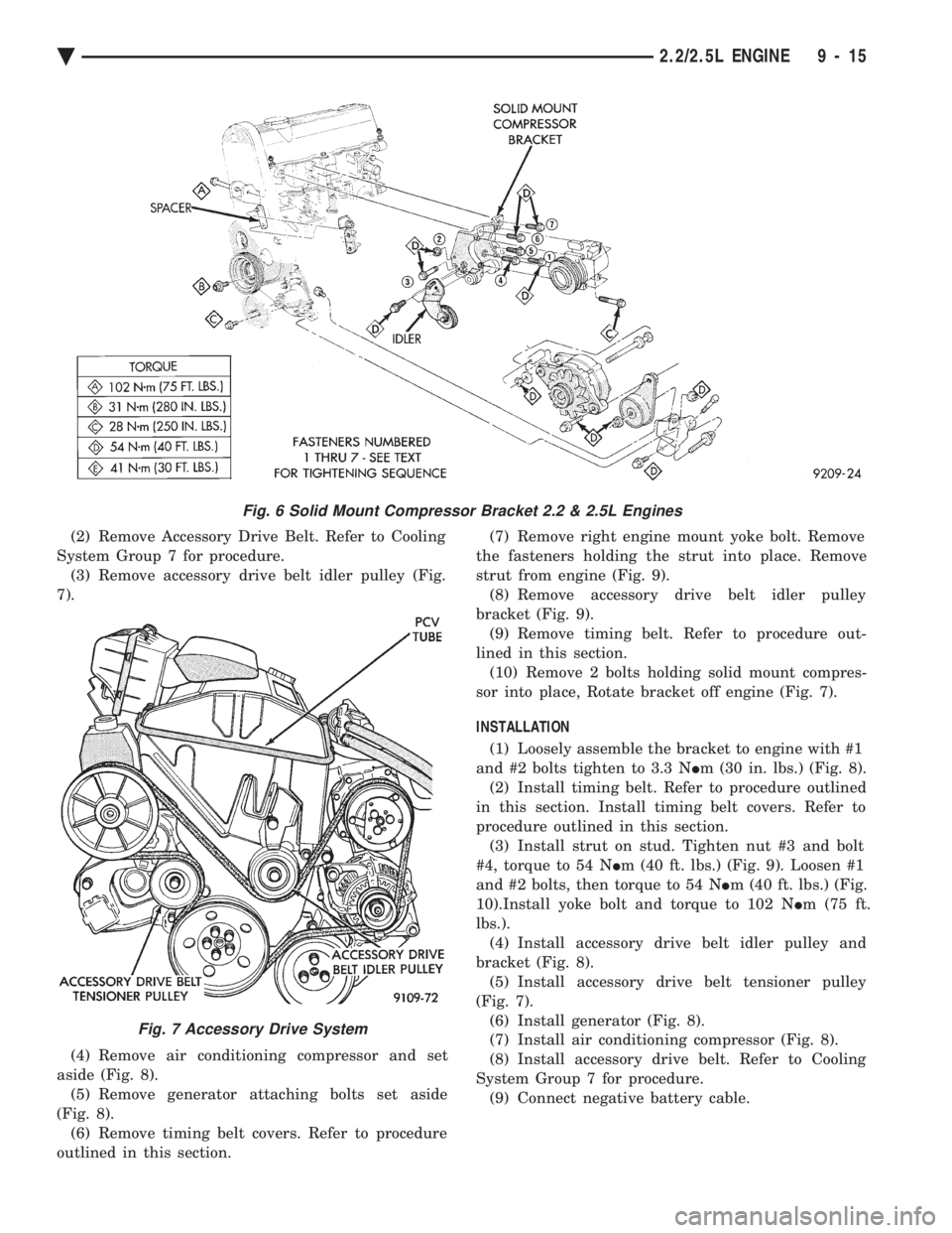
(2) Remove Accessory Drive Belt. Refer to Cooling
System Group 7 for procedure. (3) Remove accessory drive belt idler pulley (Fig.
7).
(4) Remove air conditioning compressor and set
aside (Fig. 8). (5) Remove generator attaching bolts set aside
(Fig. 8). (6) Remove timing belt covers. Refer to procedure
outlined in this section. (7) Remove right engine mount yoke bolt. Remove
the fasteners holding the strut into place. Remove
strut from engine (Fig. 9). (8) Remove accessory drive belt idler pulley
bracket (Fig. 9). (9) Remove timing belt. Refer to procedure out-
lined in this section. (10) Remove 2 bolts holding solid mount compres-
sor into place, Rotate bracket off engine (Fig. 7).
INSTALLATION
(1) Loosely assemble the bracket to engine with #1
and #2 bolts tighten to 3.3 N Im (30 in. lbs.) (Fig. 8).
(2) Install timing belt. Refer to procedure outlined
in this section. Install timing belt covers. Refer to
procedure outlined in this section. (3) Install strut on stud. Tighten nut #3 and bolt
#4, torque to 54 N Im (40 ft. lbs.) (Fig. 9). Loosen #1
and #2 bolts, then torque to 54 N Im (40 ft. lbs.) (Fig.
10).Install yoke bolt and torque to 102 N Im (75 ft.
lbs.). (4) Install accessory drive belt idler pulley and
bracket (Fig. 8). (5) Install accessory drive belt tensioner pulley
(Fig. 7). (6) Install generator (Fig. 8).
(7) Install air conditioning compressor (Fig. 8).
(8) Install accessory drive belt. Refer to Cooling
System Group 7 for procedure. (9) Connect negative battery cable.
Fig. 6 Solid Mount Compressor Bracket 2.2 & 2.5L Engines
Fig. 7 Accessory Drive System
Ä 2.2/2.5L ENGINE 9 - 15
Page 1582 of 2438
POWER STEERING/ACCESSORY DRIVE BELT TENSIONER BRACKET
REMOVAL
(1) Remove Accessory Drive Belt. Refer to Cooling
System Group 7 for procedure. (2) Remove accessory drive belt tensioner pulley
(Fig. 7). (3) Remove Timing Belt covers. Refer to procedure
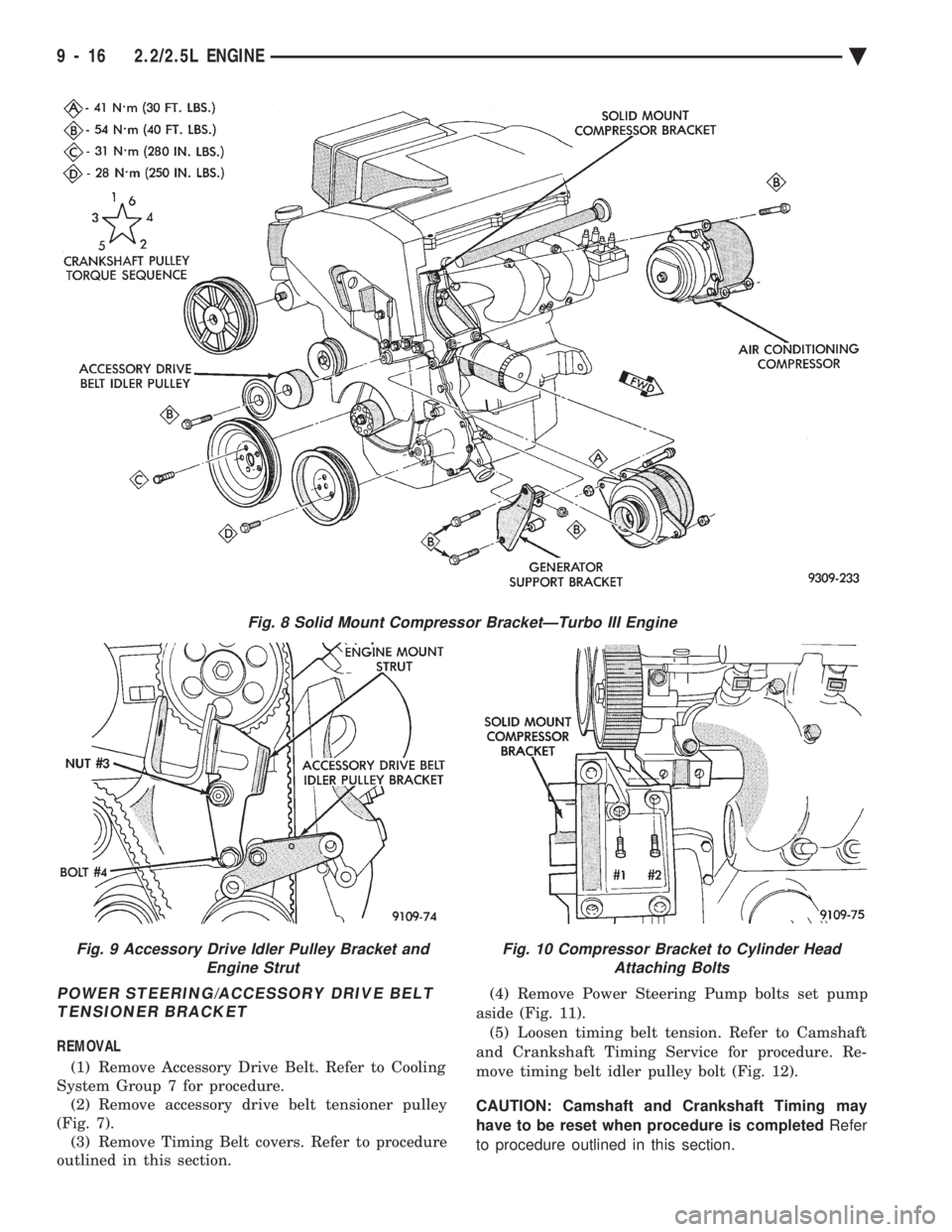
outlined in this section. (4) Remove Power Steering Pump bolts set pump
aside (Fig. 11). (5) Loosen timing belt tension. Refer to Camshaft
and Crankshaft Timing Service for procedure. Re-
move timing belt idler pulley bolt (Fig. 12).
CAUTION: Camshaft and Crankshaft Timing may
have to be reset when procedure is completed Refer
to procedure outlined in this section.
Fig. 8 Solid Mount Compressor BracketÐTurbo III Engine
Fig. 9 Accessory Drive Idler Pulley Bracket and Engine StrutFig. 10 Compressor Bracket to Cylinder HeadAttaching Bolts
9 - 16 2.2/2.5L ENGINE Ä
Page 1583 of 2438
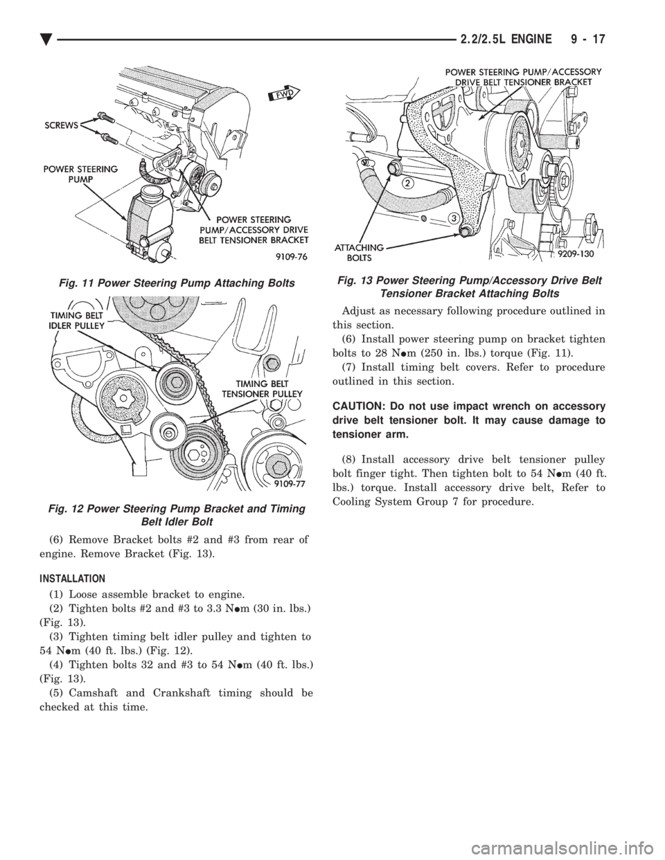
(6) Remove Bracket bolts #2 and #3 from rear of
engine. Remove Bracket (Fig. 13).
INSTALLATION (1) Loose assemble bracket to engine.
(2) Tighten bolts #2 and #3 to 3.3 N Im (30 in. lbs.)
(Fig. 13). (3) Tighten timing belt idler pulley and tighten to
54 N Im (40 ft. lbs.) (Fig. 12).
(4) Tighten bolts 32 and #3 to 54 N Im (40 ft. lbs.)
(Fig. 13). (5) Camshaft and Crankshaft timing should be
checked at this time. Adjust as necessary following procedure outlined in
this section. (6) Install power steering pump on bracket tighten
bolts to 28 N Im (250 in. lbs.) torque (Fig. 11).
(7) Install timing belt covers. Refer to procedure
outlined in this section.
CAUTION: Do not use impact wrench on accessory
drive belt tensioner bolt. It may cause damage to
tensioner arm.
(8) Install accessory drive belt tensioner pulley
bolt finger tight. Then tighten bolt to 54 N Im (40 ft.
lbs.) torque. Install accessory drive belt, Refer to
Cooling System Group 7 for procedure.
Fig. 11 Power Steering Pump Attaching Bolts
Fig. 12 Power Steering Pump Bracket and Timing Belt Idler Bolt
Fig. 13 Power Steering Pump/Accessory Drive BeltTensioner Bracket Attaching Bolts
Ä 2.2/2.5L ENGINE 9 - 17
Page 1584 of 2438
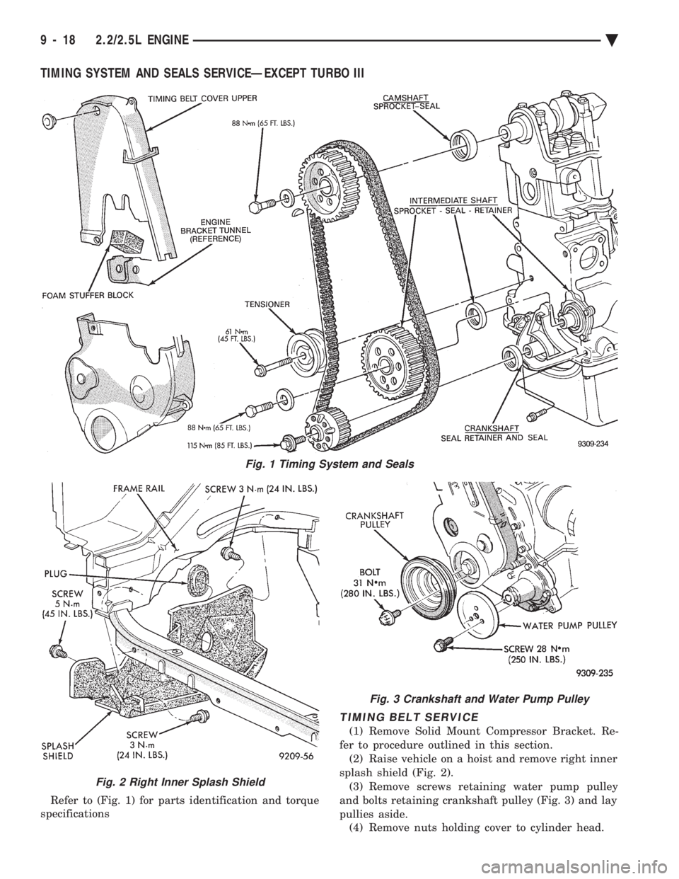
TIMING SYSTEM AND SEALS SERVICEÐEXCEPT TURBO III
Refer to (Fig. 1) for parts identification and torque
specifications
TIMING BELT SERVICE
(1) Remove Solid Mount Compressor Bracket. Re-
fer to procedure outlined in this section. (2) Raise vehicle on a hoist and remove right inner
splash shield (Fig. 2). (3) Remove screws retaining water pump pulley
and bolts retaining crankshaft pulley (Fig. 3) and lay
pullies aside. (4) Remove nuts holding cover to cylinder head.
Fig. 2 Right Inner Splash Shield
Fig. 3 Crankshaft and Water Pump Pulley
Fig. 1 Timing System and Seals
9 - 18 2.2/2.5L ENGINE Ä
Page 1585 of 2438
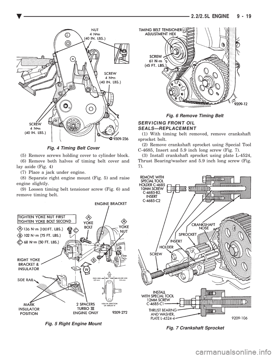
(5) Remove screws holding cover to cylinder block.
(6) Remove both halves of timing belt cover and
lay aside (Fig. 4) (7) Place a jack under engine.
(8) Separate right engine mount (Fig. 5) and raise
engine slightly. (9) Loosen timing belt tensioner screw (Fig. 6) and
remove timing belt.
SERVICING FRONT OIL SEALSÐREPLACEMENT
(1) With timing belt removed, remove crankshaft
sprocket bolt. (2) Remove crankshaft sprocket using Special Tool
C-4685, Insert and 5.9 inch long screw (Fig. 7). (3) Install crankshaft sprocket using plate L-4524,
Thrust Bearing/washer and 5.9 inch long screw (Fig.
7).
Fig. 4 Timing Belt Cover
Fig. 7 Crankshaft SprocketFig. 5 Right Engine Mount
Fig. 6 Remove Timing Belt
Ä 2.2/2.5L ENGINE 9 - 19
Page 1587 of 2438
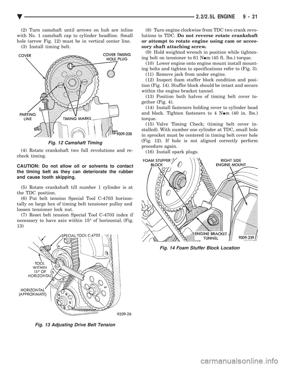
(2) Turn camshaft until arrows on hub are inline
with No. 1 camshaft cap to cylinder headline. Small
hole (arrow Fig. 12) must be in vertical center line. (3) Install timing belt.
(4) Rotate crankshaft two full revolutions and re-
check timing.
CAUTION: Do not allow oil or solvents to contact
the timing belt as they can deteriorate the rubber
and cause tooth skipping.
(5) Rotate crankshaft till number 1 cylinder is at
the TDC position. (6) Put belt tension Special Tool C-4703 horizon-
tally on large hex of timing belt tensioner pulley and
loosen tensioner lock nut. (7) Reset belt tension Special Tool C-4703 index if
necessary to have axis within 15É of horizontal. (Fig.
13) (8) Turn engine clockwise from TDC two crank revo-
lutions to TDC. Do not reverse rotate crankshaft
or attempt to rotate engine using cam or acces-
sory shaft attaching screw. (9) Hold weighted wrench in position while tighten-
ing bolt on tensioner to 61 N Im (45 ft. lbs.) torque.
(10) Lower engine onto engine mount install mount-
ing bolts and tighten to specifications refer to (Fig. 3). (11) Remove jack from under engine.
(12) Inspect foam stuffer block condition and posi-
tion (Fig. 14). Stuffer block should be intact and secure
within the engine bracket tunnel. (13) Position both halves of timing belt cover to-
gether (Fig. 4). (14) Install fasteners holding cover to cylinder head
and block. Tighten fasteners to 4 N Im (40 in. lbs.)
torque. (15) Valve Timing Check; (timing belt cover in-
stalled). With number one cylinder at TDC, small hole
in sprocket must be centered in timing belt cover hole
(Fig. 12). If hole is not aligned correctly perform
procedure again. (16) Install spark plugs.
Fig. 12 Camshaft Timing
Fig. 13 Adjusting Drive Belt Tension
Fig. 14 Foam Stuffer Block Location
Ä 2.2/2.5L ENGINE 9 - 21