1993 CHEVROLET PLYMOUTH ACCLAIM belt
[x] Cancel search: beltPage 592 of 2438

(4) Remove seat cushion.
(5) Remove quarter trim lower extension panel.
(6) Remove front seat belt turning loop and cover.
(7) Remove rear reading lamp.
(8) Remove quarter trim panel.
(9) Remove two seat back latches.
(10) Pull out shelf trim side extension molding.
(11) Remove shelf trim center extension molding.
(12) Remove shelf trim panel (Fig. 26).
(13) Remove four speaker retaining screws.
(14) Lift speaker away from shelf panel and dis-
connect wiring. (15) For installation reverse above procedures. Be
sure to position speakers so that terminals are point-
ing outward.
REAR SPEAKER REPLACEMENTÐAJ BODY WITH FIXED SEAT BACK
(1) Remove seat cushion.
(2) Remove seat back.
(3) Remove quarter trim panels.
(4) Remove shelf trim panel.
(5) Remove four speaker retaining screws (Fig. 26).
(6) Lift speaker away from shelf panel and discon-
nect wiring. (7) For installation reverse above procedures. Be
sure to position speakers so that terminals are point-
ing outward.
REAR SPEAKER REPLACEMENTÐAJ BODY CONVERTIBLE
(1) Move folding top to UP position.
(2) Unsnap sling well from tacking strip and fold-
out of the way to gain access to speaker. (3) Lower folding top to improve speaker accessi-
bility. (4) Remove two speaker retaining screws (Fig. 27).
(5) Disconnect wiring and pull out speaker.
(6) For installation reverse above procedures.
AP Body
DOOR MOUNTED SPEAKER REPLACEMENTÐAP BODY
(1) Remove door trim panel.
(2) Remove two screws holding speaker to inner
door panel (Fig. 28). (3) Pull speaker out and disconnect wiring.
(4) For installation reverse above procedures.
Fig. 25 Door Mounted SpeakerÐAJ Body
Fig. 26 Rear SpeakerÐAJ Body
Fig. 27 Rear SpeakerÐAJ Body
8F - 26 AUDIO SYSTEM Ä
Page 681 of 2438
AA .............................................................................74
Low Fuel
AA ...........................................................................103
AP ............................................................................161
AC, AY...............................................................PC194
AG, AJ ............................................................5269245
Low Washer Fluid
AA, AC, AY .............................................................74
AP ............................................................................161
AG, AJ ............................................................4437661
Oil Pressure
All .......................................................................PC194
Trunk Open
AA, AC, AY .............................................................74
AP ............................................................................161
AG, AJ ............................................................4437661
Theft Alarm Set
AC, AY....................................................................168
AG, AJ ............................................................4437661
Turn Signal (MIC)
AA ...........................................................................103
AC, AG, AJ, AP, AY .......................................PC194
Turn Signal (EIC)
AA, AY ..............................................................PC194
Seat Belt (MIC)
AA ...........................................................................103
AC, AG, AJ, AP, AY .......................................PC194
Seat Belt (EIC)
AA, AY ..............................................................PC194
AJ ............................................................................103
DIMMER CONTROLLED LAMPS
Service procedures for most of the lamps in the in-
strument panel, Instrument cluster and switches are
located in Group 8E, Instrument Panel and Gauges. A/C Heater Control
All ..............................................................................37
Automatic Temperature Control
All ....................................................................4437661
Column Gearshift Indicator
AA, AC, AY ...........................................................161
Console Gearshift Indicator
AP ............................................................................194
AA, AG, AJ ............................................................161
Fog Lamp Switch Symbol
AG ......................................................................PC194
Headlamp Dimmer Switch
AG, AJ ......................................................................37
Headlamp Switch Symbol
AC, AY....................................................................161
AG, AJ ......................................................................37
Heater Control
All ............................................................................158
EVIC
AJ...........................................................................ASC
Instrument Cluster (MIC)
All .......................................................................PC194
Instrument Cluster (EIC) AA, AY .....................................................................74
Message Center
AA, AC, AY .............................................................74
AP ............................................................................161
Navigator/Travel Companion
AA, AJ ......................................................................74
Radio
All ..........................................................................ASC
Rear Defogger Switch
Not Serviceable, Replace Switch
Rear Wiper Switch
AG .............................................................................37
Theft Alarm
AC, AY....................................................................161
Top Lift Switch
AJ ....................................................................5268053
Travel Computer
All ..........................................................................ASC
Turbo Gauge
AP ............................................................................161
Windshield Wiper Switch
AG, AJ ......................................................................37
NON-DIMMING LAMPS
Service procedures for most of the lamps in the fol-
lowing list can be found in Group 23, Body. Some
components have lamps that can only be serviced by
a Authorized Service Center (ASC) after the compo-
nent is removed from the vehicle. Contact local
dealer for location of nearest ASC. Ash Receiver
AA .............................................................................74
AC, AP, AY ............................................................161
AG, AJ ......................................................................37
Center Console Rear
AJ ............................................................................906
Cigar Lighter
AA, AP ....................................................................161
Courtesy
AA, AC, AY-S .....................................................214-2
AJ ............................................................................906
AY-P.....................................................................212-2
Dome
ALL ......................................................................211-2
Engine Compartment
All ............................................................................105
Glove Compartment
All ..........................................................................1891
Ignition Lock
All ..............................................................................37
Inside Rear View Mirror
AJ ............................................................................168
Overhead Console
AA ...........................................................................912
AC, AY....................................................................906
AG, AJ, AP .........................................................212-2
Reading Lamp Front
All ............................................................................906
Ä LAMPS 8L - 39
Page 711 of 2438

wing. Refer to Owner Manual supplied with vehicle
for complete instructions for seat operation.
SWITCH TEST
For switch testing, remove switch from its mount-
ing location. Using an ohmmeter, refer to Figures 13
and 14 to determine if continuity is correct. If these
results are not obtained, replace the switch.
SWITCH REPLACEMENT REMOVAL
(1) Remove left cushion side shield.
(2) Disconnect wiring from switch.
(3) Depress bezel retainers and push switch from
bezel. (4) For installation, reverse above procedure.
POWER MEMORY SEAT, RECLINER AND
MIRRORS
AC & AY Body vehicles have, as an option, a spe-
cial 2 position memory power seat, recliner and
memory power outside rear view mirror system.
Each of the components can be moved to a desired
position by operating switches (Fig. 15). The seat and
recliner use potentiometers as position sensors and
the mirrors use rheostats to send their positioning
information back to the control module in the driv-
er's seat. After the desired seat and mirror position is
set. The seat, recliner, and mirror position can be
memorized at any time by pressing and release the
Set button. Followed by pressing the Position 1 or 2
button, for the specific position desired. DO NOT
press any other seat related switch for at least 5 sec-
onds. However, for the driver to recall a position, the
vehicle must not be moving and the seat belt must
NOT be buckled. Refer to the Owners Manual sup-
plied with the vehicle for complete instructions on
system operation.
Fig. 7 Switch ContinuityÐAG & AJ Bodies (8-Way)
Fig. 8 Seat AdjusterÐAC and AJ Bodies
Ä POWER SEATS 8R - 5
Page 718 of 2438
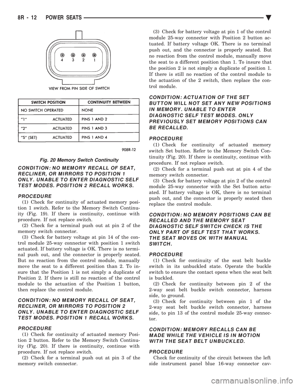
CONDITION: NO MEMORY RECALL OF SEAT, RECLINER, OR MIRRORS TO POSITION 1ONLY. UNABLE TO ENTER DIAGNOSTIC SELFTEST MODES. POSITION 2 RECALL WORKS.
PROCEDURE
(1) Check for continuity of actuated memory posi-
tion 1 switch. Refer to the Memory Switch Continu-
ity (Fig. 19). If there is continuity, continue with
procedure. If not replace switch. (2) Check for a terminal push out at pin 2 of the
memory switch connector. (3) Check for battery voltage at pin 14 of the con-
trol module 25-way connector with position 1 switch
actuated. If battery voltage is OK. There is no termi-
nal push out, and the connector is properly seated.
But no reaction from the control module, manually
move the seat to a different position than 2. To in-
sure that the Position 1 is not simply a duplicate of
Position 2. If there is still no reaction of the control
module to the actuation of the Position 1 button,
then replace the control module.
CONDITION: NO MEMORY RECALL OF SEAT, RECLINER, OR MIRRORS TO POSITION 2ONLY. UNABLE TO ENTER DIAGNOSTIC SELFTEST MODES. POSITION 1 RECALL WORKS.
PROCEDURE
(1) Check for continuity of actuated memory Posi-
tion 2 button. Refer to the Memory Switch Continu-
ity (Fig. 20). If there is continuity, continue with
procedure. If not replace switch. (2) Check for a terminal push out at pin 3 of the
memory switch connector. (3) Check for battery voltage at pin 1 of the control
module 25-way connector with Position 2 button ac-
tuated. If battery voltage OK. There is no terminal
push out, and the connector is properly seated. But
no reaction from the control module, manually move
the seat to a different position than 1. To insure that
the position 2 is not simply a duplicate of position 1.
If there is still no reaction of the control module to
the actuation of the 2 switch, then replace the con-
trol module.
CONDITION: ACTUATION OF THE SET BUTTON WILL NOT SET ANY NEW POSITIONSIN MEMORY. UNABLE TO ENTERDIAGNOSTIC SELF TEST MODES. ONLYPREVIOUSLY SET MEMORY POSITIONS CANBE RECALLED.
PROCEDURE
(1) Check for continuity of actuated memory
switch Set button. Refer to the Memory Switch Con-
tinuity (Fig. 20). If there is continuity, continue with
procedure. If not replace switch. (2) Check for a terminal push out at pin 4 of the
memory switch connector. (3) Check for battery voltage at pin 2 of the control
module 25-way connector with the Set button actu-
ated. If battery voltage is OK, there is no terminal
push out, and the connector is properly seated then
replace the control module.
CONDITION: NO MEMORY POSITIONS CAN BE RECALLED AND THE MEMORY SEATDIAGNOSTIC SELF SWITCH CHECK IS THEONLY PART OF SELF TEST THAT WORKS.THE SEAT MOVES OK WITH MANUALSWITCH.
PROCEDURE
(1) Check for continuity of the seat belt buckle
switch in its unbuckled state. Operate the buckle
switch to ensure the contact opens when the seat belt
is buckled. (2) Check for continuity between pin 2 of the
2-way seat belt buckle switch connector, harness
side, to ground. (3) Check for continuity between pin 1 of the
2-way seat belt buckle switch connector, harness
side, to pin 13 of the control module 25-way connec-
tor.
CONDITION: MEMORY RECALLS CAN BE MADE WHILE THE VEHICLE IS IN MOTIONWITH THE SEAT BELT UNBUCKLED.
PROCEDURE
Check for continuity of the circuit between the left
side instrument panel blue 16-way connector cav-
Fig. 20 Memory Switch Continuity
8R - 12 POWER SEATS Ä
Page 745 of 2438
CHIME WARNING/REMINDER SYSTEM
CONTENTS
page page
BODY CONTROLLER REPLACEMENT ........ 5
CHIME MODULE REPLACEMENT AA and AP BODIES .............................. 5
CHIME SYSTEM DIAGNOSISÐAA AND AP BODIES .............................. 2
CHIME SYSTEM DIAGNOSISÐAC, AG, AJ AND AY BODIES ....................... 3
CHIME WARNING/REMINDER SYSTEM TEST . 1 GENERAL INFORMATION
.................. 1
HEADLAMP SWITCH REPLACEMENT ........ 5
KEY-IN SWITCH REPLACEMENT ............ 5
SEAT BELT BUCKLE REPLACEMENT ........ 5
SEAT BELT BUCKLE SWITCH TEST BUZZER SYSTEM .............................. 1
SERVICE PROCEDURES ................... 5
TIMED BUZZER-RELAY TESTÐAP BODY ..... 1
GENERAL INFORMATION
WARNING: ON VEHICLES EQUIPPED WITH AN AIR
BAG REFER TO THE AIR BAG PORTION OF THIS
SECTION FOR STEERING WHEEL OR SWITCH RE-
MOVAL AND INSTALLATION PROCEDURES.
BUZZER SYSTEM
The seat belt warning system uses both visual and
audible signals. A combined seat belt and key warn-
ing buzzer with a red light on the instrument panel. The system will always illuminate the seat belt
warning lamp for four to eight seconds when the ig-
nition switch is turned to the ON position. Also, only
if the driver does not fasten his seat belt, the buzzer
will sound during the same time interval. Passenger
belts are not connected to the system. A timed buzzer-relay is used to operate the system
for the time period. It consists of a time delay mech-
anism and buzzer assembly. Only the driver's seat
belt buckle has a switch that is connected to the sys-
tem.
CHIME WARNING/REMINDER SYSTEM
The chime warning/reminder system is similar in
operation to the buzzer system except for a more
pleasant sounding tone. This chime type tone sounds
for all three warning/reminder conditions; namely
headlamps left on, keys left in ignition and fasten
seat belt.
TIMED BUZZER-RELAY TESTÐAP BODY
PREPARATION
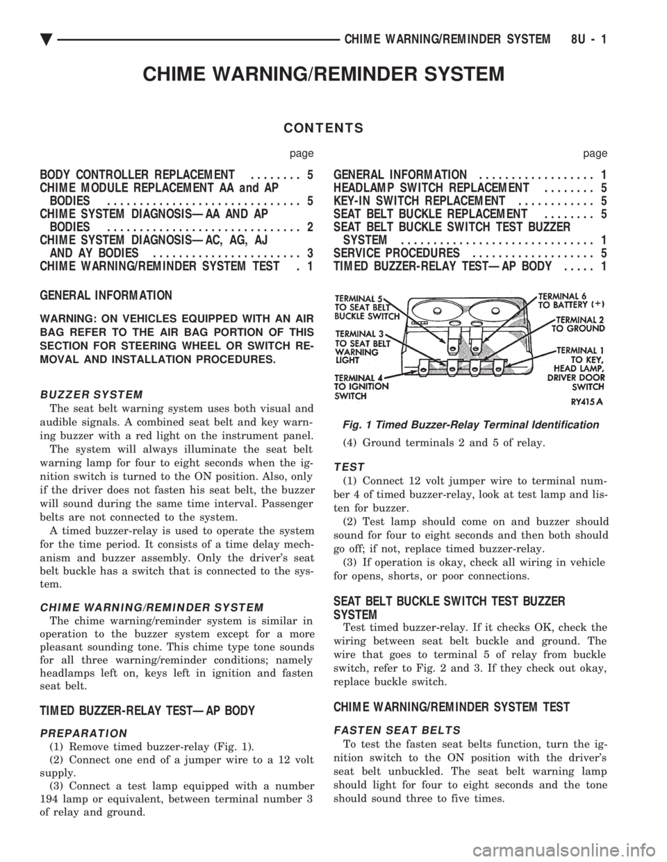
(1) Remove timed buzzer-relay (Fig. 1).
(2) Connect one end of a jumper wire to a 12 volt
supply. (3) Connect a test lamp equipped with a number
194 lamp or equivalent, between terminal number 3
of relay and ground. (4) Ground terminals 2 and 5 of relay.
TEST
(1) Connect 12 volt jumper wire to terminal num-
ber 4 of timed buzzer-relay, look at test lamp and lis-
ten for buzzer. (2) Test lamp should come on and buzzer should
sound for four to eight seconds and then both should
go off; if not, replace timed buzzer-relay. (3) If operation is okay, check all wiring in vehicle
for opens, shorts, or poor connections.
SEAT BELT BUCKLE SWITCH TEST BUZZER
SYSTEM
Test timed buzzer-relay. If it checks OK, check the
wiring between seat belt buckle and ground. The
wire that goes to terminal 5 of relay from buckle
switch, refer to Fig. 2 and 3. If they check out okay,
replace buckle switch.
CHIME WARNING/REMINDER SYSTEM TEST
FASTEN SEAT BELTS
To test the fasten seat belts function, turn the ig-
nition switch to the ON position with the driver's
seat belt unbuckled. The seat belt warning lamp
should light for four to eight seconds and the tone
should sound three to five times.
Fig. 1 Timed Buzzer-Relay Terminal Identification
Ä CHIME WARNING/REMINDER SYSTEM 8U - 1
Page 746 of 2438

HEADLAMPS LEFT ON
To test the headlamps left on function, turn head-
lamps on with drivers door open. Chime should
sound until headlamps are turned off or drivers door
is closed.
KEY LEFT IN IGNITION
To test the key left in ignition function, insert key
into the ignition and open drivers door. Chime
should sound until key is removed from ignition or
drivers door is closed.
CHIME SYSTEM DIAGNOSISÐAA AND AP BODIES
WARNING: ON VEHICLES EQUIPPED WITH AN AIR
BAG REFER TO THE AIR BAG PORTION OF THIS SECTION FOR STEERING WHEEL OR SWITCH RE-
MOVAL AND INSTALLATION PROCEDURES.
CONDITION: NO TONE WHEN IGNITION
SWITCH IS TURNED ON AND DRIVERS SEATBELT OR AUTOMATIC SHOULDER HARNESSIS UNBUCKLED
PROCEDURE
(1) Check seat belt buckle switch (drivers seat) or
rotary switch in automatic shoulder harness retrac-
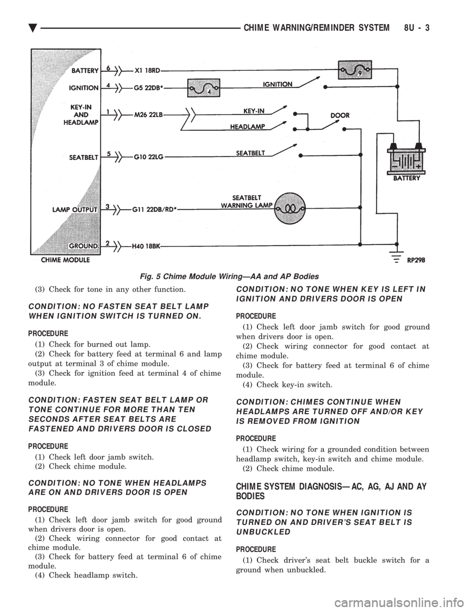
tor for a ground when unbuckled. (2) Check for battery feed at terminal 6 and igni-
tion feed at terminal 4 of chime module (Fig. 4 and
5).
Fig. 3 Seat Belt Warning System Diagnosis
Fig. 4 Chime Module Terminal IdentificationFig. 2 Buzzer System Wiring Schematic
8U - 2 CHIME WARNING/REMINDER SYSTEM Ä
Page 747 of 2438
(3) Check for tone in any other function.
CONDITION: NO FASTEN SEAT BELT LAMP WHEN IGNITION SWITCH IS TURNED ON.
PROCEDURE
(1) Check for burned out lamp.
(2) Check for battery feed at terminal 6 and lamp
output at terminal 3 of chime module. (3) Check for ignition feed at terminal 4 of chime
module.
CONDITION: FASTEN SEAT BELT LAMP OR TONE CONTINUE FOR MORE THAN TENSECONDS AFTER SEAT BELTS AREFASTENED AND DRIVERS DOOR IS CLOSED
PROCEDURE
(1) Check left door jamb switch.
(2) Check chime module.
CONDITION: NO TONE WHEN HEADLAMPS ARE ON AND DRIVERS DOOR IS OPEN
PROCEDURE
(1) Check left door jamb switch for good ground
when drivers door is open. (2) Check wiring connector for good contact at
chime module. (3) Check for battery feed at terminal 6 of chime
module. (4) Check headlamp switch.
CONDITION: NO TONE WHEN KEY IS LEFT IN
IGNITION AND DRIVERS DOOR IS OPEN
PROCEDURE
(1) Check left door jamb switch for good ground
when drivers door is open. (2) Check wiring connector for good contact at
chime module. (3) Check for battery feed at terminal 6 of chime
module. (4) Check key-in switch.
CONDITION: CHIMES CONTINUE WHENHEADLAMPS ARE TURNED OFF AND/OR KEYIS REMOVED FROM IGNITION
PROCEDURE
(1) Check wiring for a grounded condition between
headlamp switch, key-in switch and chime module. (2) Check chime module.
CHIME SYSTEM DIAGNOSISÐAC, AG, AJ AND AY
BODIES
CONDITION: NO TONE WHEN IGNITION IS
TURNED ON AND DRIVER'S SEAT BELT ISUNBUCKLED
PROCEDURE
(1) Check driver's seat belt buckle switch for a
ground when unbuckled.
Fig. 5 Chime Module WiringÐAA and AP Bodies
Ä CHIME WARNING/REMINDER SYSTEM 8U - 3
Page 748 of 2438
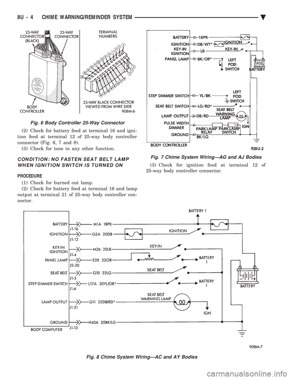
(2) Check for battery feed at terminal 16 and igni-
tion feed at terminal 12 of 25-way body controller
connector (Fig. 6, 7 and 8). (3) Check for tone in any other function.
CONDITION: NO FASTEN SEAT BELT LAMPWHEN IGNITION SWITCH IS TURNED ON
PROCEDURE
(1) Check for burned out lamp.
(2) Check for battery feed at terminal 16 and lamp
output at terminal 21 of 25-way body controller con-
nector. (3) Check for ignition feed at terminal 12 of
25-way body controller connector.
Fig. 6 Body Controller 25-Way Connector
Fig. 7 Chime System WiringÐAG and AJ Bodies
Fig. 8 Chime System WiringÐAC and AY Bodies
8U - 4 CHIME WARNING/REMINDER SYSTEM Ä