1993 CHEVROLET PLYMOUTH ACCLAIM low oil pressure
[x] Cancel search: low oil pressurePage 1065 of 2438
Wiring Diagram
Name Sheet Number
RS Amplifier ......................... .122, 123
Electronic Cluster ........................ .99, 100
Data Link Connector ....................... .100
Electronic Cluster Printed Circuit Board Connector .......201
Electronic Fuel Pump and Gauge System ..............36
Electronic Vehicle Information Center Connector ........189
Electronic Vehicle Information Center Engine Compartment Sensors ...................... .97, 98
Brake Fluid Level Sensor ......................98
Coolant Level Sensor .........................98
Data Link Connector .........................97
EVIC Engine Node ...........................98
Engine Air Conditioning and Heater System (3.0L, 3.3L & 3.8L Engine) ................55
A/C and Heater Blower Motor Resistor ..............55
A/C Blower Motor ...........................55
A/C Low Pressure Switch ......................55
A/C Switch ...............................55
A/C Variable Output Compressor Clutch .............55
Blower Switch .............................55
Defrost Switch .............................55
Illumination Lamps ..........................55
Engine Coolant Temperature Sending Unit ........30, 31, 32
Engine Coolant Temperature Sensor ..............19, 25
Engine Oil Level Sensor ..................... .31, 32
Engine Oil Pressure and Temperature Warning System (2.5L) .............................30
Engine Coolant Temperature Sending Unit ............30
Engine Oil Pressure Switch .....................30
Engine Oil Pressure and Temperature Warning System (3.0L) .............................31
Engine Coolant Temperature Sending Unit ............31
Engine Oil Level Sensor .......................31
Engine Oil Pressure Sending Unit/Switch ............31
Engine Oil Pressure and Temperature Warning System (3.3L & 3.8L) .............................32
Engine Coolant Temperature Sending Unit ............32
Engine Oil Level Sensor .......................32
Engine Oil Pressure Sending Unit/Switch ............32
Engine Starter System (2.5L) .....................12
Automatic Park/Neutral Start Switch ...............12
Back-Up Lamp Switch ........................12
Engine Starter Motor .........................12
Engine Starter Relay .........................12
Transmission Solenoid ........................12
Engine Starter System (3.0L, 3.3L & 3.8L) .............13
Engine Starter Motor .........................13
Engine Starter Relay .........................13
Electronic Fuel Pump and Gauge System ..............36
Fuel Pump Motor ...........................36
Fuel Pump Relay ...........................36
Fuel Tank Level Gauge Sending Unit Fuel Switch .......36
EVAP/Purge Solenoid .................... .15, 20, 27
Fan Control Relay ......................... .52, 54
Front End Lighting-Aero Headlamps (Dodge Dynasty) . . .69, 70 Left Headlamp (Aero) .........................70
Left Park/Turn Signal Lamp .....................70
Left Side Marker Lamp ........................70Wiring Diagram
Name Sheet Number
Right Headlamp (Aero) ........................69
Right Park/Turn Signal Lamp ....................69
Right Side Marker Lamp .......................69
Front End Lighting-Aero Headlamps with Daytime Running Lights (Dodge Dynasty) .................... .71, 72
Daytime Running Lamp Module ..................72
Left Headlamp (Aero) .........................72
Left Park/Turn Signal Lamp .....................72
Left Side Marker Lamp ........................72
Right Headlamp (Aero) ........................71
Right Park/Turn Signal Lamp ....................71
Right Side Marker Lamp .......................71
Front End Lighting Concealed Headlamps (Imperial) . . . .73, 74
Left Cornering Lamp .........................74
Left High Beam Headlamp ......................74
Left Low Beam Headlamp ......................74
Left Park Lamps ............................74
Left Park/Turn Signal Lamp .....................74
Left Side Turn Lamp .........................74
Right Cornering Lamp ........................73
Right High Beam Headlamp .....................73
Right Low Beam Headlamp .....................73
Right Park Lamps ...........................73
Right Park/Turn Signal Lamp ....................73
Right Side Turn Lamp ........................73
Front End Lighting Concealed Headlamps with D.R.L.1 (Imperial) .......................... .75, 76, 77
Daytime Running Lamp Module ..................76
Left Cornering Lamp .........................77
Left High Beam Headlamp ......................77
Left Low Beam Headlamp ......................77
Left Park Lamps ............................77
Left Park/Turn Signal Lamp .....................77
Left Side Turn Lamp .........................77
Right Cornering Lamp ........................75
Right High Beam Headlamp .....................75
Right Low Beam Headlamp .....................75
Right Park Lamps ...........................75
Right Park/Turn Signal Lamp ....................75
Right Side Turn Lamp ........................75
Front End Lighting Concealed Headlamps with D.R.L.2 (Imperial) .......................... .78, 79, 80
Daytime Running Lamp Module ..................79
Left Cornering Lamp .........................80
Left High Beam Headlamp ......................80
Left Low Beam Headlamp ......................80
Left Park Lamps ............................80
Left Park/Turn Signal Lamp .....................80
Left Side Turn Lamp .........................80
Right Cornering Lamp ........................78
Right High Beam Headlamp .....................78
Right Low Beam Headlamp .....................78
Right Park Lamps ...........................78
Right Park/Turn Signal Lamp ....................78
Right Side Turn Lamp ........................78
Front End Lighting Concealed Headlamps (New Yorker/5th Avenue) .............................. .81, 82
Ä WIRING DIAGRAMS AC-AY BODY 8W - 315
Page 1067 of 2438
Wiring Diagram
Name Sheet Number
Blower Slide Control .........................51
Illumination Lamp ...........................51
Resistor .................................51
Horn System ............................ .63, 64
Clockspring ...............................63
Horn (Hi-note) .............................63
Horn (Lo-note) .............................63
Horn Relay ...............................63
Horn Switch ..............................63
Idle Air Control Motor .................... .14, 21, 26
Ignition Switch .............................4,11
Injectors ............................ .15, 20, 24
Illuminated Entry System ........................91
Left Front Door Courtesy Lamp ..................91
Left Front Door Illuminated Entry Switch ............91
Right Front Door Courtesy Lamp .................91
Right Front Door Illuminated Entry Switch ...........91
Instrument Panel to Multi-Function Switch Wiring .......180
Instrument Panel Ground System ...................86
Interface Grommet ............................58
Intermittent Wiper System .................... .61, 62
Intermittent Wiper Motor ......................62
Intermittent Wiper Switch ......................61
Washer Pump Motor .........................61
Windshield Washer Low Fluid Level Sensor ...........61
Key Cylinders .......................... .131, 135
Key-In Switch .......................... .104, 107
Keyless Entry Connectors ...................... .208
Lamp Outage Module ...................... .96, 209
Lamps Ash Receiver Lamp ........................ .111
Back-Up Lamps ................ .161, 162, 163, 164
Center High Mounted Stop Lamp ......161, 162, 163, 164
Cornering Lamp Left ...............74, 77, 80, 82, 84
Cornering Lamp Right ..............73, 75, 78, 81, 83
Courtesy Lamps ................... .87, 88, 89, 90
Deck Lid Ajar Warning Lamp ....................95
Door Ajar Lamps ...........................95
Door Courtesy Lamp ................ .87, 88, 90, 91
Glove Box Lamp .......................... .111
Halo Lamp .......................... .104, 106
Headlamp-Left ............... .70, 72, 74, 80, 82, 84
Headlamp-Right ............ .69, 71, 73, 75, 78, 81, 83
Headlamp Switch Lamp .......................85
Illuminated Entry Lamps .......................91
Illumination Lamp ..................... .51, 53, 55
License Lamp .................. .161, 162, 163, 164
Low Engine Oil Pressure Lamp .............30, 31, 32
Low Windshield Washer Fluid Warning Lamp .........95
Parking/Turn Lamp-Left ........70, 72, 74, 77, 80, 82, 84
Parking/Turn Lamp-Right .......69, 71, 73, 75, 78, 81, 83
Park Lamp-Left ............................74
Park Lamp-Right ...........................73
Reading Lamps ............................90
Security Lamp ..................... .128, 132, 136
Side Marker Lamp-Left Front ............70, 72, 82, 84
Side Marker Lamp-Right Front ...........69, 71, 81, 83Wiring Diagram
Name Sheet Number
Side Marker Lamp-Left Rear ................161, 163
Side Marker Lamp-Right Rear ...............162, 164
Tail, Stop/Turn Signal Lamp-Left Rear ..........161, 163
Tail, Stop/Turn Signal Lamp-Right Rear .........162, 164
Transmission Range Lamp .....................85
Trunk Lamp ...............................90
Turn Signal Lamp-Left Front ...............74, 77, 80
Turn Signal Lamp-Right Front ..............73, 75, 78
Underhood Lamp ......................... .159
Vanity Mirror ..............................89
Visor Lamp ...............................89
Left Body to Instrument Panel Wiring ............190, 191
Left Front Door Jamb Switch .....................87
Left Rear Door Jamb Switch ......................87
MAP Sensor .......................... .18, 21, 26
Mechanical Cluster Printed Circuit Board .............167
Mechanical Cluster Printed Circuit Board Connectors ......166
Memory Power Seat & Mirror Connector .............204
Memory Power Seat System ...........151, 152, 153, 154
Circuit Breaker ........................... .153
Left Power Seat Motors ..................... .153
Left Power Seat Switch ...................... .152
Left Power Seat Switch Insulator ................152
Left Recliner Motor ........................ .154
Memory Module ................ .151, 152, 153, 154
Recliner Position Sense Resistor .................154
Recliner Seat Switch ....................... .152
Relay Bank ............................. .153
Seat Memory Selector Switch ...................151
Seat Track Position Sense Resistor ...............154
Memory Power Seat System Connectors .............205
Message Center Connector ..................... .207
Mirror-Heated ....................... .143, 144, 146
Mirror-Power .................... .143, 144, 145, 146
Modules Airbag System Diagnostic Module .................57
Air Suspension Control Module ................41, 43
ATC Power Module ........................ .115
Daytime Running Lamp Module ...........72, 76, 79, 84
Lamp Outage Module .................... .96, 209
Mirror Memory Module .................. .143, 144
Power Seat Memory Module .........151, 152, 153, 154
Powertrain Control Module ........14, 15, 16, 17, 18, 19,
20, 21, 22, 23, 24, 25, 26, 27, 28, 29, 37
Relay Module ............................ .171
Remote Keyless Entry Module ...............141, 142
Security Alarm Module ......127, 128, 129, 130, 131, 132,
133, 134, 135, 136, 137, 138
Sunroof Control .......................... .147
Transmission Control Module ...............33, 34, 35
Motors ABS Pump Motor ...........................46
Antenna Motor ........................... .118
Blower-A/C ............................ .53, 55
Blower ATC ............................. .115
Blower-Heater .............................51
Compressor Motor ....................... .40, 42
Ä WIRING DIAGRAMS AC-AY BODY 8W - 317
Page 1071 of 2438
Wiring Diagram
Name Sheet Number
Splice Z1-3 ............... .47, 68, 74, 77, 80, 82, 84
Splice Z1-4 .......... .38, 47, 70, 72, 74, 77, 80, 82, 84
Splice Z1-5 ............................. .155
Splice Z1-6 .....36, 124, 125, 127, 131, 135, 160, 162, 164
Splice Z1-7 .................... .39, 160, 162, 164
Splice Z1-8 ........................... .86, 115
Splice Z1-9 .................. .61, 86, 118, 140, 141
Splice Z1-10 ..............................46
Splice Z1-11 .................. .161, 162, 163, 164
Splice Z1-12 .....52, 54, 56, 63, 69, 71, 73, 75, 78, 81, 83
Splice Z1-13 ............. .90, 124, 125, 147, 162, 164
Splice Z1-14 . . . .91, 127, 131, 135, 143, 149, 152, 158, 165
Splice Z1-15 ........... .67, 88, 91, 112, 127, 131, 135,
149, 152, 155, 158, 165
Splice Z1-16 .....88, 91, 112, 127, 131, 135, 150, 155, 165
Splice Z1-17 ....................... .54, 56, 113
Splice Z1-18 ......................... .162, 164
Splice Z1-19 .............. .70, 72, 73, 74, 75, 77, 78,
80, 81, 82, 83, 84
Splice Z2 .......................... .86, 98, 99
Splice Z2-1 ...............................98
Splice Z2-2 ......................... .36, 39, 43
Splice Z12 ....................... .16, 22, 24, 35
Splice Z13 ............................7,9,35
Splice Z14 ...............................35
Stop Lamps .................... .161, 162, 163, 164
Stop Lamp Switch ......................... .38, 59
Switches A/C Ambient Temp ...................... .56, 114
A/C Cycling Switch ..........................54
A/C Fan Cutout ........................ .56, 114
A/C Defrost ........................... .53, 55
A/C Heater Blower ....................... .53, 55
A/C High Pressure Cutout ................54, 56, 114
A/C Low Pressure .................... .53, 55, 114
ATC Temp Control ......................... .116
Automatic Transmission Park/Neutral Position .........12
Backup Lamp ..............................12
Brake Warning Lamp .........................11
Deck Lid Release ......................... .111
Defrost .............................. .53, 55
Dimmer-Headlamp ..........................66
Door Ajar .......................... .92, 93, 94
Door Jamb ............................ .87, 88
Door Window-Left Front ..................... .157
Door Window-Left Rear ..................... .157
Door Window-Right Front .................... .158
Door Window-Right Rear .................... .158
Engine Oil Pressure .................... .30, 31, 32
Fuel Tank Level Gauge Sending Unit Switch ..........36
Glove Box Lamp .......................... .111
Hazard Flasher .............................60
Headlamp ..............................1,65
Headlamp Dimmer .........................1,66
Heated Rear Window ......................4,148
Heater Bi-Level Control Switch ...................51
Horn ...................................63Wiring Diagram
Name Sheet Number
Ignition ................................4,11
Illuminated Entry ...........................91
Illuminated Visor Vanity Mirror Switch ..............89
Intermittent Wiper ...........................61
Key-in .......................... .104, 107, 109
Left Rear Door Jamb Switch ....................87
Optical Horn .............................1,66
Park Brake ...............................11
Power Door Lock-Left Front ................... .139
Power Door Lock-Right Front ...................140
Power Mirrors ........................ .143, 145
Power Recliner Seat .................... .152, 155
Power Seat ................... .149, 150, 152, 155
Power Steering Switch .................... .19, 25
Seat Belt .................................67
Security Alarm-Hood ................. .128, 132, 136
Seat Memory Selector Switch ...................151
Sliding Roof Position ....................... .147
Stop Lamp w/Speed Control ..................38, 59
Stop Lamp w/o Speed Control ................38, 59
Sunroof ............................... .147
Transmission Range Switch .....................35
Turn Signal ...............................60
Vanity Lamp ..............................89
Vehicle Speed Control ........................37
Throttle Body Fuel Injection (TBI) Ignition System (2.5L) ....................... .14, 15, 16, 17, 18
Automatic Shut Down Relay ....................15
Data Link Connector .........................14
Distributor ...............................17
Engine Coolant Temperature Sensor ..........17, 19, 30
EVAP/Purge Solenoid .........................15
Exhaust Gas Recirculation Solenoid ................14
Heated Oxygen Sensor ........................14
Idle Air Control Motor ........................14
Ignition Coil ...............................15
Injector .................................15
MAP Sensor ..............................18
Powertrain Control Module ...........14, 15, 16, 17, 18
Throttle Position (Sensor) ......................18
Vehicle Speed Sensor ........................17
Throttle Position (Sensors) ..................18, 21, 26
Transmission Controller Connector .................177
Transmission Control Module ................33, 34, 35
Transmission Control System ................33, 34, 35
Back-Up Lamp Relay .........................33
Park/Neutral Position Switch ....................33
Safety Shut Down Relay .......................35
Transmission Control Module ...............33, 34, 35
Transmission Output Speed Sensor ................34
Transmission Range Switch .....................35
Transmission Solenoids and Pressure Switches ........35
Turbine Speed Sensor ........................34
Transmission Output Speed Sensor .................34
Transmission Range Lamp with Electronic Cluster ........85
Transmission Solenoid Connector ..................179
Transmission Solenoids and Pressure Switches ..........35
Ä WIRING DIAGRAMS AC-AY BODY 8W - 321
Page 1289 of 2438
Wiring Diagram
Name Sheet Number
Splice F35-2 ......................... .113, 115
Splice F35-3 ............................ .114
Splice G5-1 ................ .70, 73, 77, 84, 88, 127
Splice G5-2 ........................... .81, 88
Splice G7 .......................... .21, 24, 35
Splice G9 .......................... .70, 73, 78
Splice G74 ........................ .83, 102, 104
Splice G75 ........................ .83, 102, 104
Splice K4 ............................. .21, 30
Splice K4-1 ......................... .17, 21, 29
Splice K4-2 ...............................32
Splice K4-3 ...............................27
Splice K6 ............................. .29, 30
Splice K7 .......................... .22, 26, 30
Splice K22 ............................ .26, 37
Splice K24 ...............................26
Splice L1 ........................ .129, 133, 137
Splice L7 ............................ .54, 136
Splice L7-1 ........................... .45, 49
Splice L7-2 ........................ .46, 50, 132
Splice L7-3 ............................. .130
Splice L7-4 ............................. .129
Splice L7-5 ............................. .131
Splice L7-6 .......................... .132, 136
Splice L7-7 .......................... .132, 136
Splice L33 ....................... .45, 46, 49, 50
Splice L43 ....................... .45, 46, 49, 50
Splice L50 .......................... .140, 141
Splice L61 ............... .45, 46, 49, 50, 58, 76, 78
Splice L62 .......................... .130, 131
Splice L63 .............................. .130
Splice L94 ......................... .53, 79, 81
Splice M1-1 ............ .16, 73, 77, 87, 121, 123, 125
Splice M1-2 ............... .16, 61, 77, 87, 101, 103,
117, 119, 121, 123, 125
Splice M1-4 ................... .118, 120, 124, 126
Splice M1-5 ............................. .122
Splice M1-6 ............................. .122
Splice M2 ................. .117, 119, 121, 123, 125
Splice M2-1 ......................... .118, 126
Splice P34 .............................. .116
Splice P76-1 ........................... .97, 99
Splice T13 ...............................39
Splice T16 ...............................36
Splice T24 ......................... .13, 14, 15
Splice T41 ............................ .15, 38
Splice V23 .............................. .105
Splice X13 ...............................62
Splice X15 ...............................61
Splice X60 ...............................63
Splice Z0 .......................9,11,21,25,37
Splice Z1 .................9,33,44,46,48,50,100
Splice Z1-2 ...............................68
Splice Z1-3 ........................... .59, 67
Splice Z1-4 ................. .43, 45, 47, 49, 65, 89
Splice Z1-5 .......... .14, 43, 45, 47, 49, 59, 65, 67, 89
Splice Z1-7 ...............................51Wiring Diagram
Name Sheet Number
Splice Z1-8 .......... .43, 45, 47, 49, 52, 56, 60, 90, 93
Splice Z1-9 ........... .97, 99, 109, 111, 113, 114, 115
Splice Z1-10 ...................... .100, 109, 115
Splice Z1-11 ....................... .98, 100, 109
Splice Z1-12 ................... .94, 105, 129, 140
Splice Z1-14 ............................ .129
Splice Z1-15 ......................... .129, 140
Splice Z1-16 ............................ .130
Splice Z1-17 .................. .135, 139, 141, 142
Splice Z1-18 ............................ .141
Splice Z1-19 ......................... .134, 138
Splice Z1-20 ......................... .132, 136
Splice Z1-21 ..............................98
Splice Z1-28 ................. .44, 46, 48, 50, 65, 69
Splice Z2 ................................72
Splice Z2-1 ................... .72, 77, 86, 98, 127
Splice Z3 ................. .52, 55, 66, 73, 101, 103
Splice Z3-1 ................ .52, 55, 66, 73, 121, 123
Splice Z12 ...........................9,21,33
Splice Z13 ...............................37
Splice Z14 ...............................37
Speaker Choke ..............................60
Stereo Radio ....................... .61, 62, 63, 64
Stop Lamp Switch ............................59
Switches ABS Warning Switch .........................70
A/C Blower Switch ..........................90
A/C Cycling Switch ..........................92
A/C High Pressure Switch ......................92
A/C Low Pressure Switch ......................91
Brake Switch ..............................70
Clutch Pedal Position Switch ....................14
Deck Lid Ajar Switch .................... .122, 124
Deck Lid Warning Switch ................83, 102, 104
Dimmer Switch (Slide Control) ...................51
Door Ajar Switch-Left Front .................102, 104
Door Ajar Switch-Right Front ................102, 104
Door Lock Switch ...................... .115, 116
Engine Oil Pressure Switch/Sending Unit ..........40, 41
Fog Lamp Switch ........................ .51, 55
Fuse Panel Switch ...........................51
Glove Box Lamp Switch ............101, 103, 123, 125
Headlamp ............................ .51, 55
Heated Rear Window Switch ................8,94,95
Heater Blower Switch .........................93
Horn Switch ..............................65
Ignition Switch .........................2,7,42
Intermittent Wiper Switch ......................66
Key Disarm Switch ..................... .115, 116
Left Door Illuminated Entry Switch ...............109
Left Door Master Window Lift Switch ..............111
Left Window Lift Switch ..................... .110
Lift Gate Ajar Switch ................. .102, 104, 125
Lower Power (Top) Switch .....................96
Lumbar Switch ........................... .114
Manual Transmission Back-Up Lamp Switch ..........14
Mercury Switch ............................16
Ä WIRING DIAGRAMS AG-AJ BODY 8W - 539
Page 1467 of 2438
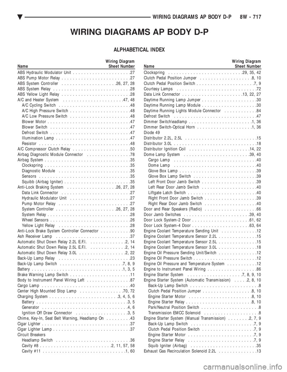
WIRING DIAGRAMS AP BODY D-P
ALPHABETICAL INDEX
Wiring Diagram
Name Sheet Number
ABS Hydraulic Modulator Unit .....................27
ABS Pump Motor Relay .........................27
ABS System Controller ................... .26, 27, 28
ABS System Relay ............................28
ABS Yellow Light Relay .........................28
A/C and Heater System ..................... .47, 48
A/C Cycling Switch ..........................48
A/C High Pressure Switch ......................48
A/C Low Pressure Switch ......................48
Blower Motor ..............................47
Blower Switch .............................47
Defrost Switch .............................47
Illumination Lamp ...........................47
Resistor .................................48
A/C Compressor Clutch Relay .....................50
Airbag Diagnostic Module Connector ................78
Airbag System ...............................35
Clockspring ...............................35
Diagnostic Module ..........................35
Sensors .................................35
Squibb (Airbag Igniter) ........................35
Anti-Lock Braking System ..................26, 27, 28
Data Link Connector .........................27
Hydraulic Modulator Unit ......................27
Pump Motor Relay ..........................27
System Controller ..................... .26, 27, 28
System Relay ..............................28
Wheel Sensors .............................26
Yellow Light Relay ..........................28
Anti-Lock Brake System Controller Connector ...........90
Ash Receiver Lamp ...........................37
Automatic Shut Down Relay 2.2L E.F.I. .............2,14
Automatic Shut Down Relay 2.5L E.F.I. .............2,14
Automatic Shut Down Relay 3.0L .................2,22
Back-Up Lamp Relay ..........................23
Back-Up Lamp Switch .......................7,8,9
Battery .................................1,3,5
Brake Warning Lamp Switch ......................11
Body to Instrument Panel Wiring Left ................87
Cargo Lamp ................................40
Center High Mounted Stop Lamp ................70, 72
Charging System .........................3,4,5,6
Battery .................................3,5
Generator ...............................4,6
Ignition Off Draw Connector ...................3,5
Chime, Key-In, Seat Belt Warning, Headlamp On .........43
Cigar Lighter ................................37
Cigar Lighter Lamp ............................37
Circuit Breakers Headlamp Switch ...........................36
Cavity #8 ..........................2,11,57,58
Cavity #11 ..............................1,60Wiring Diagram
Name Sheet Number
Clockspring .......................... .29, 35, 42
Clutch Pedal Position Jumper ...................8,10
Clutch Pedal Position Switch .....................7,9
Courtesy Lamps .............................72
Data Link Connector ..................... .13, 22, 27
Daytime Running Lamp Jumper ....................30
Daytime Running Lamp Module ....................30
Daytime Running Lights Module Connector ............84
Defrost Switch ..............................47
Dimmer Switch\eadlamp .......................1,36
Dimmer Switch-Optical Horn ....................1,36
Diode 49
Distributor 2.2L, 2.5L ..........................15
Distributor 3.0L ..............................18
Distributor Ignition Coil ..................... .14, 22
Dome Lamp System ....................... .39, 40
Cargo Lamp ..............................40
Dome Lamp ..............................40
Glove Box Lamp ............................39
Glove Box Lamp Switch .......................39
Left Front Door Jamb Switch ....................39
Left Rear Door Jamb Switch ....................40
Liftgate Latch Switch .........................40
Right Front Door Jamb Switch ...................39
Right Rear Door Jamb Switch ...................40
Door and Rear Speakers (Radio) ...................66
Door Jamb Switches ....................... .39, 40
Door Lock System-2 Door .................... .61, 62
Door Lock System-4 Door .................... .63, 64
Engine Coolant Temperature Sending Unit .............12
Engine Coolant Temperature Sensor 2.2L ..............15
Engine Coolant Temperature Sensor 2.5L ..............15
Engine Coolant Temperature Sensor 3.0L ..............18
Engine Oil Pressure Sending Unit/Switch ..............12
Engine Oil Pressure Switch .......................12
Engine Oil Pressure and Temperature System ...........12
Engine to Instrument Panel Wiring ..................86
Engine Starter System ....................7,8,9,10
Engine Starter System (Automatic Transmission) .....2,8,10
Back-Up Lamp Switch .........................8
Clutch Pedal Position Jumper ..................8,10
Engine Starter Motor .......................8,10
Engine Starter Relay ........................8,10
Park/Neutral Position Switch .....................8
Transmission EMCC Solenoid ....................8
Engine Starter System (Manual Transmission) ........2,7,9
Back-Up Lamp Switch .......................7,9
Clutch Pedal Position Switch ...................7,9
Engine Starter Motor ........................7,9
Engine Starter Relay ........................7,9
Squib Igniter (Airbag) ........................35
Exhaust Gas Recirculation Solenoid 2.2L ..............13
Ä WIRING DIAGRAMS AP BODY D-P 8W - 717
Page 1468 of 2438
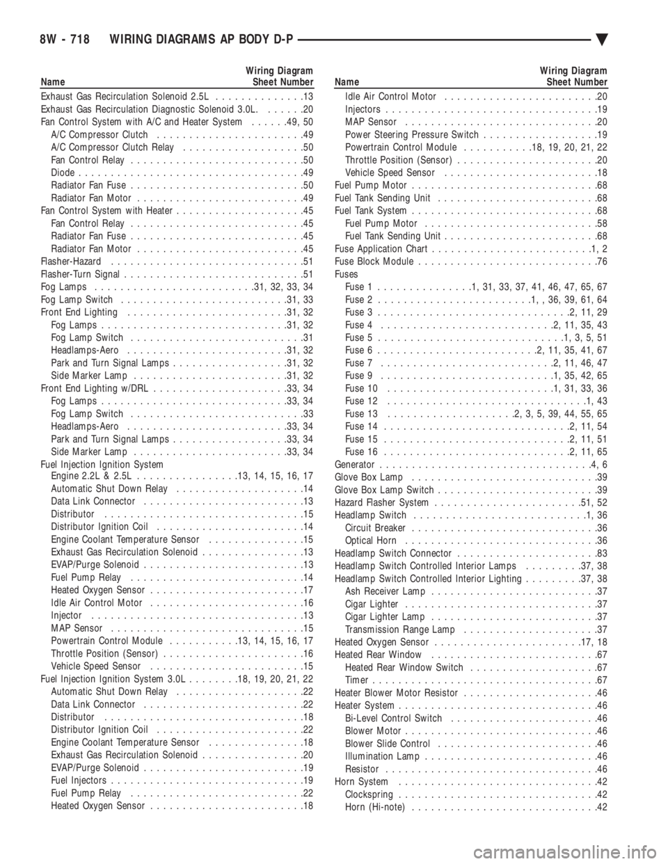
Wiring Diagram
Name Sheet Number
Exhaust Gas Recirculation Solenoid 2.5L ..............13
Exhaust Gas Recirculation Diagnostic Solenoid 3.0L. ......20
Fan Control System with A/C and Heater System ......49, 50
A/C Compressor Clutch .......................49
A/C Compressor Clutch Relay ...................50
Fan Control Relay ...........................50
Diode ...................................49
Radiator Fan Fuse ...........................50
Radiator Fan Motor ..........................49
Fan Control System with Heater ....................45
Fan Control Relay ...........................45
Radiator Fan Fuse ...........................45
Radiator Fan Motor ..........................45
Flasher-Hazard ..............................51
Flasher-Turn Signal ............................51
Fog Lamps ........................ .31, 32, 33, 34
Fog Lamp Switch ......................... .31, 33
Front End Lighting ........................ .31, 32
Fog Lamps ............................ .31, 32
Fog Lamp Switch ...........................31
Headlamps-Aero ........................ .31, 32
Park and Turn Signal Lamps ..................31, 32
Side Marker Lamp ....................... .31, 32
Front End Lighting w/DRL .................... .33, 34
Fog Lamps ............................ .33, 34
Fog Lamp Switch ...........................33
Headlamps-Aero ........................ .33, 34
Park and Turn Signal Lamps ..................33, 34
Side Marker Lamp ....................... .33, 34
Fuel Injection Ignition System Engine 2.2L & 2.5L ............... .13, 14, 15, 16, 17
Automatic Shut Down Relay ....................14
Data Link Connector .........................13
Distributor ...............................15
Distributor Ignition Coil .......................14
Engine Coolant Temperature Sensor ...............15
Exhaust Gas Recirculation Solenoid ................13
EVAP/Purge Solenoid .........................13
Fuel Pump Relay ...........................14
Heated Oxygen Sensor ........................17
Idle Air Control Motor ........................16
Injector .................................13
MAP Sensor ..............................15
Powertrain Control Module ...........13, 14, 15, 16, 17
Throttle Position (Sensor) ......................16
Vehicle Speed Sensor ........................15
Fuel Injection Ignition System 3.0L ........18, 19, 20, 21, 22
Automatic Shut Down Relay ....................22
Data Link Connector .........................22
Distributor ...............................18
Distributor Ignition Coil .......................22
Engine Coolant Temperature Sensor ...............18
Exhaust Gas Recirculation Solenoid ................20
EVAP/Purge Solenoid .........................19
Fuel Injectors ..............................19
Fuel Pump Relay ...........................22
Heated Oxygen Sensor ........................18Wiring Diagram
Name Sheet Number
Idle Air Control Motor ........................20
Injectors .................................19
MAP Sensor ..............................20
Power Steering Pressure Switch ..................19
Powertrain Control Module ...........18, 19, 20, 21, 22
Throttle Position (Sensor) ......................20
Vehicle Speed Sensor ........................18
Fuel Pump Motor .............................68
Fuel Tank Sending Unit .........................68
Fuel Tank System .............................68
Fuel Pump Motor ...........................58
Fuel Tank Sending Unit ........................68
Fuse Application Char t.........................1,2
Fuse Block Module ............................76
Fuses Fuse 1 ...............1,31,33,37,41,46,47,65,67
Fuse 2 ........................1,,36,39,61,64
Fuse 3 ..............................2,11,29
Fuse 4 ...........................2,11,35,43
Fuse 5 .............................1,3,5,51
Fuse 6 .........................2,11,35,41,67
Fuse 7 ...........................2,11,46,47
Fuse 9 ...........................1,35,42,65
Fuse 10 ..........................1,31,33,36
Fuse 12 ...............................1,43
Fuse 13 ....................2,3,5,39,44,55,65
Fuse 14 .............................2,11,54
Fuse 15 .............................2,11,51
Fuse 16 .............................2,11,65
Generator .................................4,6
Glove Box Lamp .............................39
Glove Box Lamp Switch .........................39
Hazard Flasher System ...................... .51, 52
Headlamp Switch ...........................1,36
Circuit Breaker .............................36
Optical Horn ..............................36
Headlamp Switch Connector ......................83
Headlamp Switch Controlled Interior Lamps .........37, 38
Headlamp Switch Controlled Interior Lighting .........37, 38
Ash Receiver Lamp ..........................37
Cigar Lighter ..............................37
Cigar Lighter Lamp ..........................37
Transmission Range Lamp .....................37
Heated Oxygen Sensor ...................... .17, 18
Heated Rear Window ..........................67
Heated Rear Window Switch ....................67
Timer ...................................67
Heater Blower Motor Resistor .....................46
Heater System ...............................46
Bi-Level Control Switch .......................46
Blower Motor ..............................46
Blower Slide Control .........................46
Illumination Lamp ...........................46
Resistor .................................46
Horn System ...............................42
Clockspring ...............................42
Horn (Hi-note) .............................42
8W - 718 WIRING DIAGRAMS AP BODY D-P Ä
Page 1471 of 2438
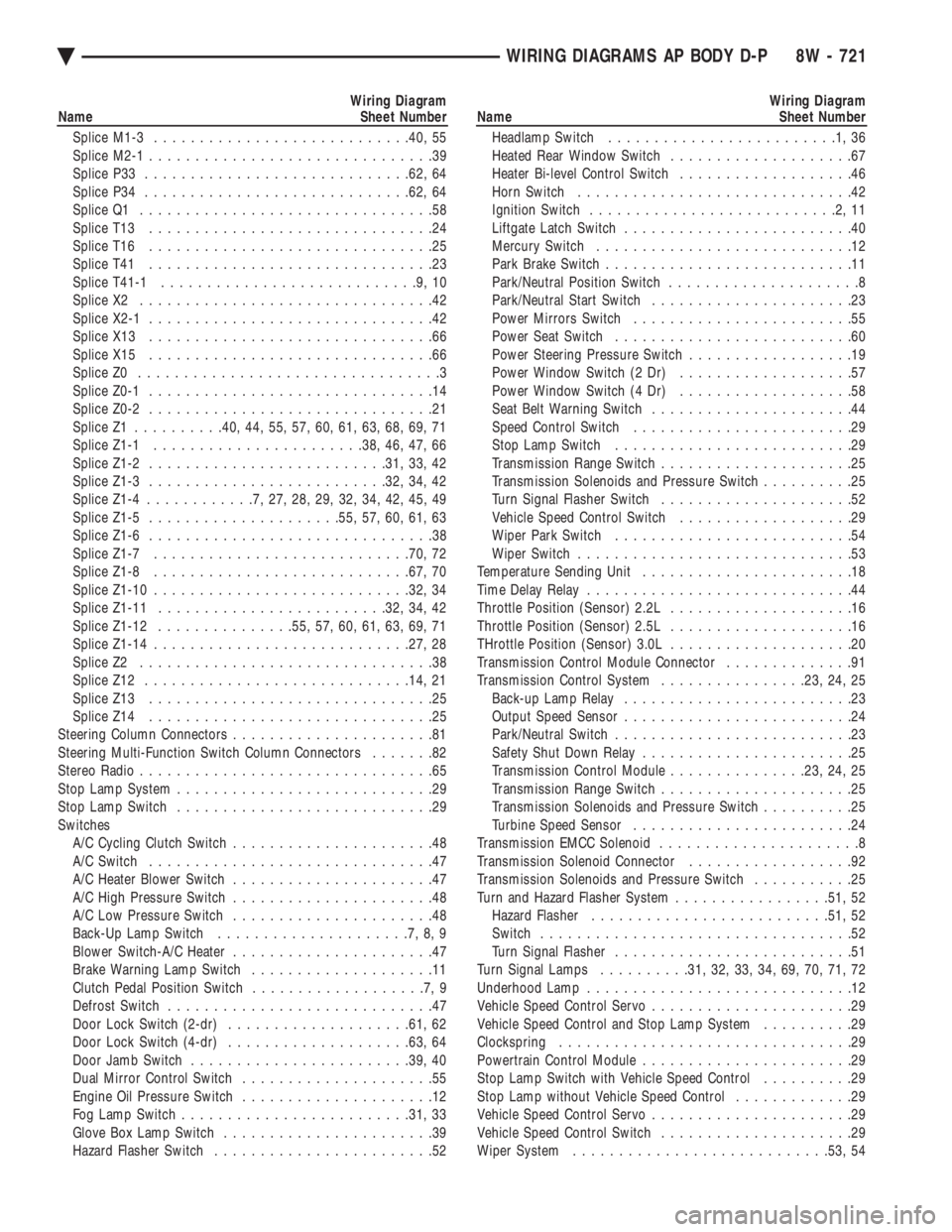
Wiring Diagram
Name Sheet Number
Splice M1-3 ........................... .40, 55
Splice M2-1 ...............................39
Splice P33 ............................ .62, 64
Splice P34 ............................ .62, 64
Splice Q1 ................................58
Splice T13 ...............................24
Splice T16 ...............................25
Splice T41 ...............................23
Splice T41-1 ............................9,10
Splice X2 ................................42
Splice X2-1 ...............................42
Splice X13 ...............................66
Splice X15 ...............................66
Splice Z0 .................................3
Splice Z0-1 ...............................14
Splice Z0-2 ...............................21
Splice Z1 ......... .40, 44, 55, 57, 60, 61, 63, 68, 69, 71
Splice Z1-1 ...................... .38, 46, 47, 66
Splice Z1-2 ......................... .31, 33, 42
Splice Z1-3 ......................... .32, 34, 42
Splice Z1-4 ............7,27,28,29,32,34,42,45,49
Splice Z1-5 .................... .55, 57, 60, 61, 63
Splice Z1-6 ...............................38
Splice Z1-7 ........................... .70, 72
Splice Z1-8 ........................... .67, 70
Splice Z1-10 ........................... .32, 34
Splice Z1-11 ........................ .32, 34, 42
Splice Z1-12 .............. .55, 57, 60, 61, 63, 69, 71
Splice Z1-14 ........................... .27, 28
Splice Z2 ................................38
Splice Z12 ............................ .14, 21
Splice Z13 ...............................25
Splice Z14 ...............................25
Steering Column Connectors ......................81
Steering Multi-Function Switch Column Connectors .......82
Stereo Radio ................................65
Stop Lamp System ............................29
Stop Lamp Switch ............................29
Switches A/C Cycling Clutch Switch ......................48
A/C Switch ...............................47
A/C Heater Blower Switch ......................47
A/C High Pressure Switch ......................48
A/C Low Pressure Switch ......................48
Back-Up Lamp Switch .....................7,8,9
Blower Switch-A/C Heater ......................47
Brake Warning Lamp Switch ....................11
Clutch Pedal Position Switch ...................7,9
Defrost Switch .............................47
Door Lock Switch (2-dr) ................... .61, 62
Door Lock Switch (4-dr) ................... .63, 64
Door Jamb Switch ....................... .39, 40
Dual Mirror Control Switch .....................55
Engine Oil Pressure Switch .....................12
Fog Lamp Switch ........................ .31, 33
Glove Box Lamp Switch .......................39
Hazard Flasher Switch ........................52Wiring Diagram
Name Sheet Number
Headlamp Switch .........................1,36
Heated Rear Window Switch ....................67
Heater Bi-level Control Switch ...................46
Horn Switch ..............................42
Ignition Switch ...........................2,11
Liftgate Latch Switch .........................40
Mercury Switch ............................12
Park Brake Switch ...........................11
Park/Neutral Position Switch .....................8
Park/Neutral Start Switch ......................23
Power Mirrors Switch ........................55
Power Seat Switch ..........................60
Power Steering Pressure Switch ..................19
Power Window Switch (2 Dr) ...................57
Power Window Switch (4 Dr) ...................58
Seat Belt Warning Switch ......................44
Speed Control Switch ........................29
Stop Lamp Switch ..........................29
Transmission Range Switch .....................25
Transmission Solenoids and Pressure Switch ..........25
Turn Signal Flasher Switch .....................52
Vehicle Speed Control Switch ...................29
Wiper Park Switch ..........................54
Wiper Switch ..............................53
Temperature Sending Unit .......................18
Time Delay Relay .............................44
Throttle Position (Sensor) 2.2L ....................16
Throttle Position (Sensor) 2.5L ....................16
THrottle Position (Sensor) 3.0L ....................20
Transmission Control Module Connector ..............91
Transmission Control System ................23, 24, 25
Back-up Lamp Relay .........................23
Output Speed Sensor .........................24
Park/Neutral Switch ..........................23
Safety Shut Down Relay .......................25
Transmission Control Module ...............23, 24, 25
Transmission Range Switch .....................25
Transmission Solenoids and Pressure Switch ..........25
Turbine Speed Sensor ........................24
Transmission EMCC Solenoid ......................8
Transmission Solenoid Connector ..................92
Transmission Solenoids and Pressure Switch ...........25
Turn and Hazard Flasher System .................51, 52
Hazard Flasher ......................... .51, 52
Switch ..................................52
Turn Signal Flasher ..........................51
Turn Signal Lamps ..........31, 32, 33, 34, 69, 70, 71, 72
Underhood Lamp .............................12
Vehicle Speed Control Servo ......................29
Vehicle Speed Control and Stop Lamp System ..........29
Clockspring ................................29
Powertrain Control Module .......................29
Stop Lamp Switch with Vehicle Speed Control ..........29
Stop Lamp without Vehicle Speed Control .............29
Vehicle Speed Control Servo ......................29
Vehicle Speed Control Switch .....................29
Wiper System ........................... .53, 54
Ä WIRING DIAGRAMS AP BODY D-P 8W - 721
Page 1568 of 2438
The MOPAR Silicone Rubber Adhesive Sealant
gasket material or equivalent should be applied in a
continuous bead approximately 3mm (0.120 inch) in
diameter. All mounting holes must be circled. For
corner sealing, a 3.17 or 6.35 mm (1/8 or 1/4 inch.)
drop is placed in the center of the gasket contact
area. Uncured sealant may be removed with a shop
towels. Components should be torqued in place while
the sealant is still wet to the touch (within 10 min-
utes). The usage of a locating dowel is recommended
during assembly to prevent smearing of material off
location.
CRANKSHAFT SPROCKET BOLT ACCESS PLUG
An Access plug is located in the right inner fender
shield. Remove the plug and insert proper size
socket, extension and rachet, when crankshaft rota-
tion is necessary.
ENGINE PERFORMANCE
If a loss of performance is noticed, ignition timing
should be checked. If ignition timing is retarded by
9, 18 or 27É indicating 1, 2 or 3 (timing belt or chain)
teeth may have skipped, then, camshaft and acces-
sory shaft timing with the crankshaft should be
checked. Refer to Engine Timing Sprockets and Oil
Seals of the Engine Section. To provide best vehicle performance and lowest ve-
hicle emissions, it is most important that the tune-up
be done accurately. Use the specifications listed on
the Vehicle Emission Control Information label
found in the engine compartment. (1) Test cranking amperage draw. See Starting
Motor Cranking Amperage Draw Electrical Section
of this manual. (2) Tighten the intake manifold bolts to specifica-
tions. (3) Perform cylinder compression test.(a) Check engine oil level and add oil if neces-
sary. (b) Drive the vehicle until engine reaches normal
operating temperature. (c) Select a route free from traffic and other
forms of congestion, observe all traffic laws, and ac-
celerate through the gears several times briskly.
CAUTION: Do not overspeed the engine. The higher
engine speed may help clean out valve seat deposits
which can prevent accurate compression readings.
(d) Remove all spark plugs from engine. As
spark plugs are being removed, check electrodes for
abnormal firing indicators fouled, hot, oily, etc.
Record cylinder number of spark plug for future
reference. (e) Disconnect coil wire from distributor and se-
cure to good ground to prevent a spark from start- ing a fire (Conventional Ignition System). For Direct
Ignition System DIS disconnect the coil connector. (f) Be sure throttle blade is fully open during the
compression check. (g) Insert compression gage adaptor into the #1
spark plug hole in cylinder head. Crank engine until
maximum pressure is reached on gage. Record this
pressure as #1 cylinder pressure. (h) Repeat Step G for all remaining cylinders.
(i) Compression should not be less than (689kPa)
100 psi and not vary more than 25 percent from
cylinder to cylinder. (j) If one or more cylinders have abnormally low
compression pressures, repeat steps 3b through 3h. (k) If the same cylinder or cylinders repeat an
abnormally low reading on the second compression
test, it could indicate the existence of a problem in
the cylinder in question.
The recommended compression pressures are
to be used only as a guide to diagnosing engine
problems. An engine should not be disassembled
to determine the cause of low compression un-
less some malfunction is present. (4) Clean or replace spark plugs as necessary and
adjust gap as specified in Electrical Group 8. Tighten to
specifications. (5) Test resistance of spark plug cables. Refer to
Ignition System Secondary Circuit Inspection Electri-
cal Section Group 8. (6) Inspect the primary wire. Test coil output volt-
age, primary and secondary resistance. Replace parts
as necessary. Refer to Ignition System and make nec-
essary adjustment. (7) Ignition timing should be set to specifications.
(See Specification Label in engine compartment). (8) Test fuel pump for pressure and vacuum. Refer to
Fuel System Group 14, Specifications. (9) The air filter elements should be replaced as
specified in Lubrication and Maintenance, Group 0. (10) Inspect crankcase ventilation system as out
lined in Lubrication and Maintenance, Group 0. For
emission controls see Emission Controls Group 25 for
service procedures. (11) Inspect and adjust accessory belt drives refer-
ring to Accessory Belt Drive in Cooling System, Group
7 for proper adjustments. (12) Road test vehicle as a final test.
HONING CYLINDER BORES
Before honing, stuff plenty of clean shop towels
under the bores, over the crankshaft to keep abrasive
materials from entering crankcase area. (1) Used carefully, the cylinder bore resizing hone
C-823 equipped with 220 grit stones, is the best tool for
this job. In addition to deglazing, it will reduce taper
and out-of-round as well as removing light
9 - 2 ENGINE Ä