1993 CHEVROLET PLYMOUTH ACCLAIM low oil pressure
[x] Cancel search: low oil pressurePage 2325 of 2438
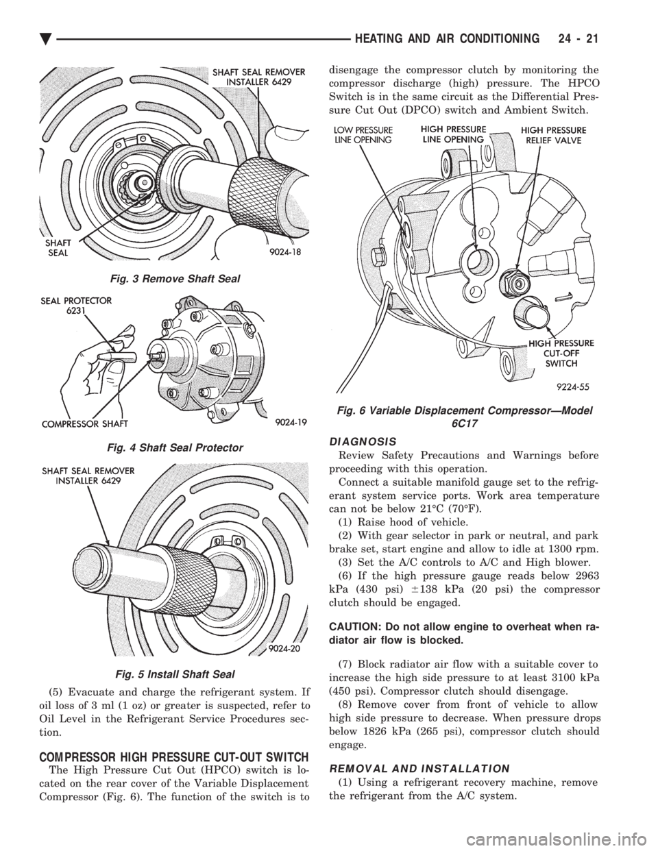
(5) Evacuate and charge the refrigerant system. If
oil loss of 3 ml (1 oz) or greater is suspected, refer to
Oil Level in the Refrigerant Service Procedures sec-
tion.
COMPRESSOR HIGH PRESSURE CUT-OUT SWITCH
The High Pressure Cut Out (HPCO) switch is lo-
cated on the rear cover of the Variable Displacement
Compressor (Fig. 6). The function of the switch is to disengage the compressor clutch by monitoring the
compressor discharge (high) pressure. The HPCO
Switch is in the same circuit as the Differential Pres-
sure Cut Out (DPCO) switch and Ambient Switch.
DIAGNOSIS
Review Safety Precautions and Warnings before
proceeding with this operation. Connect a suitable manifold gauge set to the refrig-
erant system service ports. Work area temperature
can not be below 21ÉC (70ÉF). (1) Raise hood of vehicle.
(2) With gear selector in park or neutral, and park
brake set, start engine and allow to idle at 1300 rpm. (3) Set the A/C controls to A/C and High blower.
(6) If the high pressure gauge reads below 2963
kPa (430 psi) 6138 kPa (20 psi) the compressor
clutch should be engaged.
CAUTION: Do not allow engine to overheat when ra-
diator air flow is blocked.
(7) Block radiator air flow with a suitable cover to
increase the high side pressure to at least 3100 kPa
(450 psi). Compressor clutch should disengage. (8) Remove cover from front of vehicle to allow
high side pressure to decrease. When pressure drops
below 1826 kPa (265 psi), compressor clutch should
engage.
REMOVAL AND INSTALLATION
(1) Using a refrigerant recovery machine, remove
the refrigerant from the A/C system.
Fig. 3 Remove Shaft Seal
Fig. 4 Shaft Seal Protector
Fig. 5 Install Shaft Seal
Fig. 6 Variable Displacement CompressorÐModel 6C17
Ä HEATING AND AIR CONDITIONING 24 - 21
Page 2328 of 2438
FIXED DISPLACEMENT COMPRESSORÐMODEL 10PA17 INDEX
page page
Compressor ............................. 24
Compressor Clutch/Coil Assembly ............ 24
Compressor Front Shaft Seal ............... 27 Compressor High-Pressure Relief Valve
....... 30
Refrigerant System Diagnosis ............... 30
COMPRESSOR
COMPRESSOR NOISE
Excessive noise that occurs when the air condition-
ing is being used, can be caused by:
² Loose bolts
² Mounting brackets
² Loose clutch
² Excessive high refrigerant system operating pres-
sure Verify compressor drive belt condition, proper re-
frigerant charge and head pressure before compressor
repair is performed. For noise diagnostic procedures, refer to the Com-
pressor Noise and Compressor Clutch Diagnosis
chart in this section.
REMOVAL AND INSTALLATION
The A/C compressor may be removed and posi-
tioned without discharging the refrigerant system.
Discharging is not necessary if removing the A/C
compressor clutch/coil assembly, engine, cylinder
head, or generator.
WARNING: REFRIGERANT PRESSURES REMAIN
HIGH EVEN THOUGH THE ENGINE MAY BE
TURNED OFF. BEFORE REMOVING A FULLY
CHARGED COMPRESSOR, REVIEW THE SAFETY
PRECAUTIONS AND WARNINGS SECTION IN THIS
GROUP. DO NOT TWIST OR KINK THE REFRIGER-
ANT LINES WHEN REMOVING A FULLY CHARGED
COMPRESSOR. SAFETY GLASSES MUST BE
WORN.
(1) Disconnect Negative battery cable.
(2) Loosen and remove drive belts (refer to Group
7, Cooling System) and disconnect compressor clutch
wire lead. (3) Remove refrigerant lines from compressor (if
necessary). (4) Remove compressor attaching nuts and bolts.
(5) Remove compressor. If refrigerant lines were
not removed, lift compressor/clutch assembly and tie
it to a suitable component. To install, reverse the preceding operation. If nec-
essary, refer to Charging Refrigerant System in the
Refrigerant Service Procedures section.
COMPRESSOR CLUTCH/COIL ASSEMBLY
CLUTCH INOPERATIVE
The air conditioning compressor clutch electrical
circuit is controlled by the engine controller. The
controller is located in the engine compartment out-
board of the battery. If the compressor clutch does not engage:
Verify refrigerant charge.
If the compressor clutch still does not engage check
for battery voltage at the low pressure or differential
pressure cut-off switch located on the expansion
valve. If voltage is not detected, refer to:
² Group 8W, Wiring Diagrams.
² The appropriate Powertrain Diagnostic Procedures
Manual for diagnostic information. If voltage is detected at the cut-off switch, recon-
nect switch. Then check for battery voltage between
the compressor clutch connector terminals. If voltage is detected, perform A/C Clutch Coil
Tests.
CLUTCH COIL TESTS
(1) Verify battery state of charge. (Test indicator
in battery should be green). (2) Connect an ammeter (0-10 ampere scale) in se-
ries with the clutch coil terminal. Use a volt meter
(0-20 volt scale) with clip leads measuring voltage
across the battery and A/C clutch. (3) With A/C control in A/C mode and blower at
low speed, start the engine and run at normal idle. (4) The A/C clutch should engage immediately and
the clutch voltage should be within two volts of the
battery voltage. If the A/C clutch does not engage,
test the fusible link. (5) The A/C clutch coil is acceptable if the current
draw is 2.0 to 3.7 amperes at 11.5-12.5 volts at clutch
coil. This is with the work area temperature at 21ÉC
(70ÉF). If voltage is more than 12.5 volts, add electri-
cal loads by turning on electrical accessories until
voltage reads below 12.5 volts. If coil current reads zero, the coil is open and
should be replaced. If the ammeter reading is 4 am-
peres or more, the coil is shorted and should be re-
placed. If the coil voltage is not within two volts of
the battery voltage, test clutch coil feed circuit for
excessive voltage drop.
24 - 24 HEATING AND AIR CONDITIONING Ä
Page 2336 of 2438
FIXED DISPLACEMENT COMPRESSORÐMODEL TR105 INDEX
page page
Compressor ............................. 32
Compressor Clutch/Coil Assembly ............ 32
Compressor Shaft Bearing/Seal .............. 35 Refrigerant System Diagnosis
............... 36
Thermal Limiter Switch .................... 34
COMPRESSOR
Cleanliness is extremely important when disassem-
bly of the compressor is necessary. The surfaces
around the suction and discharge ports of the com-
pressor should be cleaned thoroughly before opening
the system at these points. If compressor is removed
from vehicle, apply tape to the opened ports to pre-
vent any contamination.
REMOVAL
(1) Disconnect battery negative cable.
(2) Loosen and remove drive belts (refer to Group
7, Cooling System). (3) Disconnect compressor clutch wire lead.
(4) Using a refrigerant recovery machine, remove
refrigerant from the A/C system. (5) Remove refrigerant lines from compressor.
(6) Remove compressor attaching bolts.
(7) Remove compressor.
INSTALLATION
(1) Position the compressor on the mount and fit
drive belt. (2) Tighten the compressor attaching bolts to 41
N Im (30 ft. lbs.) torque.
(3) Adjust drive belt (see Group 7, Cooling Sys-
tem). (4) Install refrigerant hoses.
(5) Connect the clutch wire.
(6) Evacuate and charge the system.
(7) Connect the battery negative cable.
COMPRESSOR CLUTCH/COIL ASSEMBLY
CLUTCH INOPERATIVE
The air conditioning compressor clutch electrical
circuit is controlled by the engine controller. The
controller is located in the engine compartment out-
board of the battery. If the compressor clutch does not engage:
Verify refrigerant charge.
If the compressor clutch still does not engage check
for battery voltage at the low pressure or differential
pressure cut-off switch located on the expansion
valve. If voltage is not detected, refer to:
² Group 8W, Wiring Diagrams.
² The appropriate Powertrain Diagnostic Procedures
Manual for diagnostic information. If voltage is detected at the cut-off switch, recon-
nect switch. Then check for battery voltage between
the compressor clutch connector terminals. If voltage is detected, perform A/C Clutch Coil
Tests.
CLUTCH COIL TESTS
(1) Verify battery state of charge. (Test indicator
in battery should be green). (2) Connect an ammeter (0-10 ampere scale) in se-
ries with the clutch coil terminal. Use a volt meter
(0-20 volt scale) with clip leads measuring voltage
across the battery and A/C clutch. (3) With A/C control in A/C mode and blower at
low speed, start the engine and run at normal idle. (4) The A/C clutch should engage immediately and
the clutch voltage should be within two volts of the
battery voltage. If the A/C clutch does not engage,
test the fusible link. (5) The A/C clutch coil is acceptable if the current
draw is 2.0 to 3.7 amperes at 11.5-12.5 volts at clutch
coil. This is with the work area temperature at 21ÉC
(70ÉF). If voltage is more than 12.5 volts, add electri-
cal loads by turning on electrical accessories until
voltage reads below 12.5 volts. If coil current reads zero, the coil is open and
should be replaced. If the ammeter reading is 4 am-
peres or more, the coil is shorted and should be re-
placed. If the coil voltage is not within two volts of
the battery voltage, test clutch coil feed circuit for
excessive voltage drop.
REMOVAL
(1) Remove the compressor from the mount.
(2) To prevent compressor shaft rotation, install 2
(6 mm) bolts, along with 2 wrenches, to the threaded
holes in the armature plate (Fig. 1). Remove com-
pressor shaft nut. (3) Tap the armature plate with a plastic and re-
move plate and shim(s).
CAUTION: Do not use screwdrivers between the ar-
mature plate assembly and rotor-pulley to remove
the armature plate. This may damage the armature
plate assembly.
24 - 32 HEATING AND AIR CONDITIONING Ä
Page 2351 of 2438
COMPONENT SERVICE PROCEDURES INDEX
page page
Air Distribution Duct ...................... 50
Air Distribution Duct ...................... 52
Ambient Switch .......................... 47
Blend-Air Door .......................... 64
Blower Motor ............................ 58
Blower Motor Wheel Assembly .............. 58
Blower Resistor Block ..................... 49
Condensate Drain Tube ................... 64
Condenser Assembly ...................... 57
Condenser Fan Control Switch .............. 47
Defroster Duct ........................... 51
Defroster Duct Adapter .................... 51
Defroster Ducts/Demister Ducts and Hoses ..... 52
Differential Pressure Cut-Out Switch Diagnosis . . 48
Evaporator Coil .......................... 64 Expansion Valve
......................... 55
Filter-Drier Assembly ...................... 57
Fin-Sensing Cycling Clutch Switch ............ 53
Heater Core ............................ 64
Heater Hoses ........................... 51
Heater-A/C Unit AssemblyÐRemoval and Installation ............................ 61
Heater-A/C Unit Recondition ................ 63
Low or Differential Pressure Cut-Off Switch ..... 54
Temperature Control CableÐAA,AP,AG and AJ Models ............................ 49
Temperature Control CableÐAC/AY Models .... 48
Vacuum ActuatorÐFresh/Recirc Door ......... 50
Vacuum ActuatorsÐMode Doors ............. 52
AMBIENT SWITCH
The ambient switch is a temperature sensor located
in front of the condenser behind the grille (Fig. 1).
The ambient switch prevents the compressor from
engaging in cold temperatures. The ambient switch
is a sealed factory calibrated unit. It must be re-
placed if defective.
AMBIENT SWITCH TEST
(1) Disconnect ambient switch wire connector.
(2) Using a suitable ohm meter or continuity
tester, test for continuity across the ambient switch
terminals. (a) At temperature above 10ÉC (50ÉF), the switch
circuit should be complete. (b) Chill the switch with ice to below 10ÉC (50ÉF)
and test for continuity. The switch circuit should
be open, with continuity not detected.
Replace ambient switch if defective.
REMOVAL AND INSTALLATION
(1) Remove the one attaching screw.
(2) Remove the sensor/bracket assembly from the
vehicle. To install, reverse the preceding operation.
CONDENSER FAN CONTROL SWITCH
The Fan Control Switch is located on the plumbing
discharge line at the A/C compressor (Fig. 2). The fan
control switch cycles the radiator/condenser fan on and
off by monitoring the compressor discharge pressure.
The radiator top tank temperature sensor can over ride
the function of the fan control switch. It can cycle the
radiator/condenser fan on and off depending on the
engine temperature.
FAN CONTROL SWITCH DIAGNOSIS
Review Safety Precautions and Warnings before pro-
ceeding. Connect a manifold gauge set to the refriger-
ant system service ports. Work area temperature can
not be below 21ÉC (70ÉF).
Fig. 1 Ambient Temperature Sensor SwitchÐTypical Mounting
Fig. 2 Condenser Fan Control Switch
Ä HEATING AND AIR CONDITIONING 24 - 47
Page 2352 of 2438
WARNING: AVOID RADIATOR/CONDENSER FAN
BLADES WHEN WORKING IN THE RADIATOR
AREA. FAN IS CONTROLLED BY TEMPERATURE
AND CAN START ANY TIME IGNITION IS ON. PER-
SONAL INJURY CAN RESULT.
(1) Disconnect fan control switch wire connector.
(2) Using a suitable jumper wire, jump across ter-
minals in wire connector. (3) Connect a suitable continuity tester across fan
control switch terminals. (4) Start engine and set idle at 1300 rpm. The ra-
diator fan should run constantly. (5) Set the A/C controls to A/C and high blower.
(6) If the high pressure gauge reads below 1102
kPa (160 psi) there should be no continuity across
the switch terminals.
CAUTION: Do not allow engine to overheat when ra-
diator air flow is blocked.
(7) Block radiator air flow with a suitable cover to
increase the high side pressure to at least 1585 kPa
(230 psi). Electrical continuity should be detected
across the fan control switch terminals. (8) Remove cover from front of vehicle to allow
high side pressure to decrease. When pressure drops
below 1102 kPa (160 psi), continuity should cease. If fan control switch is defective, replace it.
REMOVAL AND INSTALLATION
CAUTION: Refrigerant removal is not necessary
when removing the Condenser Fan Control Switch.
However, a small amount of refrigerant will vent
from the switch port. Review the refrigerant han-
dling section of Safety Precautions and Warnings in
the General Information section of this Group.
(1) Disconnect wire connector from condenser fan
control switch. (2) Loosen and quickly rotate the switch counter-
clockwise and separate from the high pressure line
switch port. To install, reverse the preceding operation.
DIFFERENTIAL PRESSURE CUT-OUT SWITCH
DIAGNOSIS
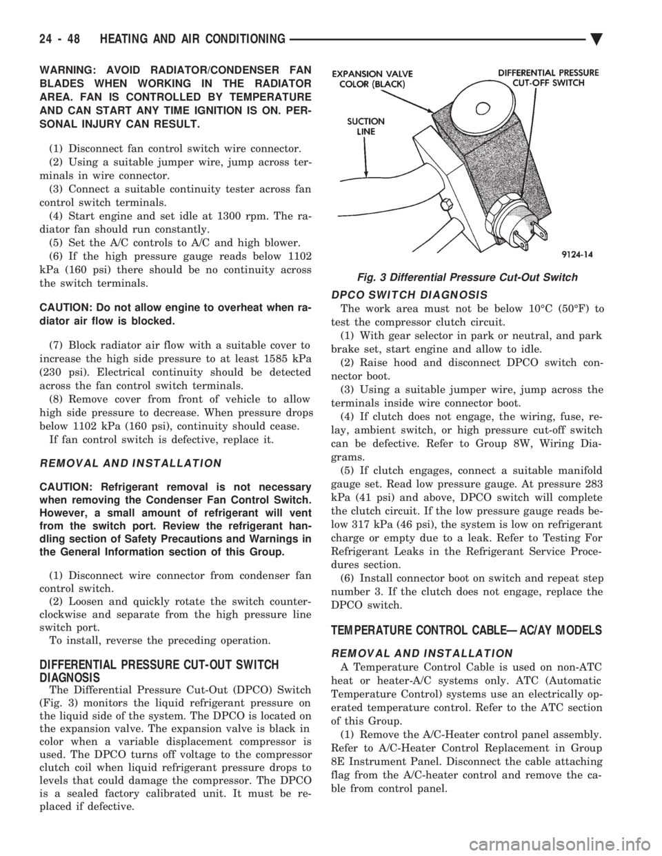
The Differential Pressure Cut-Out (DPCO) Switch
(Fig. 3) monitors the liquid refrigerant pressure on
the liquid side of the system. The DPCO is located on
the expansion valve. The expansion valve is black in
color when a variable displacement compressor is
used. The DPCO turns off voltage to the compressor
clutch coil when liquid refrigerant pressure drops to
levels that could damage the compressor. The DPCO
is a sealed factory calibrated unit. It must be re-
placed if defective.
DPCO SWITCH DIAGNOSIS
The work area must not be below 10ÉC (50ÉF) to
test the compressor clutch circuit. (1) With gear selector in park or neutral, and park
brake set, start engine and allow to idle. (2) Raise hood and disconnect DPCO switch con-
nector boot. (3) Using a suitable jumper wire, jump across the
terminals inside wire connector boot. (4) If clutch does not engage, the wiring, fuse, re-
lay, ambient switch, or high pressure cut-off switch
can be defective. Refer to Group 8W, Wiring Dia-
grams. (5) If clutch engages, connect a suitable manifold
gauge set. Read low pressure gauge. At pressure 283
kPa (41 psi) and above, DPCO switch will complete
the clutch circuit. If the low pressure gauge reads be-
low 317 kPa (46 psi), the system is low on refrigerant
charge or empty due to a leak. Refer to Testing For
Refrigerant Leaks in the Refrigerant Service Proce-
dures section. (6) Install connector boot on switch and repeat step
number 3. If the clutch does not engage, replace the
DPCO switch.
TEMPERATURE CONTROL CABLEÐAC/AY MODELS
REMOVAL AND INSTALLATION
A Temperature Control Cable is used on non-ATC
heat or heater-A/C systems only. ATC (Automatic
Temperature Control) systems use an electrically op-
erated temperature control. Refer to the ATC section
of this Group. (1) Remove the A/C-Heater control panel assembly.
Refer to A/C-Heater Control Replacement in Group
8E Instrument Panel. Disconnect the cable attaching
flag from the A/C-heater control and remove the ca-
ble from control panel.
Fig. 3 Differential Pressure Cut-Out Switch
24 - 48 HEATING AND AIR CONDITIONING Ä
Page 2358 of 2438
housing) through the hole in the housing. Feed the
wire harness and connector through the opening and
into the housing (Fig. 19). (3) Work through the air inlet opening (to the left of
the blower motor wheel). Pull the fin-sensing cycling
switch from the A/C evaporator (Fig. 20). The metal
probe on the switch is pushed into the evapora-
tor approximately three inches.
To install, reverse the preceding operation. The
switch probe should not be installed in the original
location (hole). Insert the probe in the evaporator coil
approximately 5 mm (3 to 4 fins) to the right or left of
the position it was removed. This will insure correct
temperature sensing and system performance. Exces-
sive force should not be required for probe insertion.
Care should be taken not to damage the A/C evaporator
coil or the switch probe.
LOW OR DIFFERENTIAL PRESSURE CUT-OFF
SWITCH
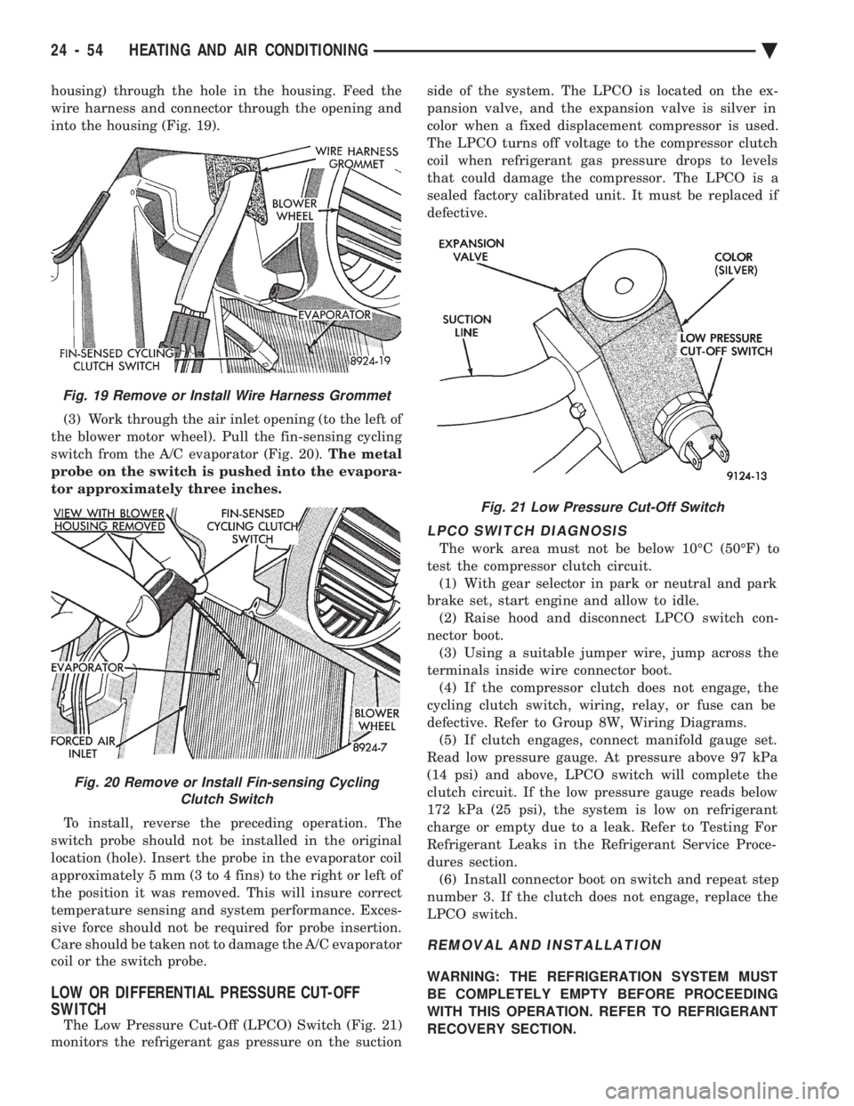
The Low Pressure Cut-Off (LPCO) Switch (Fig. 21)
monitors the refrigerant gas pressure on the suction side of the system. The LPCO is located on the ex-
pansion valve, and the expansion valve is silver in
color when a fixed displacement compressor is used.
The LPCO turns off voltage to the compressor clutch
coil when refrigerant gas pressure drops to levels
that could damage the compressor. The LPCO is a
sealed factory calibrated unit. It must be replaced if
defective.
LPCO SWITCH DIAGNOSIS
The work area must not be below 10ÉC (50ÉF) to
test the compressor clutch circuit. (1) With gear selector in park or neutral and park
brake set, start engine and allow to idle. (2) Raise hood and disconnect LPCO switch con-
nector boot. (3) Using a suitable jumper wire, jump across the
terminals inside wire connector boot. (4) If the compressor clutch does not engage, the
cycling clutch switch, wiring, relay, or fuse can be
defective. Refer to Group 8W, Wiring Diagrams. (5) If clutch engages, connect manifold gauge set.
Read low pressure gauge. At pressure above 97 kPa
(14 psi) and above, LPCO switch will complete the
clutch circuit. If the low pressure gauge reads below
172 kPa (25 psi), the system is low on refrigerant
charge or empty due to a leak. Refer to Testing For
Refrigerant Leaks in the Refrigerant Service Proce-
dures section. (6) Install connector boot on switch and repeat step
number 3. If the clutch does not engage, replace the
LPCO switch.
REMOVAL AND INSTALLATION
WARNING: THE REFRIGERATION SYSTEM MUST
BE COMPLETELY EMPTY BEFORE PROCEEDING
WITH THIS OPERATION. REFER TO REFRIGERANT
RECOVERY SECTION.
Fig. 21 Low Pressure Cut-Off Switch
Fig. 19 Remove or Install Wire Harness Grommet
Fig. 20 Remove or Install Fin-sensing Cycling Clutch Switch
24 - 54 HEATING AND AIR CONDITIONING Ä
Page 2361 of 2438
INSTALLATION
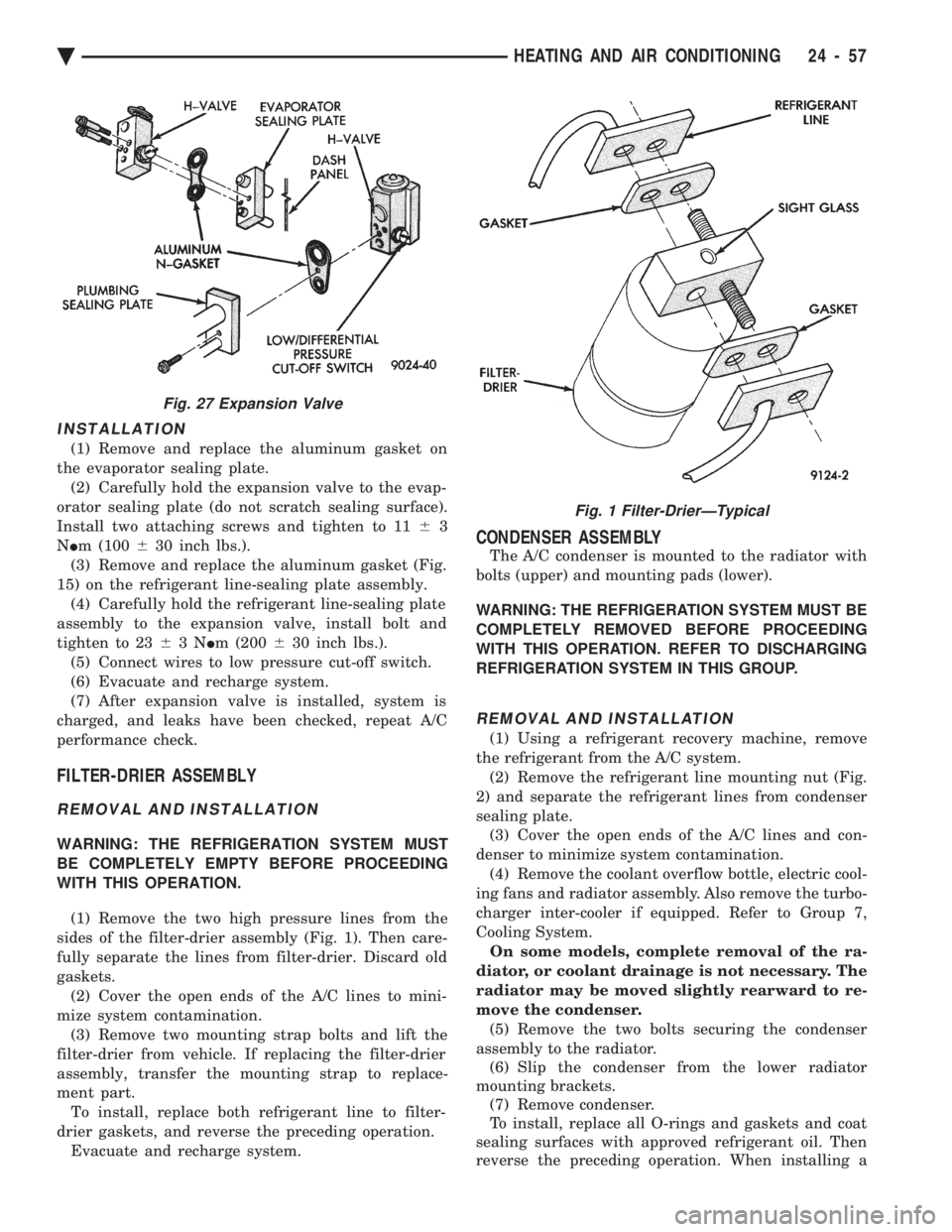
(1) Remove and replace the aluminum gasket on
the evaporator sealing plate. (2) Carefully hold the expansion valve to the evap-
orator sealing plate (do not scratch sealing surface).
Install two attaching screws and tighten to 11 63
N Im (100 630 inch lbs.).
(3) Remove and replace the aluminum gasket (Fig.
15) on the refrigerant line-sealing plate assembly. (4) Carefully hold the refrigerant line-sealing plate
assembly to the expansion valve, install bolt and
tighten to 23 63N Im (200 630 inch lbs.).
(5) Connect wires to low pressure cut-off switch.
(6) Evacuate and recharge system.
(7) After expansion valve is installed, system is
charged, and leaks have been checked, repeat A/C
performance check.
FILTER-DRIER ASSEMBLY
REMOVAL AND INSTALLATION
WARNING: THE REFRIGERATION SYSTEM MUST
BE COMPLETELY EMPTY BEFORE PROCEEDING
WITH THIS OPERATION.
(1) Remove the two high pressure lines from the
sides of the filter-drier assembly (Fig. 1). Then care-
fully separate the lines from filter-drier. Discard old
gaskets. (2) Cover the open ends of the A/C lines to mini-
mize system contamination. (3) Remove two mounting strap bolts and lift the
filter-drier from vehicle. If replacing the filter-drier
assembly, transfer the mounting strap to replace-
ment part. To install, replace both refrigerant line to filter-
drier gaskets, and reverse the preceding operation. Evacuate and recharge system.
CONDENSER ASSEMBLY
The A/C condenser is mounted to the radiator with
bolts (upper) and mounting pads (lower).
WARNING: THE REFRIGERATION SYSTEM MUST BE
COMPLETELY REMOVED BEFORE PROCEEDING
WITH THIS OPERATION. REFER TO DISCHARGING
REFRIGERATION SYSTEM IN THIS GROUP.
REMOVAL AND INSTALLATION
(1) Using a refrigerant recovery machine, remove
the refrigerant from the A/C system. (2) Remove the refrigerant line mounting nut (Fig.
2) and separate the refrigerant lines from condenser
sealing plate. (3) Cover the open ends of the A/C lines and con-
denser to minimize system contamination. (4) Remove the coolant overflow bottle, electric cool-
ing fans and radiator assembly. Also remove the turbo-
charger inter-cooler if equipped. Refer to Group 7,
Cooling System. On some models, complete removal of the ra-
diator, or coolant drainage is not necessary. The
radiator may be moved slightly rearward to re-
move the condenser. (5) Remove the two bolts securing the condenser
assembly to the radiator. (6) Slip the condenser from the lower radiator
mounting brackets. (7) Remove condenser.
To install, replace all O-rings and gaskets and coat
sealing surfaces with approved refrigerant oil. Then
reverse the preceding operation. When installing a
Fig. 27 Expansion Valve
Fig. 1 Filter-DrierÐTypical
Ä HEATING AND AIR CONDITIONING 24 - 57