1993 CHEVROLET PLYMOUTH ACCLAIM low oil pressure
[x] Cancel search: low oil pressurePage 1919 of 2438
STEERING
CONTENTS
page page
ACUSTAR STANDARD AND TILT STEERING COLUMN ............................ 28
AUTOMATIC TRANSMISSION SHIFTER/IGNITION INTERLOCK .......................... 36
GENERAL INFORMATION .................. 1 POWER STEERING GEAR
................ 25
POWER STEERING PUMPS ................ 1
SPECIFICATIONS AND TIGHTENING REFERENCE .......................... 42
GENERAL INFORMATION
Safety goggles should be worn at all times
when working on any steering gear or pump. Throughout this group, references may be made to
a particular vehicle by letter or number designation.
A chart showing the breakdown of these designations
is included in the Introduction Section at the front of
this service manual. The power steering system consists of these four
major components. Power Steering Pump, Power
Steering Gear, Pressure Hose, and Return Line.
Turning of the steering wheel is converted into lin-
ear travel through the meshing of the helical pinion teeth with the rack teeth. Power assist steering is
provided by an open center, rotary type control valve.
It is used to direct oil from the power steering pump
to either side of the integral steering rack piston. Road feel is controlled by the diameter of a torsion
bar which initially steers the vehicle. As steering ef-
fort increases as in a turn, the torsion bar twists,
causing relative rotary motion between the rotary
valve body and valve spool. This movement directs
oil behind the integral rack piston, which in turn,
builds up hydraulic pressure and assists in the turn-
ing effort.
POWER STEERING PUMPS
INDEX
page page
Checking Power Steering Fluid Level .......... 9
Flow Control Valve Fitting O-Ring Seal ........ 23
General Information ........................ 1
Power Steering Hoses ..................... 11
Power Steering Pressure Switch ............. 10
Power Steering Pump Fluid Reservoirs ........ 22 Power Steering Pump Pressure Test
........... 9
Power Steering Pump Pulley Service .......... 20
Power Steering Pump Removal .............. 12
Power Steering Pump Service ................ 2
Power Steering PumpÐInitial Operation ....... 24
Steering Components Service Diagnosis ........ 2
GENERAL INFORMATION
Hydraulic pressure for operation of the power
steering gear is provided by a belt driven power
steering pump. The power steering pump is a con-
stant flow rate and displacement, vane type pump.
Different styles of Saginaw power steering pumps are
used depending on the engine application of the ve-
hicle. On all four cylinder and 3.0-liter V-6 applications
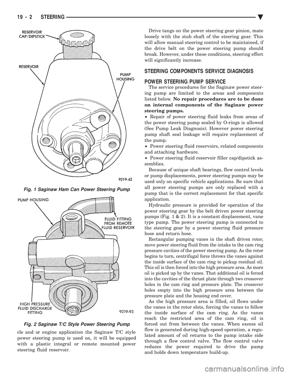
the Saginaw Ham Can power steering pump is used
(Fig. 1). On the 3.3 & 3.8-liter V-6 and Turbo III applica-
tions, different versions of the Saginaw T/C style
power steering pump is used (Fig. 2). The 3.3 & 3.8 liter V-6 engine application uses the T/C style power
steering pump with a remote mounted reservoir for
the power steering fluid. On the Turbo III application
of the T/C style power steering pump, the power
steering fluid reservoir is integral to the power steer-
ing pump. On the integral reservoir type pump (Fig. 1) the
pump housing and internal components are combined
with the reservoir to form a one-piece mechanism. The Saginaw T/C style power steering pump (Fig.
2), consists of the power steering pump internal com-
ponents and pump housing. The Saginaw T/C style
power steering pump though has no internal reser-
voir for the power steering fluid. Depending on vehi-
Ä STEERING 19 - 1
Page 1920 of 2438
cle and or engine application the Saginaw T/C style
power steering pump is used on, it will be equipped
with a plastic integral or remote mounted power
steering fluid reservoir. Drive tangs on the power steering gear pinion, mate
loosely with the stub shaft of the steering gear. This
will allow manual steering control to be maintained, if
the drive belt on the power steering pump should
break. However, under these conditions, steering effort
will significantly increase.
STEERING COMPONENTS SERVICE DIAGNOSIS
POWER STEERING PUMP SERVICE
The service procedures for the Saginaw power steer-
ing pump are limited to the areas and components
listed below. No repair procedures are to be done
on internal components of the Saginaw power
steering pumps.
² Repair of power steering fluid leaks from areas of
the power steering pump sealed by O-rings is allowed
(See Pump Leak Diagnosis). However power steering
pump shaft seal leakage will require replacement of
the pump.
² Power steering fluid reservoirs, related components
and attaching hardware.
² Power steering fluid reservoir filler cap/dipstick as-
semblies. Because of unique shaft bearings, flow control levels
or pump displacements, power steering pumps may be
used only on specific vehicle applications. Be sure that
all power steering pumps are only replaced with a
pump that is the correct replacement for that specific
application. Hydraulic pressure is provided for operation of the
power steering gear by the belt driven power steering
pumps (Fig . 1 & 2). It is a constant displacement, vane
type pump. The power steering pump is connected to
the steering gear by a power steering fluid pressure
hose and return hose.
Rectangular pumping vanes in the shaft driven rotor,
move power steering fluid from the intake to the cam ring
pressure cavities of the power steering pump. As the rotor
begins to turn, centrifugal force throws the vanes against
the inside surface of the cam ring to pickup residual oil.
This oil is then forced into the high pressure area. As more
oil is picked up by the vanes. That additional oil is forced
into the cavities of the thrust plate through two crossover
holes in the cam ring and pressure plate. The crossover
holes empty into the high pressure area between the
pressure plate and the housing end cover.
As the high pressure area is filled, oil flows under
the vanes in the rotor slots, forcing the vanes to follow
the inside surface of the cam ring. As the vanes
reach the restricted area of the cam ring, oil is
forced out from between the vanes. When excess oil
flow is generated during high-speed operation, a regu-
lated amount of oil returns to the pump intake side
through a flow control valve. The flow control valve
reduces the power required to drive the pump
and holds down temperature build-up.
Fig. 1 Saginaw Ham Can Power Steering Pump
Fig. 2 Saginaw T/C Style Power Steering Pump
19 - 2 STEERING Ä
Page 1927 of 2438
When steering conditions exceed maximum pres-
sure requirements, such as when the wheels are
turned against the stops. The pressure built up in
the steering gear exerts pressure on the spring end of
the flow control valve. The high pressure lifts the re-
lief valve ball from its seat and allows oil to flow
through a trigger orifice located in the outlet fitting.
This reduces pressure on the spring end of the flow
control valve which then opens and allows the oil to
return to the intake side of the pump. This action
limits maximum pressure output of the pump to a
safe level. Under normal power steering pump operating con-
ditions, pressure requirements of the pump are below
maximum, causing the pressure relief valve to re-
main closed.
CHECKING POWER STEERING FLUID LEVEL
WARNING: FLUID LEVEL SHOULD BE CHECKED
WITH ENGINE OFF TO PREVENT INJURY FROM
MOVING PARTS. DO NOT USE AUTOMATIC TRANS-
MISSION FLUID IN THE POWER STEERING SYS-
TEM. DO NOT OVERFILL THE POWER STEERING
SYSTEM.
Wipe reservoir filler cap free of dirt, before check-
ing power steering fluid level. The dipstick should in- dicate FULL COLD when fluid is at normal ambient
temperature, approximately 21ÉC to 27ÉC (70ÉF to
80ÉF). In all pumps add fluid as necessary to obtain
proper level, using only MopartPower Steering
Fluid, or equivalent. DO NOT USE ANY TYPE
OF AUTOMATIC TRANSMISSION FLUID.
POWER STEERING PUMP PRESSURE TEST
The following procedure can be used to test the op-
eration of the power steering system on the vehicle. (1) Check power steering pump drive belt tension
and adjust as necessary. (2) Disconnect power steering fluid pressure hose,
at steering gear or power steering pump. Use a con-
tainer for dripping fluid. (3) Connect Pressure Gauge, Special Tool C-3309-E
(Fig. 1) to both hoses using adapter fittings. Connect
spare pressure hose to gear or pump. (4) Completely open valve on Special Tool
C-3309-E (Fig. 1). (5) Start engine and let idle.
(6) Check power steering fluid level, and add fluid
as necessary. (7) Gauge should read below 862 kPa (125 psi), if
above, inspect the hoses for restrictions and repair as
necessary. The initial pressure should be in the
range of 345-552 kPa (50-80 psi).
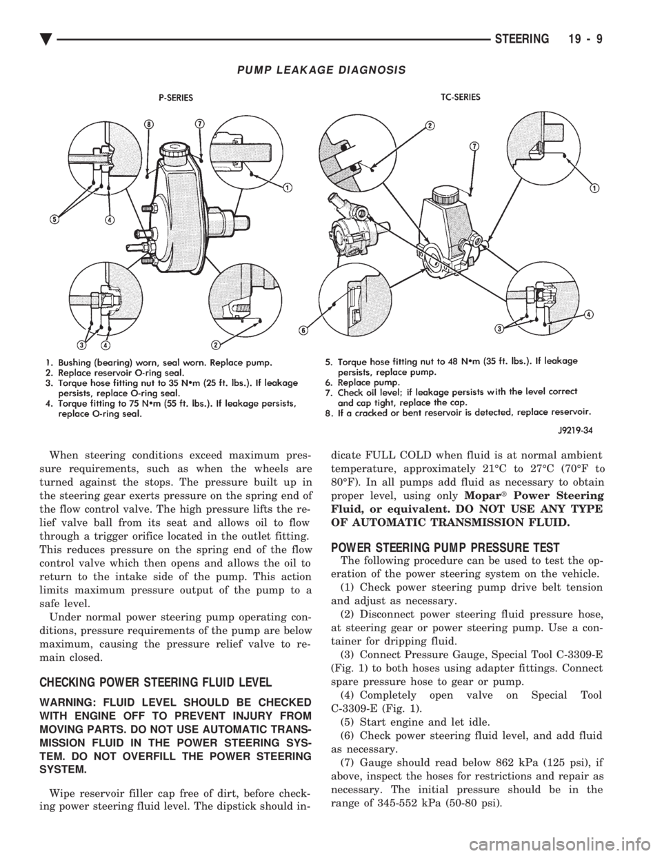
PUMP LEAKAGE DIAGNOSIS
Ä STEERING 19 - 9
Page 1929 of 2438
INSTALL
(1) Install power steering pressure switch into fit-
ting on power steering pressure hose by hand until
fully seated. Then torque power steering pressure
switch to 12 N Im (106 in. lbs.).
(2) Install vehicle wiring harness connector onto
power steering pressure switch. Be sure latch on wir-
ing harness connector is fully engaged with locking
tab on power steering pressure switch.
CAUTION: Do not use automatic transmission fluid
in power steering system. Only use Mopar T, Power
Steering Fluid, or equivalent.
(3) Fill power steering pump reservoir to correct
fluid level. (4) Connect negative cable back on negative post of
battery. (5) Start engine and turn steering wheel several
times from stop to stop to bleed air from fluid in sys-
tem. Stop engine, check fluid level, and inspect sys-
tem for leaks. See Checking Fluid Level.
POWER STEERING HOSES
Service all power steering hoses with the vehicle
raised on a hoist. Cap all open ends of hoses, power
steering pump fittings and steering gear ports to pre-
vent entry of foreign material into the components.
WARNING: POWER STEERING OIL, ENGINE PARTS
AND EXHAUST SYSTEM MAY BE EXTREMELY HOT
IF ENGINE HAS BEEN RUNNING. DO NOT START
ENGINE WITH ANY LOOSE OR DISCONNECTED
HOSES. DO NOT ALLOW HOSES TO TOUCH HOT
EXHAUST MANIFOLD OR CATALYST.
For part reference and part location on the vehicle
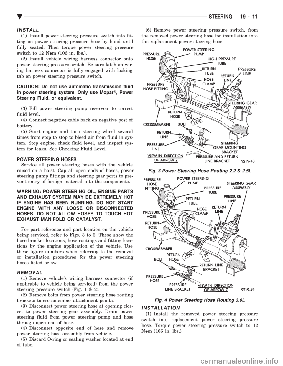
being serviced, refer to Figs. 3 to 6. These show the
hose bracket locations, hose routings and fitting loca-
tions by the engine application of the vehicle. Use
these figure numbers when referring to the removal
or installation procedures for the power steering
hoses listed below.
REMOVAL
(1) Remove vehicle's wiring harness connector (if
applicable to vehicle being serviced) from the power
steering pressure switch (Fig .1&2).
(2) Remove bolts from power steering hose routing
brackets to crossmember attachment points. (3) Disconnect power steering hose at opening clos-
est to power steering gear assembly. Drain power
steering fluid from power steering pump and hose
through open end of hose. (4) Disconnect opposite end of hose and remove
power steering hose assembly from vehicle. (5) Discard O-ring or sealing washer located at end
of tube. (6) Remove power steering pressure switch, from
the removed power steering hose for installation into
the replacement power steering hose.
INSTALLATION
(1) Install the removed power steering pressure
switch into replacement power steering pressure
hose. Torque power steering pressure switch to 12
N Im (106 in. lbs.).
Fig. 3 Power Steering Hose Routing 2.2 & 2.5L
Fig. 4 Power Steering Hose Routing 3.0L
Ä STEERING 19 - 11
Page 1930 of 2438
(2) Using a lint free towel, wipe clean open power
steering hose ends, power steering pump and steer-
ing gear ports. (3) Install new O-rings or sealing washers on the
ends of the power steering hoses. Lubricate O-rings
or sealing washers using clean power steering fluid. (4) Attach power steering hose to proper connec-
tions at power steering pump and steering gear. Cor-
rectly route power steering hoses avoiding tight
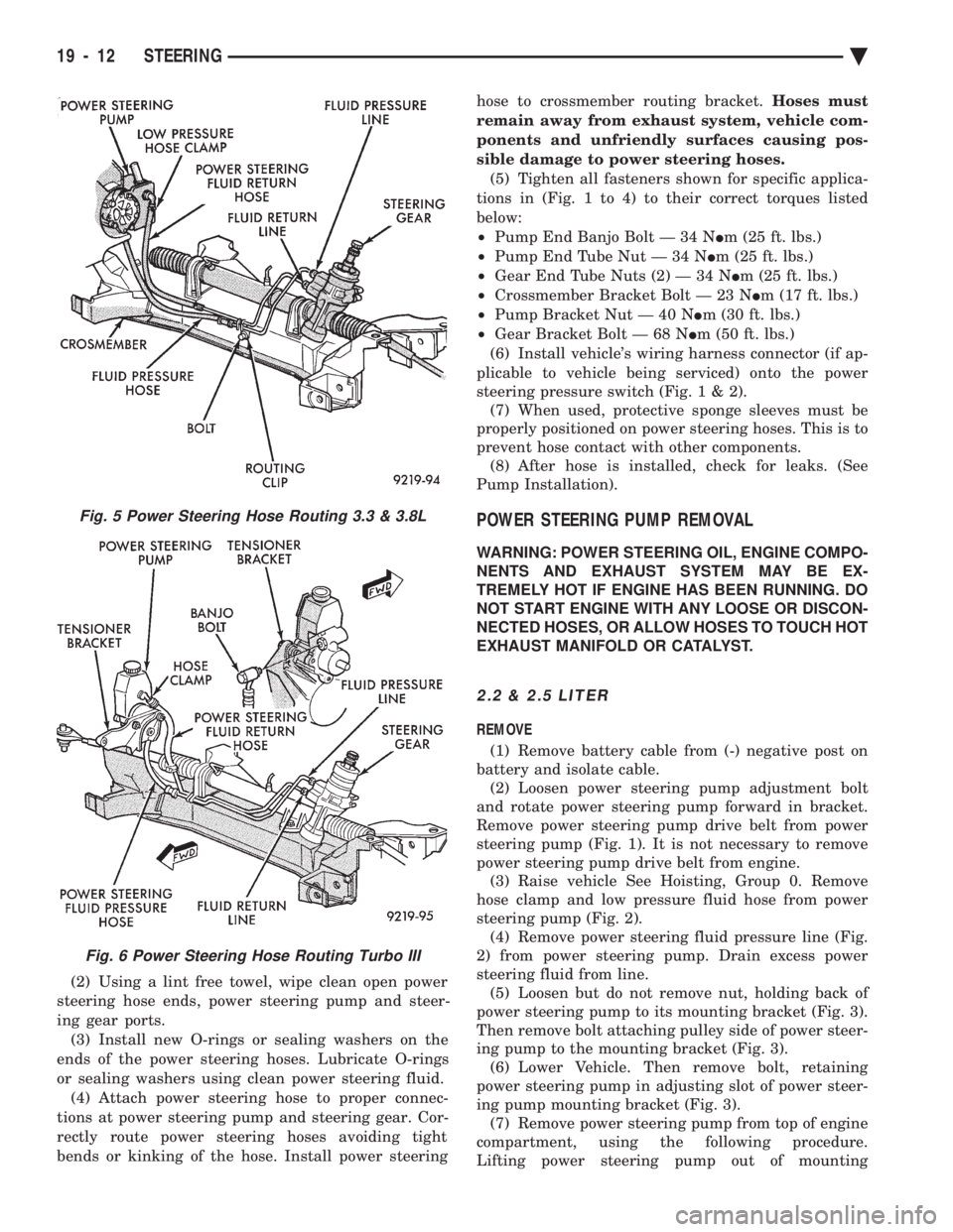
bends or kinking of the hose. Install power steering hose to crossmember routing bracket.
Hoses must
remain away from exhaust system, vehicle com-
ponents and unfriendly surfaces causing pos-
sible damage to power steering hoses. (5) Tighten all fasteners shown for specific applica-
tions in (Fig. 1 to 4) to their correct torques listed
below:
² Pump End Banjo Bolt Ð 34 N Im (25 ft. lbs.)
² Pump End Tube Nut Ð 34 N Im (25 ft. lbs.)
² Gear End Tube Nuts (2) Ð 34 N Im (25 ft. lbs.)
² Crossmember Bracket Bolt Ð 23 N Im (17 ft. lbs.)
² Pump Bracket Nut Ð 40 N Im (30 ft. lbs.)
² Gear Bracket Bolt Ð 68 N Im (50 ft. lbs.)
(6) Install vehicle's wiring harness connector (if ap-
plicable to vehicle being serviced) onto the power
steering pressure switch (Fig .1&2).
(7) When used, protective sponge sleeves must be
properly positioned on power steering hoses. This is to
prevent hose contact with other components. (8) After hose is installed, check for leaks. (See
Pump Installation).
POWER STEERING PUMP REMOVAL
WARNING: POWER STEERING OIL, ENGINE COMPO-
NENTS AND EXHAUST SYSTEM MAY BE EX-
TREMELY HOT IF ENGINE HAS BEEN RUNNING. DO
NOT START ENGINE WITH ANY LOOSE OR DISCON-
NECTED HOSES, OR ALLOW HOSES TO TOUCH HOT
EXHAUST MANIFOLD OR CATALYST.
2.2 & 2.5 LITER
REMOVE
(1) Remove battery cable from (-) negative post on
battery and isolate cable. (2) Loosen power steering pump adjustment bolt
and rotate power steering pump forward in bracket.
Remove power steering pump drive belt from power
steering pump (Fig. 1). It is not necessary to remove
power steering pump drive belt from engine. (3) Raise vehicle See Hoisting, Group 0. Remove
hose clamp and low pressure fluid hose from power
steering pump (Fig. 2). (4) Remove power steering fluid pressure line (Fig.
2) from power steering pump. Drain excess power
steering fluid from line. (5) Loosen but do not remove nut, holding back of
power steering pump to its mounting bracket (Fig. 3).
Then remove bolt attaching pulley side of power steer-
ing pump to the mounting bracket (Fig. 3). (6) Lower Vehicle. Then remove bolt, retaining
power steering pump in adjusting slot of power steer-
ing pump mounting bracket (Fig. 3). (7) Remove power steering pump from top of engine
compartment, using the following procedure.
Lifting power steering pump out of mounting
Fig. 5 Power Steering Hose Routing 3.3 & 3.8L
Fig. 6 Power Steering Hose Routing Turbo III
19 - 12 STEERING Ä
Page 1932 of 2438
(10) Connect negative cable back on negative post
of battery. (11) Start engine and turn steering wheel several
times from stop to stop to bleed air from fluid in sys-
tem. Stop engine, check fluid level, and inspect sys-
tem for leaks. See Checking Fluid Level.
3.0 LITER
REMOVE
(1) REMOVE THE (-) NEGATIVE BATTERY CA-
BLE FROM THE BATTERY AND ISOLATE CA-
BLE. (2) Remove the serpentine accessory drive belt
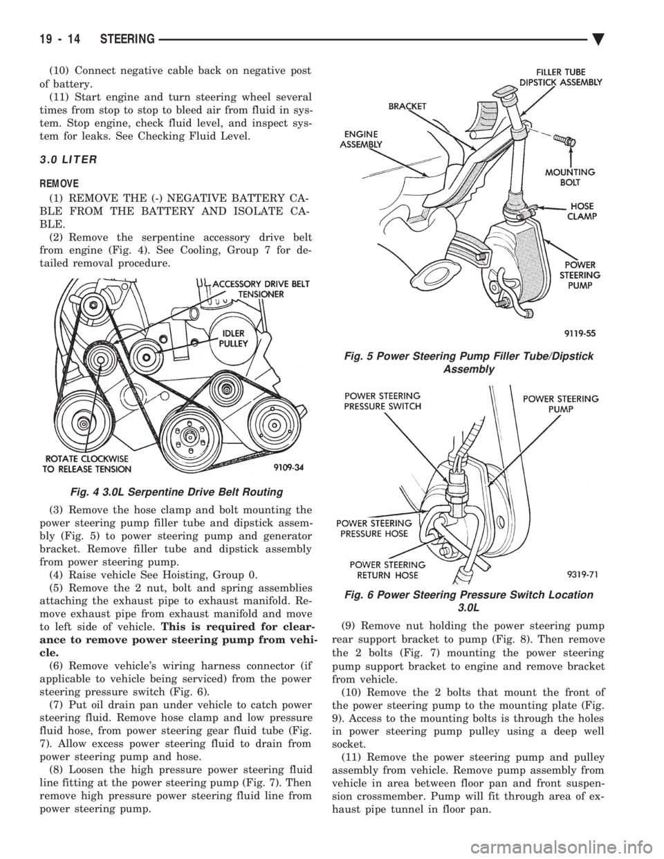
from engine (Fig. 4). See Cooling, Group 7 for de-
tailed removal procedure.
(3) Remove the hose clamp and bolt mounting the
power steering pump filler tube and dipstick assem-
bly (Fig. 5) to power steering pump and generator
bracket. Remove filler tube and dipstick assembly
from power steering pump. (4) Raise vehicle See Hoisting, Group 0.
(5) Remove the 2 nut, bolt and spring assemblies
attaching the exhaust pipe to exhaust manifold. Re-
move exhaust pipe from exhaust manifold and move
to left side of vehicle. This is required for clear-
ance to remove power steering pump from vehi-
cle. (6) Remove vehicle's wiring harness connector (if
applicable to vehicle being serviced) from the power
steering pressure switch (Fig. 6). (7) Put oil drain pan under vehicle to catch power
steering fluid. Remove hose clamp and low pressure
fluid hose, from power steering gear fluid tube (Fig.
7). Allow excess power steering fluid to drain from
power steering pump and hose. (8) Loosen the high pressure power steering fluid
line fitting at the power steering pump (Fig. 7). Then
remove high pressure power steering fluid line from
power steering pump. (9) Remove nut holding the power steering pump
rear support bracket to pump (Fig. 8). Then remove
the 2 bolts (Fig. 7) mounting the power steering
pump support bracket to engine and remove bracket
from vehicle. (10) Remove the 2 bolts that mount the front of
the power steering pump to the mounting plate (Fig.
9). Access to the mounting bolts is through the holes
in power steering pump pulley using a deep well
socket. (11) Remove the power steering pump and pulley
assembly from vehicle. Remove pump assembly from
vehicle in area between floor pan and front suspen-
sion crossmember. Pump will fit through area of ex-
haust pipe tunnel in floor pan.
Fig. 4 3.0L Serpentine Drive Belt Routing
Fig. 5 Power Steering Pump Filler Tube/Dipstick Assembly
Fig. 6 Power Steering Pressure Switch Location 3.0L
19 - 14 STEERING Ä
Page 1934 of 2438
(15) Start engine and turn steering wheel several
times from stop to stop to bleed air from fluid in sys-
tem. Stop engine, check fluid level, and inspect sys-
tem for leaks. See Checking Fluid Level.
3.3 & 3.8 LITER
REMOVE
(1) Remove the (-) negative battery cable from the
battery and isolate cable. (2) Remove the serpentine accessory drive belt
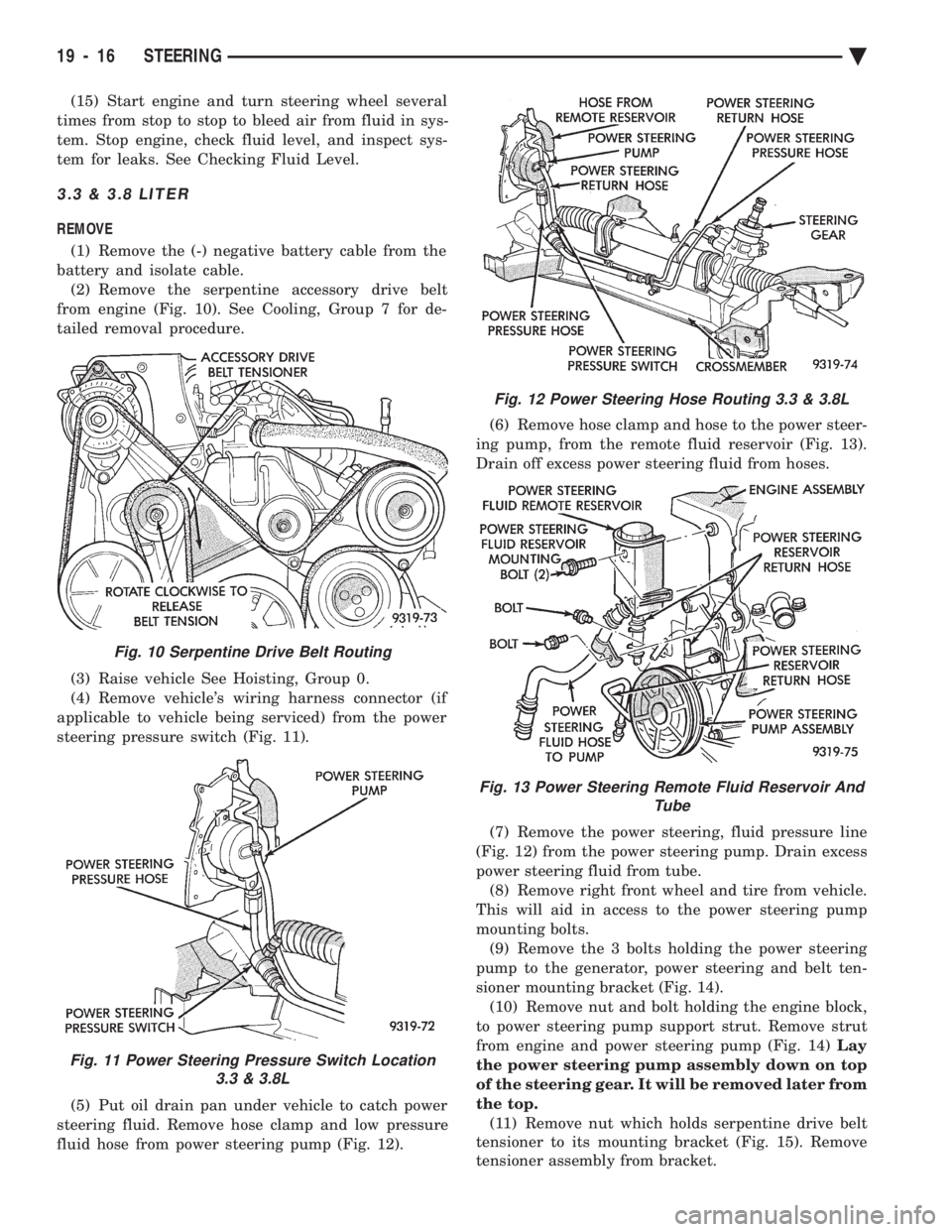
from engine (Fig. 10). See Cooling, Group 7 for de-
tailed removal procedure.
(3) Raise vehicle See Hoisting, Group 0.
(4) Remove vehicle's wiring harness connector (if
applicable to vehicle being serviced) from the power
steering pressure switch (Fig. 11).
(5) Put oil drain pan under vehicle to catch power
steering fluid. Remove hose clamp and low pressure
fluid hose from power steering pump (Fig. 12). (6) Remove hose clamp and hose to the power steer-
ing pump, from the remote fluid reservoir (Fig. 13).
Drain off excess power steering fluid from hoses.
(7) Remove the power steering, fluid pressure line
(Fig. 12) from the power steering pump. Drain excess
power steering fluid from tube. (8) Remove right front wheel and tire from vehicle.
This will aid in access to the power steering pump
mounting bolts. (9) Remove the 3 bolts holding the power steering
pump to the generator, power steering and belt ten-
sioner mounting bracket (Fig. 14). (10) Remove nut and bolt holding the engine block,
to power steering pump support strut. Remove strut
from engine and power steering pump (Fig. 14) Lay
the power steering pump assembly down on top
of the steering gear. It will be removed later from
the top. (11) Remove nut which holds serpentine drive belt
tensioner to its mounting bracket (Fig. 15). Remove
tensioner assembly from bracket.
Fig. 10 Serpentine Drive Belt Routing
Fig. 11 Power Steering Pressure Switch Location 3.3 & 3.8L
Fig. 12 Power Steering Hose Routing 3.3 & 3.8L
Fig. 13 Power Steering Remote Fluid Reservoir And Tube
19 - 16 STEERING Ä
Page 1937 of 2438
(18) Lower vehicle.
(19) Install the serpentine drive belt. Refer to (Fig.
10) for correct serpentine belt routing. See Cooling,
Group 7 for detailed installation procedure.
CAUTION: Do not use automatic transmission fluid
in power steering system. Only use Mopar T, Power
Steering Fluid, or equivalent.
(20) Fill power steering pump reservoir to correct
fluid level. (21) Connect the negative battery cable on the
negative battery post. (22) Start engine and turn steering wheel several
times from stop to stop to bleed air from fluid in sys-
tem. Stop engine, check fluid level, and inspect sys-
tem for leaks. See Checking Fluid Level.
TURBO III
REMOVE
(1) Disconnect the battery (-) negative cable from
the battery and isolate cable. (2) Raise vehicle See Hoisting, Group 0. Put oil
drain pan under vehicle to catch power steering
fluid. (3) Remove the right front underhood splash shield
for access to the serpentine belt tensioner. (4) Release the tension on the serpentine drive belt
tensioner and remove drive belt from power steering
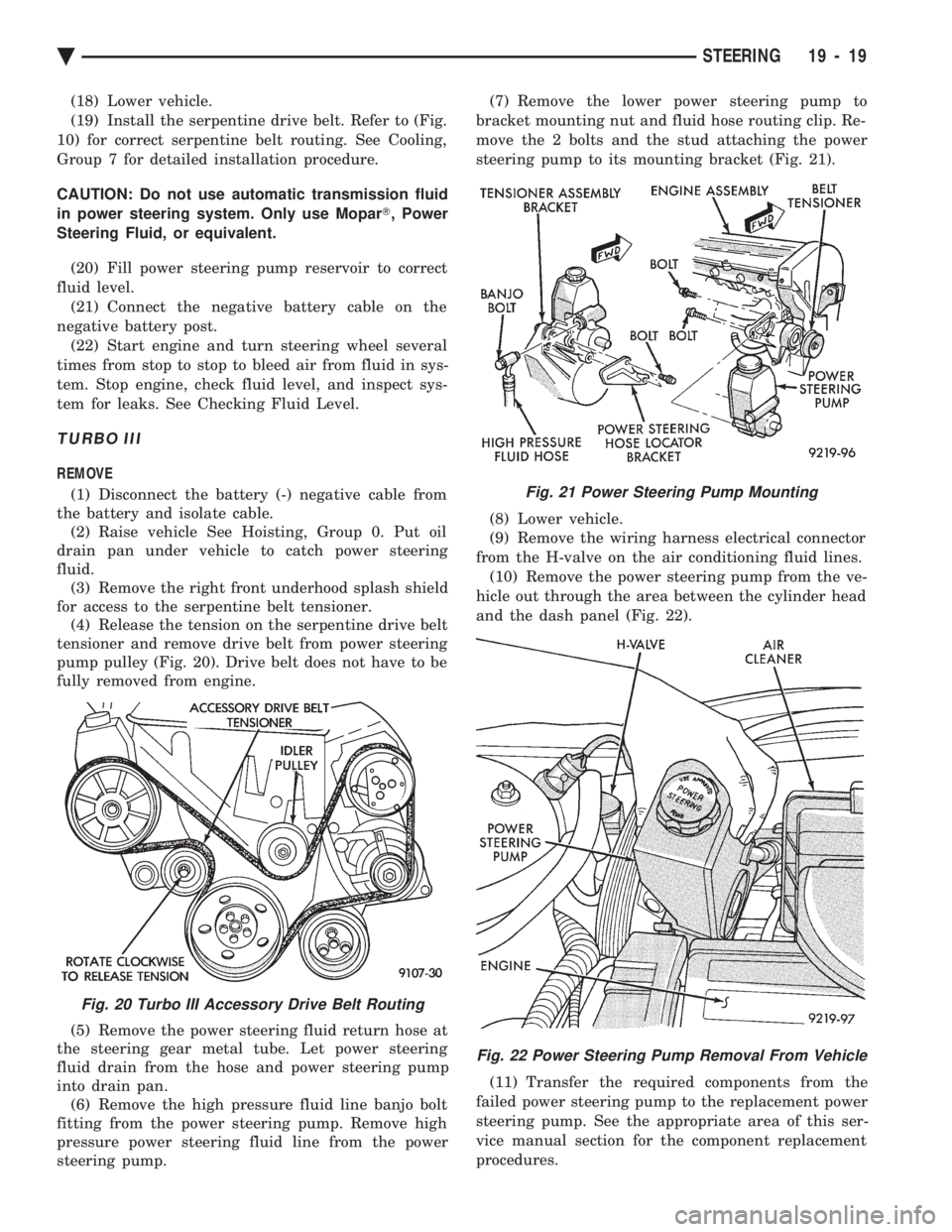
pump pulley (Fig. 20). Drive belt does not have to be
fully removed from engine.
(5) Remove the power steering fluid return hose at
the steering gear metal tube. Let power steering
fluid drain from the hose and power steering pump
into drain pan. (6) Remove the high pressure fluid line banjo bolt
fitting from the power steering pump. Remove high
pressure power steering fluid line from the power
steering pump. (7) Remove the lower power steering pump to
bracket mounting nut and fluid hose routing clip. Re-
move the 2 bolts and the stud attaching the power
steering pump to its mounting bracket (Fig. 21).
(8) Lower vehicle.
(9) Remove the wiring harness electrical connector
from the H-valve on the air conditioning fluid lines. (10) Remove the power steering pump from the ve-
hicle out through the area between the cylinder head
and the dash panel (Fig. 22).
(11) Transfer the required components from the
failed power steering pump to the replacement power
steering pump. See the appropriate area of this ser-
vice manual section for the component replacement
procedures.
Fig. 20 Turbo III Accessory Drive Belt Routing
Fig. 21 Power Steering Pump Mounting
Fig. 22 Power Steering Pump Removal From Vehicle
Ä STEERING 19 - 19